EP1090873A1 - Mobile transfer device for loading and unloading ships in harbours - Google Patents
Mobile transfer device for loading and unloading ships in harbours Download PDFInfo
- Publication number
- EP1090873A1 EP1090873A1 EP00250285A EP00250285A EP1090873A1 EP 1090873 A1 EP1090873 A1 EP 1090873A1 EP 00250285 A EP00250285 A EP 00250285A EP 00250285 A EP00250285 A EP 00250285A EP 1090873 A1 EP1090873 A1 EP 1090873A1
- Authority
- EP
- European Patent Office
- Prior art keywords
- handling device
- undercarriage
- support columns
- tower
- mobile
- Prior art date
- Legal status (The legal status is an assumption and is not a legal conclusion. Google has not performed a legal analysis and makes no representation as to the accuracy of the status listed.)
- Granted
Links
Images


Classifications
-
- B—PERFORMING OPERATIONS; TRANSPORTING
- B66—HOISTING; LIFTING; HAULING
- B66C—CRANES; LOAD-ENGAGING ELEMENTS OR DEVICES FOR CRANES, CAPSTANS, WINCHES, OR TACKLES
- B66C23/00—Cranes comprising essentially a beam, boom, or triangular structure acting as a cantilever and mounted for translatory of swinging movements in vertical or horizontal planes or a combination of such movements, e.g. jib-cranes, derricks, tower cranes
- B66C23/06—Cranes comprising essentially a beam, boom, or triangular structure acting as a cantilever and mounted for translatory of swinging movements in vertical or horizontal planes or a combination of such movements, e.g. jib-cranes, derricks, tower cranes with jibs mounted for jibbing or luffing movements
- B66C23/08—Cranes comprising essentially a beam, boom, or triangular structure acting as a cantilever and mounted for translatory of swinging movements in vertical or horizontal planes or a combination of such movements, e.g. jib-cranes, derricks, tower cranes with jibs mounted for jibbing or luffing movements and adapted to move the loads in predetermined paths
- B66C23/10—Cranes comprising essentially a beam, boom, or triangular structure acting as a cantilever and mounted for translatory of swinging movements in vertical or horizontal planes or a combination of such movements, e.g. jib-cranes, derricks, tower cranes with jibs mounted for jibbing or luffing movements and adapted to move the loads in predetermined paths the paths being substantially horizontal; Level-luffing jib-cranes
-
- B—PERFORMING OPERATIONS; TRANSPORTING
- B66—HOISTING; LIFTING; HAULING
- B66C—CRANES; LOAD-ENGAGING ELEMENTS OR DEVICES FOR CRANES, CAPSTANS, WINCHES, OR TACKLES
- B66C5/00—Base supporting structures with legs
- B66C5/02—Fixed or travelling bridges or gantries, i.e. elongated structures of inverted L or of inverted U shape or tripods
Definitions
- the invention relates to a mobile handling device for loading and unloading ships in port facilities, especially for combined container and bulk handling, using a luffing jib articulated on the tower of a harbor crane interchangeable load handling devices
- the object of the present invention is to provide a novel type which can be used in seaports Handling equipment for containers and bulk goods to create the highest level Has mobility and can be used universally.
- the tower of the harbor crane rigid with is connected to a portal-like undercarriage, which preferably has four on the Portal supports arranged steerable trolleys can be moved freely, and that for Support of the material handling equipment on the side facing the load on Undercarriage vertically extendable support beams are provided on their free ends bear vertical support columns on which can be lifted and lowered rails or Crawler tracks are arranged.
- the mobile superstructure including the superstructure and slewing gear, are no longer required the double-sided support. Instead, the tower is via a flange connection rigidly connected to the portal-like undercarriage.
- the luffing jib articulated on the tower is either powered by a cable or adjustable by a hydraulic luffing gear.
- To the rocking process in the area of Another characteristic of the boom is to dampen the boom position in a controlled manner
- Invention provided that a biased between the boom foot and tower pressure medium-operated spring storage element is provided.
- the undercarriage is preferably a Box girder designed that as the basis for the drive unit, the Lifting winches, the luffing gear and the electrical supply as well as the fuel tanks serves.
- the undercarriage can be reached via ascents or descents.
- a crane cabin in the The upper area of the tower allows the crane operator an optimal view of the Cargo and the loading area, cameras can also in the boom tip Transfer the charging situation to a monitor inside the cabin.
- the portal-like undercarriage with four arranged below the portal supports rubber-tired undercarriages enable unlimited movement in every direction Moving the device on the quay.
- the parallel movement of the material handling equipment A quay edge or water-side rail monitors a navigation system such as that of AGV vehicles is known.
- the rail trolleys of the support columns into one water-side rail into which the trolleys can be lowered.
- the handling device on the water-side rail Orientative, controlled in the longitudinal direction of the quay or ship. This will at the same time formed the support facing the water, which together with the undercarriage chassis, the support base of the material handler represents.
- the existing ones in port facilities can be used Rails on which the loading bridges usually move, the present one Handling device according to the invention only uses the water-side rail into which the Rail trolleys of the support columns are lowered.
- the undercarriage of the Transhipment device and the support columns are dimensioned such that between the extended support columns and the portal supports and below the undercarriage Clearances for travel routes are left, and the clear height between the support columns and portal supports larger than the height of container transport vehicles and - facilities.
- the space between the rail and undercarriage chassis creates space for at least two lanes, e.g. for trucks, multi-trailer systems or AGVs.
- An additional route, e.g. for trucks is between the portal supports of the undercarriage provided.
- the support beams become horizontal retracted so that the support columns are positioned near the portal supports and the center of gravity of the material handling machine is on the machine center axis. In this position, a change of location, e.g. the automatic drive from one quay to another.
- the innovative handling device can handle bulk goods According to the invention with a shorter boom and tower to a grab crane be equipped.
- the clear height of the material handling device between Support columns and portal supports is preferably for the bulk material handling provided, the clear height of the material handling device between Support columns and portal supports to be chosen so that there is a feed or Transfer hopper (hopper) finds space underneath the undercarriage
- the discharge conveyor belt conveys the bulk material leaving the hopper a quay longitudinal conveyor belt running outside of the handling device.
- the handling device proposed according to the invention is mobile and flexible in the Application.
- the cost of purchase and maintenance are compared to conventional container and bulk goods loading bridges are approx. 30-40% lower start.
- the cost advantages put the operator of the handling equipment in the Location, competitive handling costs (DM / container or DM / t bulk goods) too calculate and offer its service accordingly cheaper.
- the handling device according to the invention is when loading and unloading Containers shown in its working position.
- the drawing sketch shows that Handling device 1 in front of a container ship 3 of the new one lying on the quay 2 Generation (7000 to 8000 TEU container loading capacity).
- the material handler 1 consists essentially of the undercarriage 4 with the displaceable support 5, the tower 6 and the boom 7.
- the minimum radius of the boom 7 (which also corresponds to the transport position of the device) is shown in dash-dotted lines and marked with 7.1.
- the tower 6 and the undercarriage 4 are rigid via a flange connection 8 connected with each other.
- the two lifting winches 9.1. and 9.2 are below the tower 6 arranged.
- the load suspension device 11 attached to the lifting ropes 10.1 and 10.2 is in the example shown to accommodate ISO containers as a spreader trained and takes the load 12.
- the boom 7 is by a rope-operated luffing mechanism 13, consisting of the Luffing winch 13.1 and the block and tackle 13.2.
- a mobile one at tower 6 guided counterweight 14, which is connected by two cables 14.1 to the boom 7 compensates for part of the boom weight and thus reduces the required Drive power of the seesaw.
- a cabin 17 is on the stairs 15 or the To reach elevator 16 on the outside of tower 6.
- FIG. 2 there are four rigidly mounted portal supports on the undercarriage 4 4.1 and 4.2 provided with trolleys 18 and 19.
- the support beams 5.1 are mounted horizontally, at their free Ends of the vertical support columns 5.2 of the displaceable support 5 are arranged are.
- a rail carriage 21 on the Support cylinder 20 mounted and lowered.
- the rail undercarriage 21 is supported on a crane rail 22 laid on the water side of the quay. Longitudinally are lanes, e.g. intended for AGVs 23 and trucks 24.
- Figure 2 shows the transport position of the handling device.
- the boom is in his steepest position pivoted and the displaceable support 5 is in their Transport position retracted.
- the rail carriage 21 is by retracting the Hydraulic cylinder 20 lifted and has no contact with the rail 22.
- Der The transhipment device 1 now focuses on the device center axis.
- the Load suspension device 11 is fixed in the area of the support 5.
- the so prepared Transhipment device 1 can now on the rubber tires undercarriages 18, 19 on quay 2 be moved freely to another location.
- FIG. 4 shows the front view of the container handling device 1 on the quay 2 with the portal supports 4.1 and 4.2 rigidly attached to the undercarriage 4 and the Undercarriages 18 and 19 stands.
- the undercarriage 4 serves as the basis for the lifting winches 9.1 and 9.2, the luffing winch 13.1, the electrical room 29, the drive unit 30 and the fuel and hydraulic tank 31.
- the stairway leads parallel to tower 6 15 to cabin 16.
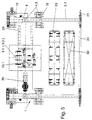
- FIG 5 is the top view of the handling device 1 below the tower shown. You can see the undercarriage 4 with the support box 4.3 and the Support bracket 5.1. The jacks 9.1 and 9.2, the luffing winch, are also shown 13.1, the bogies 18 and 19, the rail bogies 21, the E space 29 and that Drive unit 30. The support columns 5.2 are by the truss 33; connected with each other. In the free space under the undercarriage 4 between the Support columns 5.2 and the portal supports 4.1 recognize an unloaded and one with AGV 23 occupied by cargo 32.
- the permissible headroom is at Undercarriage 4 constructed so that the various devices for transporting and Sufficient space for manipulating containers and / or bulk goods.
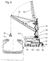
- Figure 6 is for example, a handling device according to the invention for loading and unloading Bulk goods shown.
- the handling device is designated 39.
- the device was equipped with a shorter boom 45 and a shorter tower 44.
- the most Quay 40 lying bulk cargo ship is here designated 41.
- the minimal Utilization is marked and shown with 45.1.
- a slidable conveyor belt 47 for the construction phase which below the Undercarriage 42 and between the rigidly attached portal supports 42.1 and 42.2 the bulk goods are conveyed from a hopper 48, e.g. to a Longitudinal conveyor belt 49.
- the hopper 48 is between the support columns 43.2 and Portal supports 42.1 placed. This is during the construction phase Slidable conveyor belt 47 in a position that the passage profile for the Hopper 48 not affected. After aligning the hopper with the bulk material handling device the take-off conveyor belt is in the working position shown pushed.
Abstract
Description
Die Erfindung betrifft ein mobiles Umschlaggerät zum Be- und Entladen von Schiffen in Hafenanlagen, insbesondere zum kombinierten Container- und Schüttgutumschlag, unter Einsatz eines am Turm eines Hafenkranes angelenkten Wippauslegers mit auswechselbaren LastaufnahmemittelnThe invention relates to a mobile handling device for loading and unloading ships in port facilities, especially for combined container and bulk handling, using a luffing jib articulated on the tower of a harbor crane interchangeable load handling devices
Zum Be- und Entladen von Schiffen mit bzw. von Containern oder Schüttgütern werden in Hafenanlagen vorwiegend Ladebrücken eingesetzt, die auf am Kai verlegten Schienen längs des zu be- oder entladenden Schiffes verfahrbar sind. Die Ladebrücken können nur mit großem Aufwand, z.B. mittels Umsetzvorrichtungen oder Schwimmkranen an einen anderen Standort verbracht werden, ein Aufwand der nicht nur teuer ist, sondern auch viel wertvolle Ladezeit kostet.For loading and unloading ships with or from containers or bulk goods dock levellers are mainly used in port facilities, on the quay installed rails are movable along the ship to be loaded or unloaded. The Loading bridges can only be done with great effort, e.g. by means of transfer devices or Floating cranes are moved to another location, an effort of no is only expensive, but also costs a lot of valuable loading time.
Aufgabe der vorliegenden Erfindung ist es, ein in Seehäfen einsetzbares neuartiges Umschlaggerät für Container und Schüttgüter zu schaffen, das ein Höchstmaß an Mobilität aufweist und universell verwendbar ist.The object of the present invention is to provide a novel type which can be used in seaports Handling equipment for containers and bulk goods to create the highest level Has mobility and can be used universally.
Erfindungsgemäß wird ein einem Hafenmobilkran ähnelndes Umschlaggerät vorgeschlagen, wobei gemäß der Erfindung der Turm des Hafenkranes starr mit einem portalartigen Unterwagen verbunden ist, der auf vorzugsweise vier an den Portalstützen angeordneten lenkbaren Fahrwerken frei verfahrbar ist, und daß zur Abstützung des Umschlaggerätes auf der der Last zugewandten Seite am Unterwagen vertikal ausfahrbar gelagerte Abstützträger vorgesehen sind, die an ihren freien Enden vertikale Stützsäulen tragen, an denen heb- und senkbare Schienen-oder Raupenfahrwerke angeordnet sind. Gegenüber einem konventionellen Hafenmobilkran entfallen erfindungsgemäß der Oberwagen inklusive Drehwerk sowie die doppelseitige Abstützung. Statt dessen ist der Turm über eine Flanschverbindung starr mit dem portalartigen Unterwagen verbunden. According to the invention, a handling device similar to a mobile harbor crane is used proposed, according to the invention, the tower of the harbor crane rigid with is connected to a portal-like undercarriage, which preferably has four on the Portal supports arranged steerable trolleys can be moved freely, and that for Support of the material handling equipment on the side facing the load on Undercarriage vertically extendable support beams are provided on their free ends bear vertical support columns on which can be lifted and lowered rails or Crawler tracks are arranged. Compared to a conventional one According to the invention, the mobile superstructure, including the superstructure and slewing gear, are no longer required the double-sided support. Instead, the tower is via a flange connection rigidly connected to the portal-like undercarriage.
Der am Turm angelenkte Wippausleger ist entweder durch ein seilbetriebenes oder durch ein hydraulisches Wippwerk verstellbar. Um den Wippvorgang im Bereich der Auslegersteilstellung kontrolliert zu dämpfen, ist nach einem weiteren Merkmal der Erfindung vorgesehen, daß zwischen Auslegerfuß und Turm ein vorgespanntes druckmittelbetriebenes Federspeicherelement vorgesehen ist.The luffing jib articulated on the tower is either powered by a cable or adjustable by a hydraulic luffing gear. To the rocking process in the area of Another characteristic of the boom is to dampen the boom position in a controlled manner Invention provided that a biased between the boom foot and tower pressure medium-operated spring storage element is provided.
Vorzugsweise ist nach einem weiteren Merkmal der Erfindung der Unterwagen als Kastenträgetwerk ausgebildet, das als Basis für das Antriebsaggregat, die Hubwinden, das Wippwerk und die elektrische Versorgung sowie die Treibstofftanks dient. Der Unterwagen ist über Auf- bzw. Abstiege erreichbar. Eine Krankabine im oberen Bereich des Turmes erlaubt dem Kranführer eine optimale Sicht auf die Ladung und den Ladebereich, zusätzlich können Kameras in der Auslegerspitze die Ladesituation auf einen Monitor innerhalb der Kabine übertragen.According to a further feature of the invention, the undercarriage is preferably a Box girder designed that as the basis for the drive unit, the Lifting winches, the luffing gear and the electrical supply as well as the fuel tanks serves. The undercarriage can be reached via ascents or descents. A crane cabin in the The upper area of the tower allows the crane operator an optimal view of the Cargo and the loading area, cameras can also in the boom tip Transfer the charging situation to a monitor inside the cabin.
Der portalartige Unterwagen mit vier unterhalb der Portalstützen angeordneten gummibereiften Fahrwerken ermöglicht eine in jeder Richtung unbeschränktes Verfahren des Gerätes auf dem Kai. Die Parallelfahrt des Umschlaggerätes zur Kaikante bzw. wasserseitigen Schiene überwacht ein Navigationssystem, wie es von AGV-Fahrzeugen bekannt ist.The portal-like undercarriage with four arranged below the portal supports rubber-tired undercarriages enable unlimited movement in every direction Moving the device on the quay. The parallel movement of the material handling equipment A quay edge or water-side rail monitors a navigation system such as that of AGV vehicles is known.
Horizontal ausschiebbare Abstützträger positionieren, durch Sensoren überwacht und elektronisch gesteuert, die Schienenfahrwerke der Stützsäulen zu einer wasserseitigen Schiene, in die die Fahrwerke absenkbar sind. Operationell wird erfindungsgemäß das Umschlaggerät, sich an der wasserseitigen Schiene orientierend, in Kai- bzw. Schiffslängsrichtung gesteuert verfahren. Dadurch wird gleichzeitig die einseitig dem Wasser zugewandte Abstützung gebildet, die gemeinsam mit dem Unterwagenfahrgestell die Abstützbasis des Umschlaggerätes darstellt. Verwendet werden können die ohnehin in Hafenanlagen vorhandenen Schienen, auf denen die Ladebrücken gewöhnlich verfahren, wobei das vorliegende erfindungsgemäße Umschlaggerät nur die wasserseitige Schiene benutzt, in die die Schienenfahrwerke der Stützsäulen abgesenkt werden. Position horizontally extendable support beams, monitored by sensors and electronically controlled, the rail trolleys of the support columns into one water-side rail into which the trolleys can be lowered. Becomes operational According to the invention, the handling device, on the water-side rail Orientative, controlled in the longitudinal direction of the quay or ship. This will at the same time formed the support facing the water, which together with the undercarriage chassis, the support base of the material handler represents. The existing ones in port facilities can be used Rails on which the loading bridges usually move, the present one Handling device according to the invention only uses the water-side rail into which the Rail trolleys of the support columns are lowered.
Erfindungsgemäß sind die an den Portalstützen und/oder den Stützsäulen vorgesehenen Fahrwerke elektronisch im Gleichlauf gesteuert und verfahren das Umschlaggerät parallel zum Kai.According to the invention are those on the portal supports and / or the support columns provided undercarriages electronically controlled in synchronism and move that Handling equipment parallel to the quay.
Nach einem anderen Merkmal der Erfindung ist vorgesehen, daß der Unterwagen des Umschlaggerätes sowie die Stützsäulen derart dimensioniert sind, daß zwischen den ausgefahrenen Stützsäulen und den Portalstützen und unterhalb des Unterwagens Freiräume für Fahrwege belassen sind, und die lichte Höhe zwischen den Stützsäulen und Portalstützen größer als die Höhe von Containertransportfahrzeugen und - einrichtungen ist. Der Freiraum zwischen den Schienen- und Unterwagenfahrwerken schafft Platz für mindestens zwei Fahrspuren, z.B. für LKWs, Multi-Trailer-Systeme oder AGVs. Ein zusätzlicher Fahrweg, z.B. für LKWs ist zwischen den Portalstützen des Unterwagens vorgesehen.According to another feature of the invention it is provided that the undercarriage of the Transhipment device and the support columns are dimensioned such that between the extended support columns and the portal supports and below the undercarriage Clearances for travel routes are left, and the clear height between the support columns and portal supports larger than the height of container transport vehicles and - facilities. The space between the rail and undercarriage chassis creates space for at least two lanes, e.g. for trucks, multi-trailer systems or AGVs. An additional route, e.g. for trucks is between the portal supports of the undercarriage provided.
Bei entsprechend großer Durchfahrthöhe unter dem portalartigen Unterwagen können für den Containertransport quer zur Unterwagen-Längsachse bei Bedarf auch Reach Stacker und Fork Lifts eingesetzt werden. Auch der Einsatz von Straddle Camers für den Container-Transport ist bei entsprechender Durchfahrthöhe gewährleistet.With a correspondingly high clearance height under the portal-like undercarriage Reach for container transport across the longitudinal axis of the undercarriage if required Stacker and fork lifts are used. The use of straddle camers for Container transport is guaranteed with the appropriate clearance.
Erfindungsgemäß werden zum Transport des Umschlaggerätes bei hochgeschwenktem Ausleger die an den Stützsäulen angeordneten Fahrwerke vom Boden bzw. von der Schiene abgehoben, die Stützträger werden horizontal eingefahren, so daß die Stützsaulen in der Nähe der Portalstützen positioniert sind und der Schwerpunkt des Umschlaggerätes sich auf der Gerätemittelachse befindet. In dieser Stellung kann ein Wechsel des Standortes, z.B. die selbsttätige Fahrt von einem Kai zum anderen erfolgen.According to the invention for transporting the handling device the boom mounted on the support columns Floor or lifted off the rail, the support beams become horizontal retracted so that the support columns are positioned near the portal supports and the center of gravity of the material handling machine is on the machine center axis. In this position, a change of location, e.g. the automatic drive from one quay to another.
Für den Umschlag von Schüttgut kann das neuartige Umschlaggerät erfindungsgemäß mit einem kürzeren Ausleger und Turm zu einem Greiferkran ausgerüstet werden. Vorzugsweise ist nach einem anderen Merkmal der Erfindung für den Schüttgutumschlag vorgesehen, die lichte Höhe des Umschlaggerätes zwischen Stützsäulen und Portalstützen so zu wählen, daß dort ein Zufuhr- oder Übergabebunker (Hopper) Platz findet Das unterhalb des Unterwagens gelagerte Abzugsförderband befördert in diesem Fall das den Hopper verlassende Schüttgut zu einem außerhalb neben dem Umschlaggerät verlaufende Kailängsförderband. The innovative handling device can handle bulk goods According to the invention with a shorter boom and tower to a grab crane be equipped. According to another feature of the invention is preferably for the bulk material handling provided, the clear height of the material handling device between Support columns and portal supports to be chosen so that there is a feed or Transfer hopper (hopper) finds space underneath the undercarriage In this case, the discharge conveyor belt conveys the bulk material leaving the hopper a quay longitudinal conveyor belt running outside of the handling device.
Das erfindungsgemäß vorgeschlagene Umschlaggerät ist mobil und flexibel in der Anwendung. Die Kosten für die Anschaffung und Instandhaltung sind im Vergleich zu konventionellen Container- und Schüttgut-Ladebrücken um ca. 30-40 % niedriger anzusetzen. Die Kostenvorteile versetzen den Betreiber der Umschlaggeräte in die Lage, konkurenzfähige Umschlagkosten (DM/Container oder DM/t Schüttgut) zu kalkulieren und seine Dienstleistung entsprechend günstiger anzubieten.The handling device proposed according to the invention is mobile and flexible in the Application. The cost of purchase and maintenance are compared to conventional container and bulk goods loading bridges are approx. 30-40% lower start. The cost advantages put the operator of the handling equipment in the Location, competitive handling costs (DM / container or DM / t bulk goods) too calculate and offer its service accordingly cheaper.
Ein Ausführungsbeispiel der Erfindung ist in der Zeichnung dargestellt und wird nachfolgend beschrieben. Es zeigt:
Figur 1- die Seitenansicht des Umschlaggerätes beim Entladen von Containern,
Figur 2- die Seitenansicht des Umschlaggerates in Transportstellung,
Figur 3- eine Detailansicht aus
Figur 1, Figur 4- die Vorderansicht des Umschlaggerätes,
Figur 5- die Draufsicht auf den Unterwagen, und
Figur 6- die Seitenansicht des Umschlaggerätes beim Schüttgutumschlag.
- Figure 1
- the side view of the handling device when unloading containers,
- Figure 2
- the side view of the handling device in transport position,
- Figure 3
- 2 shows a detailed view from FIG. 1,
- Figure 4
- the front view of the handling device,
- Figure 5
- the top view of the undercarriage, and
- Figure 6
- the side view of the handling device for bulk handling.
In Figur 1 ist das erfindungsgemäße Umschlaggerät beim Be- und Entladen von
Containern in seiner Arbeitsstellung dargestellt. Die Zeichnungsskizze zeigt das
Umschlaggerät 1 vor einem am Kai 2 liegenden Containerschiff 3 der neuen
Generation (7000 bis 8000 TEU Container-Ladekapazität). Das Umschlaggerät 1
besteht im wesentlichen aus dem Unterwagen 4 mit der verschiebbaren Abstützung 5,
dem Turm 6 und dem Ausleger 7. Die minimale Ausladung des Auslegers 7 (die auch
der Transportstellung des Gerätes entspricht) ist strich-punktiert eingezeichnet und
mit 7.1 gekennzeichnet.In Figure 1, the handling device according to the invention is when loading and unloading
Containers shown in its working position. The drawing sketch shows that
Über eine Flanschverbindung 8 sind der Turm 6 und der Unterwagen 4 starr
miteinander verbunden. Die zwei Hubwinden 9.1. und 9.2 sind unterhalb des Turmes
6 angeordnet. Das an den Hubseilen 10.1 und 10.2 befestigte Lastaufnahmemittel 11
ist im dargestellten Beispiel zur Aufnahme von ISO-Containern als Spreader
ausgebildet und nimmt die Last 12 auf.The
Der Ausleger 7 wird durch ein seilbetriebenes Wippwerk 13, bestehend aus der
Wippwinde 13.1 und dem Flaschenzug 13.2, verstellt. Ein mobiles am Turm 6
geführtes Gegengewicht 14, das durch zwei Seile 14.1 mit dem Ausleger 7 verbunden
ist, kompensiert ein Teil des Auslegergewichtes und reduziert so die erforderliche
Antriebsleistung der Wippe. Eine Kabine 17 ist über den Treppenaufstieg 15 oder den
Aufzug 16 an der Außenseite des Turmes 6 zu erreichen.The
Wie aus Figur 2 erkennbar, sind am Unterwagen 4 vier starr angebaute Portalstützen
4.1 und 4.2 mit Fahrwerken 18 und 19 vorgesehen. In dem Abstützkasten 4.3 des
Unterwagens 4 sind die Stützträger 5.1 horizontal verfahrbar gelagert, an deren freien
Enden die vertikalen Stützsäulen 5.2 der verschiebbaren Abstützung 5 angeordnet
sind. Am unteren Ende jeder Stützsäule ist ein Schienenfahrwerk 21 an dem
Abstützzylinder 20 heb und senkbar angebracht. Das Schienenfahrwerk 21 stützt sich
auf einer auf der wasserseitigen Seite des Kais verlegten Kranschiene 22 ab. In Kai-Längsrichtung
sind Fahrspuren, z.B. für AGVs 23 und LKWs 24 vorgesehen. Figur 2
zeigt die Transportstellung des Umschlaggerätes. Dazu ist der Ausleger in seine
steilste Stellung verschwenkt und die verschiebbare Abstützung 5 ist in ihre
Transportposition eingefahren. Das Schienenfahrwerk 21 ist durch Einfahren des
Hydraulikzylinders 20 hochgehoben und hat keinen Kontakt mehr zur Schiene 22. Der
Schwerpunkt des Umschlaggerätes 1 liegt jetzt im Bereich der Gerätemittelachse. Das
Lastaufnahmemittel 11 ist im Bereich der Abstützung 5 fixiert. Das so vorbereitete
Umschlaggerät 1 kann nun auf den gummibereiften Fahrwerken 18,19 am Kai 2 zu
einem anderen Einsatzort frei verfahren werden.As can be seen from FIG. 2, there are four rigidly mounted portal supports on the
Analog zu der in Figur 1 dargestellten maximalen Ausladung des Auslegers 7 und der
minimalen Auslegung 7.1 verändert sich die Einspannlänge eines
Federspeicherelementes 25 von seiner minimalen Länge 26 zu seiner maximalen
Länge 26.1. Das Federspeicherelement 25 ist zwischen dem Lagerfußpunkt 27 und
der entsprechenden Position des Lagerkopfpunktes 28 bzw. 28.1 angeordnet (Figur
3). Analogous to the maximum outreach of the
Figur 4 zeigt die Vorderansicht des Container-Umschlaggerätes 1, das auf dem Kai 2
mit den am Unterwagen 4 starr angebauten Portalstützen 4.1 und 4.2 und den
Fahrwerken 18 und 19 steht. Der Unterwagen 4 dient als Basis für die Hubwinden 9.1
und 9.2, die Wippwinde 13.1, den Elektrik-Raum 29, das Antriebsaggregat 30 und
den Kraftstoff- und Hydrauliktank 31. Parallel zum Turm 6 führt der Treppenaufstieg
15 zur Kabine 16. In der Zeichnungsfigur ist außerdem ein mit der Ladung 32
beladenes AGV 23 in der Ladeposition zum Container-Umschlaggerät 1 dargestellt.FIG. 4 shows the front view of the
In Figur 5 ist die Draufsicht auf das Umschlaggerät 1 unterhalb des Turmes
dargestellt. Erkennbar ist der Unterwagen 4 mit dem Abstützkasten 4.3 und dem
Stützträger 5.1. Dargestellt sind ebenfalls die Hubwinden 9.1 und 9.2, die Wippwinde
13.1, die Fahrwerke 18 und 19, die Schienenfahrwerke 21, der E-Raum 29 und das
Antriebsaggregat 30. Die Stützsäulen 5.2 werden durch den Fachwerkverband 33;
miteinander verbunden. Im Freiraum unter dem Unterwagen 4 zwischen den
Stützsäulen 5.2 und den Portalstützen 4.1 erkennt man ein unbeladenes und ein mit
der Ladung 32 belegtes AGV 23.In Figure 5 is the top view of the
Bei den dargestellten Ausführungsbeispielen ist die zulässige Durchfahrthöhe am
Unterwagen 4 so konstruiert, daß die verschiedenen Geräte zum Transportieren und
Manipulieren von Containern und/oder Schüttgütern ausreichend Platz. In Figur 6 ist
beispielsweise ein erfindungsgemäßes Umschlaggerät zum Be- und Entladen von
Schüttgütern dargestellt. Das Umschlaggerät ist mit 39 bezeichnet. Das Gerät wurde
mit einem kürzeren Ausleger 45 und einem kürzeren Turm 44 ausgerüstet. Das am
Kai 40 liegende Schüttgutschiff ist hier mit 41 bezeichnet. Auch hier besteht das
Umschlaggerät 39 aus dem Unterwagen 42, der Abstützung 43, dem Turm 44, dem
Ausleger 45 und dem Lastaufnahmemittel 46 in Form eines Greifers. Die minimale
Auslastung ist mit 45.1 gekennzeichnet und dargestellt.In the illustrated embodiments, the permissible headroom is at
Ein für die Aufbauphase verschiebbares Abzugsförderband 47, das unterhalb des
Unterwagens 42 und zwischen den starr angebauten Portalstützen 42.1 und 42.2
gelagert ist, befördert das Schüttgut von einem Hopper 48, z.B. zu einem
Kailängsförderband 49. Der Hopper 48 ist zwischen den Stützsäulen 43.2 und den
Portalstützen 42.1 plaziert. Während der Aufbauphase befindet sich das
verschiebbare Abzugsförderband 47 in einer Position, die das Durchfahrtprofil für den
Hopper 48 nicht beeinträchtigt. Nach der Ausrichtung des Hoppers zum Schüttgut-Umschlaggerät
wird das Abzugsförderband in die dargestellte Arbeitsposition
geschoben.A
Claims (13)
dadurch gekennzeichnet,
daß der Turm (6) des Hafenkranes starr mit einem portalartigen Unterwagen (4) verbunden ist, der auf vorzugsweise vier an den Portalstützen (4.1, 4.2) angeordneten lenkbaren Fahrwerken (18, 19) frei verfahrbar ist und daß zur Abstützung des Umschlaggerätes (1) auf der der Last zugewandten Seite am Unterwagen (4) vertikal ausfahrbar gelagerte Stützträger (5.1) vorgesehen sind, die an ihren freien Enden vertikale Stützsäulen (5.2) tragen, an denen heb- und senkbare Schienen- oder Raupenfahrwerke (21) angeordnet sind.Mobile handling device for loading and unloading ships in port facilities, in particular for combined container and bulk goods handling, using a luffing jib articulated on the tower of a harbor crane with interchangeable load handling devices,
characterized,
that the tower (6) of the harbor crane is rigidly connected to a portal-like undercarriage (4) which can be freely moved on preferably four steerable undercarriages (18, 19) arranged on the portal supports (4.1, 4.2) and for supporting the handling device (1 ) on the side facing the load on the undercarriage (4) vertically extendable support beams (5.1) are provided, which have vertical support columns (5.2) at their free ends, on which lifting and lowering rail or crawler tracks (21) are arranged.
dadurch gekennzeichnet,
daß der amTurm (6) angelenkte Wippausleger (7) durch ein seilbetriebenes Wippwerk (13) verstellbar istMobile handling device according to claim 1,
characterized,
that the luffing jib (7) articulated on the tower (6) is adjustable by a rope-operated luffing mechanism (13)
dadurch gekennzeichnet,
daß der amTurm (6) angelenkte Wippausleger (7) durch ein hydraulisches Wippwerk verstellbar ist.Mobile handling device according to claim 1,
characterized,
that the luffing jib (7) articulated on the tower (6) is adjustable by a hydraulic luffing mechanism.
dadurch gekennzeichnet,
daß zwischen dem Fuß des Auslegers (7) und Turm (6) ein vorgespanntes druckmittelbetriebenes Federspeicherelement (25) vorgesehen ist.Mobile handling device according to claims 1 to 3,
characterized,
that between the foot of the boom (7) and tower (6) a prestressed pressure medium spring element (25) is provided.
dadurch gekennzeichnet,
daß der Unterwagen (4) als Kastenträger ausgebildet ist, das als Basis für das Antriebsaggregat (30), die Hubwinden (9.1, 9.2), das Wippwerk (13) und die elektilsche Versorgung (29) sowie die Treibstofftanks (31) dient.Mobile handling device according to claims 1 to 4,
characterized,
that the undercarriage (4) is designed as a box girder, which serves as the basis for the drive unit (30), the lifting winches (9.1, 9.2), the luffing gear (13) and the electrical supply (29) and the fuel tanks (31).
dadurch gekennzeichnet,
daß das Umschlaggerät (1) in Kai (2)- bzw Schiffslangsrichtung mittels eines Navigationssystems gesteuert verfahrbar ist.Mobile handling device according to claims 1 to 5,
characterized,
that the handling device (1) can be moved in a controlled manner in the quay (2) or longitudinal direction of the ship by means of a navigation system.
dadurch gekennzeichnet,
daß die Stützsäulen (5.2) mittels der Abstützträger (5.1) durch Sensoren überwacht und elektronisch gesteuert zu einer wasserseitigen Schiene (22) horizontal verschiebbar sind.Mobile handling device according to claims 1 to 5,
characterized,
that the support columns (5.2) by means of the support beams (5.1) are monitored by sensors and electronically controlled to a water-side rail (22) are horizontally displaceable.
dadurch gekennzeichnet,
daß das Umschlaggerät (4) in Kai (2) - bzw Schiffslängsrichtung mittels einer wasserseitigen Schiene (22) gesteuert verfahrbar ist, in die die Schienenfahrwerke (21) der Stützsäulen (5.2) absenkbar sind.Mobile handling device according to claims 1 to 5,
characterized,
that the handling device (4) can be moved in a controlled manner in the quay (2) or longitudinal direction of the ship by means of a water-side rail (22) into which the rail trolleys (21) of the support columns (5.2) can be lowered.
dadurch gekennzeichnet,
daß die an den Portalstützen (4.1, 4.2) und/oder den Stützsäulen (5.2) vorgesehenen Fahrwerke (18, 19 bzw. 21) elektronisch gleichlaufgesteuert sind.Mobile handling device according to claims 1 to 8,
characterized,
that the trolleys (18, 19 and 21) provided on the portal supports (4.1, 4.2) and / or the support columns (5.2) are electronically synchronized.
dadurch gekennzeichnet,
daß der Unterwagen (4) des Umschlaggerätes (1) sowie die Stützsäulen (5.2) derart dimensioniert sind, daß zwischen den ausgefahrenen Stützsäulen (5.2) und den Portalstützen (4.1, 4.2) und unterhalb des Unterwagens (4) Freiräume für Fahrwege belassen sind und die lichte Höhe zwischen den Stützsäulen (5.2) und Portalstützen (4.1, 4.2) der Höhe von Containertransportfahrzeugen und -einrichtungen entspricht. Mobile handling device according to claims 1 to 9,
characterized,
that the undercarriage (4) of the handling device (1) and the support columns (5.2) are dimensioned such that there are free spaces for travel routes between the extended support columns (5.2) and the portal supports (4.1, 4.2) and below the undercarriage (4) and the clear height between the support columns (5.2) and portal supports (4.1, 4.2) corresponds to the height of container transport vehicles and equipment.
dadurch gekennzeichnet,
daß zum Transport des Umschlaggerätes (1) bei hochgeschwenktem Ausleger (7) die an den Stützsäulen (5.2) angeordneten Fahrwerke (21) vom Boden bzw. von der Schiene (22) abgehoben und die Stützträger (5.1) horizontal eingefahren werden, so daß die Stützsäulen (5.2) in der Nähe der Portalstützen (4.1, 4.2) positioniert sind und der Schwerpunkt des Umschlaggerätes (1) sich auf der Gerätemittelachse befindet.Mobile handling device according to claims 1 to 10,
characterized,
that for transporting the material handling device (1) with the boom (7) raised, the carriages (21) arranged on the support columns (5.2) are lifted off the floor or from the rail (22) and the support beams (5.1) are retracted horizontally, so that the Support columns (5.2) are positioned near the portal supports (4.1, 4.2) and the center of gravity of the material handler (1) is on the center axis of the device.
dadurch gekennzeichnet,
daß zum Umschlag von Schüttgütern das Umschlaggerät (1) mit verkürzten Ausleger (45) und Turm (44) sowie einem Greifer (46) ausrüstbar ist.Mobile handling device according to claims 1 to 11,
characterized,
that the handling device (1) can be equipped with a shortened boom (45) and tower (44) and a gripper (46) for handling bulk goods.
dadurch gekennzeichnet,
daß die lichte Höhe des Umschlaggerätes (1) zwischen Stützsäulen (43.2) und Portalstützen (4.1, 4.2) so gewählt ist, daß ein Hopper (48) Platz findet.Mobile handling device according to claim 12,
characterized,
that the clear height of the handling device (1) between support columns (43.2) and portal supports (4.1, 4.2) is selected so that a hopper (48) can be accommodated.
Priority Applications (1)
| Application Number | Priority Date | Filing Date | Title |
|---|---|---|---|
| DK00250285T DK1090873T3 (en) | 1999-09-14 | 2000-08-29 | Mobile handling unit for loading and unloading ships in port facilities |
Applications Claiming Priority (2)
| Application Number | Priority Date | Filing Date | Title |
|---|---|---|---|
| DE19944969 | 1999-09-14 | ||
| DE19944969A DE19944969C2 (en) | 1999-09-14 | 1999-09-14 | Mobile handling device for loading and unloading ships in port facilities |
Publications (2)
| Publication Number | Publication Date |
|---|---|
| EP1090873A1 true EP1090873A1 (en) | 2001-04-11 |
| EP1090873B1 EP1090873B1 (en) | 2004-08-18 |
Family
ID=7922615
Family Applications (1)
| Application Number | Title | Priority Date | Filing Date |
|---|---|---|---|
| EP00250285A Expired - Lifetime EP1090873B1 (en) | 1999-09-14 | 2000-08-29 | Mobile transfer device for loading and unloading ships in harbours |
Country Status (7)
| Country | Link |
|---|---|
| US (1) | US6648571B1 (en) |
| EP (1) | EP1090873B1 (en) |
| AT (1) | ATE273920T1 (en) |
| DE (2) | DE19944969C2 (en) |
| DK (1) | DK1090873T3 (en) |
| ES (1) | ES2226709T3 (en) |
| PT (1) | PT1090873E (en) |
Families Citing this family (5)
| Publication number | Priority date | Publication date | Assignee | Title |
|---|---|---|---|---|
| DE10222677B4 (en) * | 2002-05-22 | 2006-10-26 | Sachtler Gmbh & Co. Kg | Equipment crane, in particular camera crane |
| US20100212236A1 (en) * | 2005-07-15 | 2010-08-26 | Bourdages Evangeliste | Gin Pole Device for Raising and Lowering a Tower |
| EP2358996B1 (en) * | 2008-11-17 | 2014-12-24 | Vestas Wind Systems A/S | Method of lifting a wind turbine nacelle |
| DK2563706T3 (en) * | 2010-04-29 | 2015-10-26 | Nat Oilwell Varco Lp | Videometric systems and methods for off-shore and oil well drilling |
| CN104750908B (en) * | 2015-01-22 | 2021-03-05 | 山东建筑大学 | Method and device for acquiring prestress of tower crane boom |
Citations (7)
| Publication number | Priority date | Publication date | Assignee | Title |
|---|---|---|---|---|
| DE1950885A1 (en) * | 1969-10-09 | 1971-04-22 | Demag Ag | Device for damping load pendulum movements on double-link luffing cranes |
| GB1284330A (en) * | 1969-06-17 | 1972-08-09 | Battelle Memorial Institute | Hoisting installation |
| DE2149732A1 (en) * | 1971-10-05 | 1973-04-12 | Hans Dipl-Ing Tax | LOADING CRANE |
| US4200162A (en) * | 1977-03-28 | 1980-04-29 | Hans Tax | Traveling gantry |
| DE2908584A1 (en) * | 1979-03-05 | 1980-09-11 | Gottwald Kg Leo | Mobile dock crane with tower and tipper boom - has hydraulic cylinders in form of combined pivot cylinder arrangement |
| EP0719725A2 (en) * | 1994-12-22 | 1996-07-03 | MANNESMANN Aktiengesellschaft | Mobile crane, particularly port mobile crane |
| DE29606717U1 (en) * | 1996-04-15 | 1996-10-02 | Vulkan Kocks Gmbh | Track-changing sub-portal for container loading bridges |
Family Cites Families (9)
| Publication number | Priority date | Publication date | Assignee | Title |
|---|---|---|---|---|
| US3339707A (en) * | 1966-02-04 | 1967-09-05 | Mcdowell Wellman Eng Co | Material handling apparatus |
| US3486641A (en) * | 1969-01-27 | 1969-12-30 | Fruehauf Corp | Bulk loader,unloader,and cargo container handling crane and method |
| US3722705A (en) * | 1971-05-28 | 1973-03-27 | C Gould | Marine crane particularly designed for handling cargo containers |
| DD102984A1 (en) * | 1973-03-21 | 1974-01-05 | ||
| US3958106A (en) * | 1974-12-24 | 1976-05-18 | Beckwith Elevator Co., Inc. | Article identifying system having scanner for vertical movement in synchronism with the article |
| JPS59501588A (en) * | 1982-09-02 | 1984-09-06 | ミ−,デイビツド ジエイ. | Apparatus and method for unloading bulk materials |
| EP0433283B1 (en) * | 1988-09-06 | 1992-04-22 | O&K Orenstein & Koppel Aktiengesellschaft | Ship's loader or unloader |
| US5435410A (en) * | 1993-07-21 | 1995-07-25 | Langston; Ralph C. | Bridge sidewalk vehicle |
| DE19615792C1 (en) * | 1996-04-20 | 1997-06-05 | Man Takraf Foerdertechnik Gmbh | Carrier flap with base structure for elevator for loose material |
-
1999
- 1999-09-14 DE DE19944969A patent/DE19944969C2/en not_active Expired - Fee Related
-
2000
- 2000-08-29 DK DK00250285T patent/DK1090873T3/en active
- 2000-08-29 PT PT00250285T patent/PT1090873E/en unknown
- 2000-08-29 DE DE50007451T patent/DE50007451D1/en not_active Expired - Lifetime
- 2000-08-29 AT AT00250285T patent/ATE273920T1/en active
- 2000-08-29 ES ES00250285T patent/ES2226709T3/en not_active Expired - Lifetime
- 2000-08-29 EP EP00250285A patent/EP1090873B1/en not_active Expired - Lifetime
- 2000-09-14 US US09/661,363 patent/US6648571B1/en not_active Expired - Fee Related
Patent Citations (7)
| Publication number | Priority date | Publication date | Assignee | Title |
|---|---|---|---|---|
| GB1284330A (en) * | 1969-06-17 | 1972-08-09 | Battelle Memorial Institute | Hoisting installation |
| DE1950885A1 (en) * | 1969-10-09 | 1971-04-22 | Demag Ag | Device for damping load pendulum movements on double-link luffing cranes |
| DE2149732A1 (en) * | 1971-10-05 | 1973-04-12 | Hans Dipl-Ing Tax | LOADING CRANE |
| US4200162A (en) * | 1977-03-28 | 1980-04-29 | Hans Tax | Traveling gantry |
| DE2908584A1 (en) * | 1979-03-05 | 1980-09-11 | Gottwald Kg Leo | Mobile dock crane with tower and tipper boom - has hydraulic cylinders in form of combined pivot cylinder arrangement |
| EP0719725A2 (en) * | 1994-12-22 | 1996-07-03 | MANNESMANN Aktiengesellschaft | Mobile crane, particularly port mobile crane |
| DE29606717U1 (en) * | 1996-04-15 | 1996-10-02 | Vulkan Kocks Gmbh | Track-changing sub-portal for container loading bridges |
Also Published As
| Publication number | Publication date |
|---|---|
| DE19944969A1 (en) | 2001-03-22 |
| DK1090873T3 (en) | 2004-12-06 |
| DE50007451D1 (en) | 2004-09-23 |
| ES2226709T3 (en) | 2005-04-01 |
| US6648571B1 (en) | 2003-11-18 |
| EP1090873B1 (en) | 2004-08-18 |
| ATE273920T1 (en) | 2004-09-15 |
| PT1090873E (en) | 2004-12-31 |
| DE19944969C2 (en) | 2001-10-25 |
Similar Documents
| Publication | Publication Date | Title |
|---|---|---|
| EP1519890B1 (en) | Transfer plant and method for loading and unloading containers from container ships | |
| EP1606210B1 (en) | Multi-trolley container crane | |
| DE60213132T2 (en) | BUFFER straddle crane | |
| EP2365931B1 (en) | Method and system for transferring standard cargo holders, especially iso containers and swap bodies, between railways and roads | |
| DE19944927C2 (en) | Port crane, in particular mobile harbor crane for normal and heavy load operation | |
| DE10009736B4 (en) | Mobile harbor crane for combined container and bulk handling | |
| EP0669278B1 (en) | Crane, especially mobile rail-crane | |
| EP1090873B1 (en) | Mobile transfer device for loading and unloading ships in harbours | |
| DE102011002108A1 (en) | Container crane for shipping loads, has working platform for crane that is arranged in operating position of crane | |
| DE2834163C2 (en) | Railway vehicle with a transfer device for containers | |
| DE1556147A1 (en) | Combined loading and unloading crane and procedure for converting and operating such a crane | |
| DE60213472T2 (en) | PROCESS FOR BUFFER CRANE OPERATION IN THE HANDLING OF FREIGHT CONTAINERS | |
| DE3213421C2 (en) | ||
| DE2823048A1 (en) | Freight container handling mechanism - has cantilever travel beams adjustable for height in portal crane | |
| DE2911938A1 (en) | Container-handling portal crane - has grip frame slewing on end of slewing horizontal arm on lifting mechanism | |
| DE3205302C2 (en) | Mobile handling device, especially for large-capacity containers | |
| DE4002289A1 (en) | DEVICE FOR LIFTING AND TRANSPORTING HEAVY ITEMS | |
| DE4311147A1 (en) | Rapid-transfer terminal | |
| DE3201041A1 (en) | "DEVICE FOR IMPLEMENTING CONTAINERS" | |
| DE2742461C2 (en) | Railway vehicle for moving containers such as containers | |
| DE1556147C (en) | Combined loading and unloading crane | |
| DE4118920C1 (en) | ||
| DE1261771B (en) | Loading device for the transport of large loads in the cargo hold on ships | |
| DE202005006004U1 (en) | Container-transfer device has intermediate storage place on platform for temporary holding of container, and gantry trolley has lift height such that held container is movable above container at intermediate storage place | |
| DE4326436A1 (en) | High-speed transshipment terminal |
Legal Events
| Date | Code | Title | Description |
|---|---|---|---|
| PUAI | Public reference made under article 153(3) epc to a published international application that has entered the european phase |
Free format text: ORIGINAL CODE: 0009012 |
|
| AK | Designated contracting states |
Kind code of ref document: A1 Designated state(s): AT BE CH CY DE DK ES FI FR GB GR IE IT LI LU MC NL PT SE |
|
| AX | Request for extension of the european patent |
Free format text: AL;LT;LV;MK;RO;SI |
|
| 17P | Request for examination filed |
Effective date: 20010319 |
|
| AKX | Designation fees paid |
Free format text: AT BE CH CY DE DK ES FI FR GB GR IE IT LI LU MC NL PT SE |
|
| RAP1 | Party data changed (applicant data changed or rights of an application transferred) |
Owner name: GOTTWALD PORT TECHNOLOGY GMBH |
|
| GRAP | Despatch of communication of intention to grant a patent |
Free format text: ORIGINAL CODE: EPIDOSNIGR1 |
|
| GRAS | Grant fee paid |
Free format text: ORIGINAL CODE: EPIDOSNIGR3 |
|
| GRAA | (expected) grant |
Free format text: ORIGINAL CODE: 0009210 |
|
| AK | Designated contracting states |
Kind code of ref document: B1 Designated state(s): AT BE CH CY DE DK ES FI FR GB GR IE IT LI LU MC NL PT SE |
|
| PG25 | Lapsed in a contracting state [announced via postgrant information from national office to epo] |
Ref country code: CY Free format text: LAPSE BECAUSE OF FAILURE TO SUBMIT A TRANSLATION OF THE DESCRIPTION OR TO PAY THE FEE WITHIN THE PRESCRIBED TIME-LIMIT Effective date: 20040818 |
|
| REG | Reference to a national code |
Ref country code: GB Ref legal event code: FG4D Free format text: NOT ENGLISH |
|
| PG25 | Lapsed in a contracting state [announced via postgrant information from national office to epo] |
Ref country code: MC Free format text: LAPSE BECAUSE OF NON-PAYMENT OF DUE FEES Effective date: 20040831 Ref country code: LI Free format text: LAPSE BECAUSE OF NON-PAYMENT OF DUE FEES Effective date: 20040831 Ref country code: CH Free format text: LAPSE BECAUSE OF NON-PAYMENT OF DUE FEES Effective date: 20040831 |
|
| REG | Reference to a national code |
Ref country code: CH Ref legal event code: EP |
|
| REG | Reference to a national code |
Ref country code: IE Ref legal event code: FG4D Free format text: GERMAN |
|
| REF | Corresponds to: |
Ref document number: 50007451 Country of ref document: DE Date of ref document: 20040923 Kind code of ref document: P |
|
| REG | Reference to a national code |
Ref country code: SE Ref legal event code: TRGR |
|
| REG | Reference to a national code |
Ref country code: DK Ref legal event code: T3 |
|
| REG | Reference to a national code |
Ref country code: GR Ref legal event code: EP Ref document number: 20040403895 Country of ref document: GR |
|
| REG | Reference to a national code |
Ref country code: PT Ref legal event code: SC4A Free format text: AVAILABILITY OF NATIONAL TRANSLATION Effective date: 20041104 |
|
| GBT | Gb: translation of ep patent filed (gb section 77(6)(a)/1977) |
Effective date: 20041220 |
|
| ET | Fr: translation filed | ||
| REG | Reference to a national code |
Ref country code: ES Ref legal event code: FG2A Ref document number: 2226709 Country of ref document: ES Kind code of ref document: T3 |
|
| REG | Reference to a national code |
Ref country code: CH Ref legal event code: PL |
|
| PLBE | No opposition filed within time limit |
Free format text: ORIGINAL CODE: 0009261 |
|
| STAA | Information on the status of an ep patent application or granted ep patent |
Free format text: STATUS: NO OPPOSITION FILED WITHIN TIME LIMIT |
|
| 26N | No opposition filed |
Effective date: 20050519 |
|
| PGFP | Annual fee paid to national office [announced via postgrant information from national office to epo] |
Ref country code: LU Payment date: 20140822 Year of fee payment: 15 |
|
| PGFP | Annual fee paid to national office [announced via postgrant information from national office to epo] |
Ref country code: NL Payment date: 20140820 Year of fee payment: 15 Ref country code: DK Payment date: 20140820 Year of fee payment: 15 Ref country code: FI Payment date: 20140813 Year of fee payment: 15 Ref country code: DE Payment date: 20140821 Year of fee payment: 15 Ref country code: IE Payment date: 20140828 Year of fee payment: 15 Ref country code: GR Payment date: 20140827 Year of fee payment: 15 |
|
| PGFP | Annual fee paid to national office [announced via postgrant information from national office to epo] |
Ref country code: SE Payment date: 20140820 Year of fee payment: 15 Ref country code: ES Payment date: 20140826 Year of fee payment: 15 Ref country code: GB Payment date: 20140820 Year of fee payment: 15 Ref country code: FR Payment date: 20140821 Year of fee payment: 15 Ref country code: AT Payment date: 20140813 Year of fee payment: 15 |
|
| PGFP | Annual fee paid to national office [announced via postgrant information from national office to epo] |
Ref country code: PT Payment date: 20140303 Year of fee payment: 15 Ref country code: IT Payment date: 20140828 Year of fee payment: 15 |
|
| PGFP | Annual fee paid to national office [announced via postgrant information from national office to epo] |
Ref country code: BE Payment date: 20140820 Year of fee payment: 15 |
|
| REG | Reference to a national code |
Ref country code: DE Ref legal event code: R119 Ref document number: 50007451 Country of ref document: DE |
|
| REG | Reference to a national code |
Ref country code: PT Ref legal event code: MM4A Free format text: LAPSE DUE TO NON-PAYMENT OF FEES Effective date: 20160229 |
|
| REG | Reference to a national code |
Ref country code: DK Ref legal event code: EBP Effective date: 20150831 |
|
| REG | Reference to a national code |
Ref country code: SE Ref legal event code: EUG |
|
| PG25 | Lapsed in a contracting state [announced via postgrant information from national office to epo] |
Ref country code: LU Free format text: LAPSE BECAUSE OF NON-PAYMENT OF DUE FEES Effective date: 20150829 |
|
| REG | Reference to a national code |
Ref country code: AT Ref legal event code: MM01 Ref document number: 273920 Country of ref document: AT Kind code of ref document: T Effective date: 20150829 |
|
| GBPC | Gb: european patent ceased through non-payment of renewal fee |
Effective date: 20150829 |
|
| PG25 | Lapsed in a contracting state [announced via postgrant information from national office to epo] |
Ref country code: IT Free format text: LAPSE BECAUSE OF NON-PAYMENT OF DUE FEES Effective date: 20150829 |
|
| REG | Reference to a national code |
Ref country code: NL Ref legal event code: MM Effective date: 20150901 |
|
| PG25 | Lapsed in a contracting state [announced via postgrant information from national office to epo] |
Ref country code: GR Free format text: LAPSE BECAUSE OF NON-PAYMENT OF DUE FEES Effective date: 20160303 Ref country code: AT Free format text: LAPSE BECAUSE OF NON-PAYMENT OF DUE FEES Effective date: 20150829 Ref country code: SE Free format text: LAPSE BECAUSE OF NON-PAYMENT OF DUE FEES Effective date: 20150830 Ref country code: PT Free format text: LAPSE BECAUSE OF NON-PAYMENT OF DUE FEES Effective date: 20160229 Ref country code: FI Free format text: LAPSE BECAUSE OF NON-PAYMENT OF DUE FEES Effective date: 20150829 |
|
| REG | Reference to a national code |
Ref country code: IE Ref legal event code: MM4A |
|
| REG | Reference to a national code |
Ref country code: FR Ref legal event code: ST Effective date: 20160429 |
|
| REG | Reference to a national code |
Ref country code: GR Ref legal event code: ML Ref document number: 20040403895 Country of ref document: GR Effective date: 20160303 |
|
| PG25 | Lapsed in a contracting state [announced via postgrant information from national office to epo] |
Ref country code: NL Free format text: LAPSE BECAUSE OF NON-PAYMENT OF DUE FEES Effective date: 20150901 |
|
| PG25 | Lapsed in a contracting state [announced via postgrant information from national office to epo] |
Ref country code: GB Free format text: LAPSE BECAUSE OF NON-PAYMENT OF DUE FEES Effective date: 20150829 Ref country code: IE Free format text: LAPSE BECAUSE OF NON-PAYMENT OF DUE FEES Effective date: 20150829 Ref country code: DE Free format text: LAPSE BECAUSE OF NON-PAYMENT OF DUE FEES Effective date: 20160301 |
|
| PG25 | Lapsed in a contracting state [announced via postgrant information from national office to epo] |
Ref country code: DK Free format text: LAPSE BECAUSE OF NON-PAYMENT OF DUE FEES Effective date: 20150831 Ref country code: FR Free format text: LAPSE BECAUSE OF NON-PAYMENT OF DUE FEES Effective date: 20150831 |
|
| REG | Reference to a national code |
Ref country code: ES Ref legal event code: FD2A Effective date: 20160926 |
|
| PG25 | Lapsed in a contracting state [announced via postgrant information from national office to epo] |
Ref country code: ES Free format text: LAPSE BECAUSE OF NON-PAYMENT OF DUE FEES Effective date: 20150830 |
|
| PG25 | Lapsed in a contracting state [announced via postgrant information from national office to epo] |
Ref country code: BE Free format text: LAPSE BECAUSE OF NON-PAYMENT OF DUE FEES Effective date: 20150831 |