EP1090671A1 - Honeycomb type gas separating membrane - Google Patents
Honeycomb type gas separating membrane Download PDFInfo
- Publication number
- EP1090671A1 EP1090671A1 EP00308602A EP00308602A EP1090671A1 EP 1090671 A1 EP1090671 A1 EP 1090671A1 EP 00308602 A EP00308602 A EP 00308602A EP 00308602 A EP00308602 A EP 00308602A EP 1090671 A1 EP1090671 A1 EP 1090671A1
- Authority
- EP
- European Patent Office
- Prior art keywords
- gas
- separating membrane
- honeycomb type
- honeycomb
- gas separating
- Prior art date
- Legal status (The legal status is an assumption and is not a legal conclusion. Google has not performed a legal analysis and makes no representation as to the accuracy of the status listed.)
- Granted
Links
Images


Classifications
-
- B—PERFORMING OPERATIONS; TRANSPORTING
- B01—PHYSICAL OR CHEMICAL PROCESSES OR APPARATUS IN GENERAL
- B01D—SEPARATION
- B01D63/00—Apparatus in general for separation processes using semi-permeable membranes
- B01D63/06—Tubular membrane modules
- B01D63/066—Tubular membrane modules with a porous block having membrane coated passages
-
- B—PERFORMING OPERATIONS; TRANSPORTING
- B01—PHYSICAL OR CHEMICAL PROCESSES OR APPARATUS IN GENERAL
- B01D—SEPARATION
- B01D53/00—Separation of gases or vapours; Recovering vapours of volatile solvents from gases; Chemical or biological purification of waste gases, e.g. engine exhaust gases, smoke, fumes, flue gases, aerosols
- B01D53/22—Separation of gases or vapours; Recovering vapours of volatile solvents from gases; Chemical or biological purification of waste gases, e.g. engine exhaust gases, smoke, fumes, flue gases, aerosols by diffusion
-
- B—PERFORMING OPERATIONS; TRANSPORTING
- B01—PHYSICAL OR CHEMICAL PROCESSES OR APPARATUS IN GENERAL
- B01D—SEPARATION
- B01D69/00—Semi-permeable membranes for separation processes or apparatus characterised by their form, structure or properties; Manufacturing processes specially adapted therefor
- B01D69/02—Semi-permeable membranes for separation processes or apparatus characterised by their form, structure or properties; Manufacturing processes specially adapted therefor characterised by their properties
-
- B—PERFORMING OPERATIONS; TRANSPORTING
- B01—PHYSICAL OR CHEMICAL PROCESSES OR APPARATUS IN GENERAL
- B01D—SEPARATION
- B01D69/00—Semi-permeable membranes for separation processes or apparatus characterised by their form, structure or properties; Manufacturing processes specially adapted therefor
- B01D69/14—Dynamic membranes
- B01D69/141—Heterogeneous membranes, e.g. containing dispersed material; Mixed matrix membranes
- B01D69/145—Heterogeneous membranes, e.g. containing dispersed material; Mixed matrix membranes containing embedded catalysts
-
- B—PERFORMING OPERATIONS; TRANSPORTING
- B01—PHYSICAL OR CHEMICAL PROCESSES OR APPARATUS IN GENERAL
- B01D—SEPARATION
- B01D71/00—Semi-permeable membranes for separation processes or apparatus characterised by the material; Manufacturing processes specially adapted therefor
- B01D71/02—Inorganic material
- B01D71/024—Oxides
- B01D71/0271—Perovskites
-
- C—CHEMISTRY; METALLURGY
- C01—INORGANIC CHEMISTRY
- C01B—NON-METALLIC ELEMENTS; COMPOUNDS THEREOF; METALLOIDS OR COMPOUNDS THEREOF NOT COVERED BY SUBCLASS C01C
- C01B13/00—Oxygen; Ozone; Oxides or hydroxides in general
- C01B13/02—Preparation of oxygen
- C01B13/0229—Purification or separation processes
- C01B13/0248—Physical processing only
- C01B13/0251—Physical processing only by making use of membranes
- C01B13/0255—Physical processing only by making use of membranes characterised by the type of membrane
-
- C—CHEMISTRY; METALLURGY
- C01—INORGANIC CHEMISTRY
- C01B—NON-METALLIC ELEMENTS; COMPOUNDS THEREOF; METALLOIDS OR COMPOUNDS THEREOF NOT COVERED BY SUBCLASS C01C
- C01B3/00—Hydrogen; Gaseous mixtures containing hydrogen; Separation of hydrogen from mixtures containing it; Purification of hydrogen; Reversible storage of hydrogen
- C01B3/50—Separation of hydrogen or hydrogen-containing gases from gaseous mixtures, e.g. purification
- C01B3/501—Separation of hydrogen or hydrogen-containing gases from gaseous mixtures, e.g. purification by diffusion
- C01B3/503—Separation of hydrogen or hydrogen-containing gases from gaseous mixtures, e.g. purification by diffusion characterised by membranes
-
- C—CHEMISTRY; METALLURGY
- C04—CEMENTS; CONCRETE; ARTIFICIAL STONE; CERAMICS; REFRACTORIES
- C04B—LIME, MAGNESIA; SLAG; CEMENTS; COMPOSITIONS THEREOF, e.g. MORTARS, CONCRETE OR LIKE BUILDING MATERIALS; ARTIFICIAL STONE; CERAMICS; REFRACTORIES; TREATMENT OF NATURAL STONE
- C04B35/00—Shaped ceramic products characterised by their composition; Ceramics compositions; Processing powders of inorganic compounds preparatory to the manufacturing of ceramic products
- C04B35/01—Shaped ceramic products characterised by their composition; Ceramics compositions; Processing powders of inorganic compounds preparatory to the manufacturing of ceramic products based on oxide ceramics
- C04B35/26—Shaped ceramic products characterised by their composition; Ceramics compositions; Processing powders of inorganic compounds preparatory to the manufacturing of ceramic products based on oxide ceramics based on ferrites
- C04B35/2608—Compositions containing one or more ferrites of the group comprising manganese, zinc, nickel, copper or cobalt and one or more ferrites of the group comprising rare earth metals, alkali metals, alkaline earth metals or lead
- C04B35/2633—Compositions containing one or more ferrites of the group comprising manganese, zinc, nickel, copper or cobalt and one or more ferrites of the group comprising rare earth metals, alkali metals, alkaline earth metals or lead containing barium, strontium or calcium
-
- C—CHEMISTRY; METALLURGY
- C04—CEMENTS; CONCRETE; ARTIFICIAL STONE; CERAMICS; REFRACTORIES
- C04B—LIME, MAGNESIA; SLAG; CEMENTS; COMPOSITIONS THEREOF, e.g. MORTARS, CONCRETE OR LIKE BUILDING MATERIALS; ARTIFICIAL STONE; CERAMICS; REFRACTORIES; TREATMENT OF NATURAL STONE
- C04B35/00—Shaped ceramic products characterised by their composition; Ceramics compositions; Processing powders of inorganic compounds preparatory to the manufacturing of ceramic products
- C04B35/01—Shaped ceramic products characterised by their composition; Ceramics compositions; Processing powders of inorganic compounds preparatory to the manufacturing of ceramic products based on oxide ceramics
- C04B35/26—Shaped ceramic products characterised by their composition; Ceramics compositions; Processing powders of inorganic compounds preparatory to the manufacturing of ceramic products based on oxide ceramics based on ferrites
- C04B35/2641—Compositions containing one or more ferrites of the group comprising rare earth metals and one or more ferrites of the group comprising alkali metals, alkaline earth metals or lead
-
- C—CHEMISTRY; METALLURGY
- C01—INORGANIC CHEMISTRY
- C01B—NON-METALLIC ELEMENTS; COMPOUNDS THEREOF; METALLOIDS OR COMPOUNDS THEREOF NOT COVERED BY SUBCLASS C01C
- C01B2210/00—Purification or separation of specific gases
- C01B2210/0043—Impurity removed
- C01B2210/0046—Nitrogen
Definitions
- the present invention relates to a honeycomb type gas separating membrane structure for separating or supplying a specified gas from a mixed gas. Particularly, the present invention relates to a honeycomb type gas separating membrane structure having a honeycomb unitary structure.
- a gas separating membrane selectively separates ions or atoms diffused in a gas separating membrane. It has been known that gas permeability is inversely proportional to the thickness of the membrane.
- a gas separating membrane is formed on an inorganic porous support of porous glass, porous ceramics, porous aluminum oxide, or the like (e.g., Japanese Patent Publication 53-43153).
- Japanese Patent Laid-Open No. 8-40703 discloses a method for forming a gas separating membrane on a predetermined surface of a porous substrate having a shape of a monolith having throughholes
- Japanese Patent Laid-Open No. 9-255306 discloses a method for forming a gas separating membrane on a metallic porous support in which a metallic reinforcing plate having a plurality of gas flow holes
- U.S. Patent No. 5356728 discloses a gas separating membrane which is made of a material having a gas separation ability and which has a plurality of parallel throughholes running in vertical direction so as to mutually cross each other.
- Japanese Patent Publication 7-67528 discloses a honeycomb porous body in a ceramic membrane structure for condensing and separating condensable gas components.
- a ceramic thin membrane having numerous continuous fine pores for condensing condensable gas components are loaded on inner surfaces of partition walls and it is preferable that the fine pores have an average pore diameter of 100 ⁇ or less and that the membrane has a thickness of 5 - 100 ⁇ m.
- a porous partition wall which becomes a support for imparting strength preferably has an average pore diameter of 0.2 - 5 ⁇ m and a thickness of about 0.5 - 3 mm.
- Japanese Patent Publication 7-67528 discloses that it is not considered that forming a membrane after molding a honeycomb body is necessary and a partition wall of a substrate is particularly thinned to 0.5 - 3 mm.
- the present invention has been made in view of such conditions and aims to provide a gas separating membrane structure which does not require a support for supporting a gas separating membrane, which can increase the membrane area, which is simple to produce and which can reduce costs.
- a honeycomb type gas separating membrane structure for separating or supplying a specified gas from a mixed gas, wherein the gas separating membrane structure has a honeycomb unitary structure and is a dense body made of a material having a gas separation ability.
- a cell partition wall between a raw material gas side and a permeated gas side of the honeycomb type gas separating membrane structure has a thickness of 50 - 500 ⁇ m.
- respective gas flow passages on the raw material gas side and the permeated gas side are disposed so that they mutually cross each other at predetermined intervals.
- the gas flow passage or passages on the raw material gas side and the gas flow passage or passages on the permeated gas side are disposed so that they are parallel and the respective gas flows are in opposite directions through the honeycomb structure.
- a honeycomb type gas separating membrane structure of the present invention has a honeycomb unitary structure and is a dense body made of a material having a gas separation ability.
- honeycomb type gas separating membrane structure According to the honeycomb type gas separating membrane structure, a support for supporting a gas separating membrane is unnecessary, and the membrane area can be enlarged, and cost is reduced because the production process is simple.
- a catalyst powder mixed with a solvent to promote surface reaction to each of a raw material gas side and a permeated gas side of a honeycomb type gas separating membrane structure by slurry-coating, dip-coating, or the like, and subjected to a heat treatment.
- the catalyst does not have to be dense, and the production process is very easy in comparison to forming of a function membrane.
- a honeycomb type gas separating membrane structure of the present invention can be applied to an oxygen permeable membrane using a mixed conductive material represented by perovskite oxide, layered perovskite oxide, zirconia where a metal is dispersed, or the like, a hydrogen permeable membrane using a proton conductive material oxide, a hydrocarbon selectively-permeating membrane using zeolite, or the like.
- a gas separating membrane structure can be applied to such membrane as long as it is a dense material having a gas separation ability.
- a dense body here is meant a body which does not contain through-pores for gas passage. The component being separated from the mixed gas passes through the solid material of the dense body.
- Figs. 1(a), 1(b) show an embodiment of a honeycomb type gas separating membrane structure of the present invention.
- Fig. 1(a) is a schematic perspective view
- Fig. 1(b) is a sectional view along the line A-A of Fig. 1(a).
- An embodiment of a honeycomb separator membrane structure of the present invention is a square-section honeycomb type gas separating membrane structure 1 having a plurality of parallel cell passages 4 for gas flow as shown in Fig. 1.
- the flow passages are in two sets, i.e. gas flow passages of a raw material gas side and gas flow passages of a permeated gas side.
- the cell passages of the two sets are disposed so that the respective gas flows are parallel and in mutually opposite directions.
- the cell passages 4 are sealed with a sealing material 6 at both ends thereof.
- Slits 8a and 8b are formed on the side face of the honeycomb type gas separating membrane structure 1 corresponding to the sealed cell passage 4 so as to pass through the side face of the cell passge 4 as shown in Fig. 1(b).
- the gas flow passages 5 of the other set are open at the opposite ends for straight flow through in the longitudinal direction of the honeycomb body.
- a gas on the raw material gas side or the permeated gas side can stay for a sufficient time in the gas flow passage, and therefore a gas contact efficiency on the raw material gas side and the permeated gas side can be improved.
- honeycomb type gas separating membrane structure of the present invention The main characteristic of a honeycomb type gas separating membrane structure of the present invention is that a gas separating membrane itself is formed to have a dense honeycomb structure.
- a thickness of a cell partition wall and a cell span of the above honeycomb structure can be easily optimized in accordance with a difference in pressure between the raw material gas side and the permeated gas side.
- a cell partition wall between the raw material gas side and the permeated gas side preferable has a thickness of 50 - 500 ⁇ m.
- a thickness of a cell partition wall and a cell pitch can be freely selected.
- the cell partition wall may be thinned to about 50 ⁇ m which does not give any pinhole.
- the cell pitch is 1.3 mm or less to obtain a cell partition wall having a thickness of 200 ⁇ m and that the cell pitch is 4 mm or less to obtain a cell partition wall having a thickness of 500 ⁇ m according to the above formula.
- a sectional area of a gas flow passage on the raw material gas side is the same as that on the permeated gas side, and the sectional areas can be freely adjusted in consideration of reaction speed, flow rate, and the case of having a difference in pressure between the raw material gas side and the permeated gas side (see Figs. 3(a), 3(b)).
- a cell span can be widened with regard to partition walls which are not positioned between the raw material gas side and the permeated gas side.
- partition walls It is not required to give all the partition walls the same thickness.
- the partition walls between the raw material gas side and the permeated gas side are required to be as thin as possible, and the other walls can be suitably thickened without problem in view of strength upon production.
- a shape of a honeycomb type gas separating membrane structure of the present invention is preferably square or circular as shown in Figs. 4(a) and 4(b).
- the surface area can be effectively used, and filling density can be increased in the case that a plurality of membrane structures constitute a module.
- the cell shape of a honeycomb type gas separating membrane structure of the present invention is not particularly limited, and for example, circular, square, or hexagonal shape, or a mixture of these shapes may be suitably employed. In the case that permeation area on the raw material gas side and the permeated gas side are made large, it is preferable to employ square mainly.
- a material having a gas separation ability used in the present invention depends on kind of gas to be separated. For example, in the case that oxygen is permeated, La-Sr-Co-Fe-O, which has a perovskite structure, is representative. However, the material may have various compositions (see Terada et.al. Journal of Japan Chemistry Organization 1988, No.7, pp1084).
- Strontium carbonate, cobalt carbonate and iron nitrate are weighed to give stoichiometric ratio (SrCo 0.8 Fe 0.2 ), dissolved in water, subjected to evaporation with being stirred, and then calcined for 10 hours at 850°C in air to obtain a calcined powder. It was confirmed by an X-ray diffraction method that the obtained calcined powder has a single phase perovskite structure.
- the aforementioned calcined powder was ground in a ball mill and subjected to sieving to obtain a powder having average particle size of about 0.8 ⁇ m.
- To the calcined powder were added 5% by weight of methyl cellulose (binder) and 30% by weight of water in reference to weight of the solid content of the calcined powder to obtain a mixture.
- honeycomb compact 10 having dimensions of 35 mm diameter ⁇ 10 cmL (see Fig. 5(a)).
- a sealing material 6 having the same components as the calcined powder was applied to both end surfaces of the honeycomb compact by brushing on every other line for sealing. Only a peripheral wall had a thickness of 1 mm.
- honeycomb compact was fired for 5 hours at 1250°C in the atmosphere to obtain a honeycomb fired body 12(Fig. 5(b)).
- an apparent density was 95%
- a thickness of a cell partition wall was 200 ⁇ m
- a cell span was 3 mm
- the number of cells was 10 cell ⁇ 10 cell.
- slits 8a, 8b were formed by cutting so as to pass through the side surface of the cell passage 4 on a side surface of the honeycomb fired body 12 corresponding to the sealed cell passage 4 as shown in Fig. 1(b) to obtain a honeycomb type gas separating membrane structure 1 shown in Fig. 5(c).
- honeycomb type gas separating membrane structure 1 A vitreous powder was applied in peripheral portions of the upper and lower ends of the honeycomb type gas separating membrane structure 1, which was then brought into contact with square-shaped alumina tubes 20a and 20b and pressed by the mechanical force of a spring. In such a condition, the honeycomb type gas separating membrane structure 1 was perpendicularly disposed inside a quartz tube 24 in an electric furnace 28.
- the gap between the honeycomb type gas separating membrane structure 1 and the quartz tube 24 was filled with a quartz wool 26.
- the vitreous powder was molten at a high temperature to work as glass seals 22a and 22b to seal the upper and lower ends of the honeycomb type gas separating membrane structure 1 and the alumina tubes 20a and 20b.
- nitrogen concentration in the permeated gas was 0.01% or less by a gas chromatography, and no leakage of air was confirmed.
- the (average) permeation of oxygen of the honeycomb type gas separating membrane structure was determined by measuring oxygen concentration of He gas in the discharge port on the permeated gas side by an oxygen sensor.
- a support for supporting a gas separating membrane is unnecessary, and the membrane area can be enlarged, and cost is reduced because the production process is simple.
Landscapes
- Chemical & Material Sciences (AREA)
- Engineering & Computer Science (AREA)
- Organic Chemistry (AREA)
- Chemical Kinetics & Catalysis (AREA)
- Materials Engineering (AREA)
- Ceramic Engineering (AREA)
- Inorganic Chemistry (AREA)
- Manufacturing & Machinery (AREA)
- Structural Engineering (AREA)
- Analytical Chemistry (AREA)
- Oil, Petroleum & Natural Gas (AREA)
- General Chemical & Material Sciences (AREA)
- Dispersion Chemistry (AREA)
- Combustion & Propulsion (AREA)
- Separation Using Semi-Permeable Membranes (AREA)
- Oxygen, Ozone, And Oxides In General (AREA)
- Inorganic Compounds Of Heavy Metals (AREA)
Abstract
Description
- The present invention relates to a honeycomb type gas separating membrane structure for separating or supplying a specified gas from a mixed gas. Particularly, the present invention relates to a honeycomb type gas separating membrane structure having a honeycomb unitary structure.
- There has conventionally been known a method using a gas separating membrane as a method for separating or supplying a specified gas from a mixed gas.
- Generally, a gas separating membrane selectively separates ions or atoms diffused in a gas separating membrane. It has been known that gas permeability is inversely proportional to the thickness of the membrane.
- Therefore, it is preferable to reduce the thickness of the membrane as much as possible to increase gas permeability of the gas separating membrane.
- However, when the gas separating membrane is thinner than a certain degree, mechanical strength becomes weak, and the gas separating membrane cannot stand by itself. Therefore, it is generally performed that a gas separating membrane is formed on an inorganic porous support of porous glass, porous ceramics, porous aluminum oxide, or the like (e.g., Japanese Patent Publication 53-43153).
- It is also preferable to enlarge an area per unit volume of the gas separating membrane to produce a compact and inexpensive gas separating membrane module.
- To realize this, Japanese Patent Laid-Open No. 8-40703 discloses a method for forming a gas separating membrane on a predetermined surface of a porous substrate having a shape of a monolith having throughholes, Japanese Patent Laid-Open No. 9-255306 discloses a method for forming a gas separating membrane on a metallic porous support in which a metallic reinforcing plate having a plurality of gas flow holes, and U.S. Patent No. 5356728 discloses a gas separating membrane which is made of a material having a gas separation ability and which has a plurality of parallel throughholes running in vertical direction so as to mutually cross each other.
- Further, Japanese Patent Publication 7-67528 discloses a honeycomb porous body in a ceramic membrane structure for condensing and separating condensable gas components.
- It is stated that a ceramic thin membrane having numerous continuous fine pores for condensing condensable gas components are loaded on inner surfaces of partition walls and it is preferable that the fine pores have an average pore diameter of 100Å or less and that the membrane has a thickness of 5 - 100 µm.
- It is also disclosed that a porous partition wall which becomes a support for imparting strength preferably has an average pore diameter of 0.2 - 5 µm and a thickness of about 0.5 - 3 mm.
- However, in the case that a gas separation membrane is formed on a predetermined surface of a porous substrate (Japanese Patent Laid-Open No. 8-40703), it is very difficult to form a dense gas separating membrane on a porous substrate because of the difference in properties (e.g., thermal expansion coefficient) between a porous substrate and a gas separation membrane.
- Another problem is that, in the case of a gas separating membrane having a layered structure (Japanese Patent Laid-Open No. 9-255306 and U.S. Patent No. 5356728), a production process becomes complex and the cost is increased though the membrane area can be enlarged.
- Further, Japanese Patent Publication 7-67528 discloses that it is not considered that forming a membrane after molding a honeycomb body is necessary and a partition wall of a substrate is particularly thinned to 0.5 - 3 mm.
- The present invention has been made in view of such conditions and aims to provide a gas separating membrane structure which does not require a support for supporting a gas separating membrane, which can increase the membrane area, which is simple to produce and which can reduce costs.
- According to the present invention, there is provided a honeycomb type gas separating membrane structure for separating or supplying a specified gas from a mixed gas, wherein the gas separating membrane structure has a honeycomb unitary structure and is a dense body made of a material having a gas separation ability.
- It is preferable that a cell partition wall between a raw material gas side and a permeated gas side of the honeycomb type gas separating membrane structure has a thickness of 50 - 500µm.
- It is possible that respective gas flow passages on the raw material gas side and the permeated gas side are disposed so that they mutually cross each other at predetermined intervals. Alternatively the gas flow passage or passages on the raw material gas side and the gas flow passage or passages on the permeated gas side are disposed so that they are parallel and the respective gas flows are in opposite directions through the honeycomb structure.
-
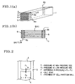
- Figs. 1(a), 1(b) show an embodiment of a honeycomb type gas separating membrane structure of the present invention. Fig. 1(a) is a schematic perspective view, and Fig. 1(b) is a sectional view along the line A-A of Fig. 1(a).
- Fig. 2 is an explanatory view about a model of a beam structure supported at both ends of a honeycomb type gas separating membrane structure of the present invention.
- Figs. 3(a), 3(b) are schematic front views showing each embodiment of disposition of gas flow passages in a honeycomb type gas separating membrane structure of the present invention.
- Figs. 4(a), 4(b) are schematic front views showing each embodiment of shapes of a honeycomb type gas separating membrane structure of the present invention. Fig. 4(a) is the case of a square, and Fig. 4(b) is the case of a circle.
- Figs. 5(a), 5(b), and 5(c) are explanatory views showing an embodiment of a production process of a honeycomb type gas separating membrane structure of the present invention.
- Fig. 6 is a schematic block diagram showing an embodiment of an apparatus for performance evaluation test of a honeycomb type gas separating membrane structure used in Example.
-
- A honeycomb type gas separating membrane structure of the present invention has a honeycomb unitary structure and is a dense body made of a material having a gas separation ability.
- According to the honeycomb type gas separating membrane structure, a support for supporting a gas separating membrane is unnecessary, and the membrane area can be enlarged, and cost is reduced because the production process is simple.
- Further, it is possible in the present invention to apply a catalyst powder mixed with a solvent to promote surface reaction to each of a raw material gas side and a permeated gas side of a honeycomb type gas separating membrane structure by slurry-coating, dip-coating, or the like, and subjected to a heat treatment. The catalyst does not have to be dense, and the production process is very easy in comparison to forming of a function membrane.
- From the above, a honeycomb type gas separating membrane structure of the present invention can be applied to an oxygen permeable membrane using a mixed conductive material represented by perovskite oxide, layered perovskite oxide, zirconia where a metal is dispersed, or the like, a hydrogen permeable membrane using a proton conductive material oxide, a hydrocarbon selectively-permeating membrane using zeolite, or the like. However any gas separating membrane structure can be applied to such membrane as long as it is a dense material having a gas separation ability. By a dense body here is meant a body which does not contain through-pores for gas passage. The component being separated from the mixed gas passes through the solid material of the dense body.
- The present invention is hereinbelow described in detail on the basis of drawings.
- Figs. 1(a), 1(b) show an embodiment of a honeycomb type gas separating membrane structure of the present invention. Fig. 1(a) is a schematic perspective view, and Fig. 1(b) is a sectional view along the line A-A of Fig. 1(a).
- An embodiment of a honeycomb separator membrane structure of the present invention is a square-section honeycomb type gas separating
membrane structure 1 having a plurality ofparallel cell passages 4 for gas flow as shown in Fig. 1. The flow passages are in two sets, i.e. gas flow passages of a raw material gas side and gas flow passages of a permeated gas side. The cell passages of the two sets are disposed so that the respective gas flows are parallel and in mutually opposite directions. - In one of the sets of gas flow passages, the
cell passages 4 are sealed with asealing material 6 at both ends thereof.Slits membrane structure 1 corresponding to the sealedcell passage 4 so as to pass through the side face of thecell passge 4 as shown in Fig. 1(b). Thegas flow passages 5 of the other set are open at the opposite ends for straight flow through in the longitudinal direction of the honeycomb body. - By this, a gas on the raw material gas side or the permeated gas side can stay for a sufficient time in the gas flow passage, and therefore a gas contact efficiency on the raw material gas side and the permeated gas side can be improved.
- The main characteristic of a honeycomb type gas separating membrane structure of the present invention is that a gas separating membrane itself is formed to have a dense honeycomb structure.
- This enables the gas separating membrane itself to support its own weight, thereby a support for supporting the gas separating membrane is unnecessary. Therefore, the production process can be simplified and the cost can be reduced in comparison with a conventional gas separating membrane having a stratified structure.
- Further, a thickness of a cell partition wall and a cell span of the above honeycomb structure can be easily optimized in accordance with a difference in pressure between the raw material gas side and the permeated gas side.
- In a honeycomb type gas separating membrane structure of the present invention, a cell partition wall between the raw material gas side and the permeated gas side preferable has a thickness of 50 - 500 µm.
- In more detail, in the case that there is almost no difference in pressure between the raw material gas side and the permeated gas side, a thickness of a cell partition wall and a cell pitch can be freely selected.
- For example, the cell partition wall may be thinned to about 50 µm which does not give any pinhole.
- On the other hand, when there is a difference in pressure between the raw material gas side and the permeated gas side, it is necessary to select a thickness of the cell partition wall and a cell pitch according to the difference in pressure.
- For example, in the case of a model having a beam structure supported at both ends as shown in Fig. 2, a necessary strength of a material to apply difference P in pressure to the thickness h of the cell partition wall and the
cell span 1 can be calculated by the use of the formula: - In the case that the difference in pressure between the raw material gas side and the permeated gas side is 50 atm. and that the material strength is 100 MPa, it is required that the cell pitch is 1.3 mm or less to obtain a cell partition wall having a thickness of 200 µm and that the cell pitch is 4 mm or less to obtain a cell partition wall having a thickness of 500 µm according to the above formula.
- In a honeycomb type gas separating membrane structure of the present invention, it is not required that a sectional area of a gas flow passage on the raw material gas side is the same as that on the permeated gas side, and the sectional areas can be freely adjusted in consideration of reaction speed, flow rate, and the case of having a difference in pressure between the raw material gas side and the permeated gas side (see Figs. 3(a), 3(b)).
- For example, in the case that there is a difference in pressure between the raw material gas side and the permeated gas side, as shown in Fig. 3(b), a cell span can be widened with regard to partition walls which are not positioned between the raw material gas side and the permeated gas side.
- It is not required to give all the partition walls the same thickness. The partition walls between the raw material gas side and the permeated gas side are required to be as thin as possible, and the other walls can be suitably thickened without problem in view of strength upon production.
- Further, a shape of a honeycomb type gas separating membrane structure of the present invention is preferably square or circular as shown in Figs. 4(a) and 4(b).
- In the case that the shape is square (see Fig. 4 (a)), the surface area can be effectively used, and filling density can be increased in the case that a plurality of membrane structures constitute a module.
- On the other hand, in the case that the shape is circular (see Fig. 4(b)), sealing is easy, the structure is strong against external impact.
- The cell shape of a honeycomb type gas separating membrane structure of the present invention is not particularly limited, and for example, circular, square, or hexagonal shape, or a mixture of these shapes may be suitably employed. In the case that permeation area on the raw material gas side and the permeated gas side are made large, it is preferable to employ square mainly.
- A material having a gas separation ability used in the present invention depends on kind of gas to be separated. For example, in the case that oxygen is permeated, La-Sr-Co-Fe-O, which has a perovskite structure, is representative. However, the material may have various compositions (see Terada et.al. Journal of Japan Chemistry Organization 1988, No.7, pp1084).
- In addition, there is known as such a material Sr-Fe-Co-O, which is a stable material even in a reducing atmosphere and which has a layered perovskite structure, or the like.
- The present invention is hereinbelow described in more detail with reference to Example. However, the present invention is by no means limited to these Examples.
- Strontium carbonate, cobalt carbonate and iron nitrate are weighed to give stoichiometric ratio (SrCo0.8Fe0.2), dissolved in water, subjected to evaporation with being stirred, and then calcined for 10 hours at 850°C in air to obtain a calcined powder. It was confirmed by an X-ray diffraction method that the obtained calcined powder has a single phase perovskite structure.
- The aforementioned calcined powder was ground in a ball mill and subjected to sieving to obtain a powder having average particle size of about 0.8 µm. To the calcined powder were added 5% by weight of methyl cellulose (binder) and 30% by weight of water in reference to weight of the solid content of the calcined powder to obtain a mixture.
- The mixture was subjected to kneading and then extrusion molding to obtain a honeycomb compact 10 having dimensions of 35 mm diameter × 10 cmL (see Fig. 5(a)). A sealing
material 6 having the same components as the calcined powder was applied to both end surfaces of the honeycomb compact by brushing on every other line for sealing. Only a peripheral wall had a thickness of 1 mm. - Then, the honeycomb compact was fired for 5 hours at 1250°C in the atmosphere to obtain a honeycomb fired body 12(Fig. 5(b)).
- In the obtained honeycomb fired
body 12, an apparent density was 95%, a thickness of a cell partition wall was 200 µm, a cell span was 3 mm, and the number of cells was 10 cell × 10 cell. - Finally, slits 8a, 8b were formed by cutting so as to pass through the side surface of the
cell passage 4 on a side surface of the honeycomb firedbody 12 corresponding to the sealedcell passage 4 as shown in Fig. 1(b) to obtain a honeycomb type gas separatingmembrane structure 1 shown in Fig. 5(c). - Then, a performance evaluation test of the honeycomb type gas separating membrane structure was performed using an apparatus shown in Fig. 6.
- A vitreous powder was applied in peripheral portions of the upper and lower ends of the honeycomb type gas separating
membrane structure 1, which was then brought into contact with square-shapedalumina tubes 20a and 20b and pressed by the mechanical force of a spring. In such a condition, the honeycomb type gas separatingmembrane structure 1 was perpendicularly disposed inside aquartz tube 24 in anelectric furnace 28. - The gap between the honeycomb type gas separating
membrane structure 1 and thequartz tube 24 was filled with aquartz wool 26. - They were arranged so that air in the
quartz tube 24 flows mainly into the honeycomb type gas separatingmembrane structure 1. - The vitreous powder was molten at a high temperature to work as glass seals 22a and 22b to seal the upper and lower ends of the honeycomb type gas separating
membrane structure 1 and thealumina tubes 20a and 20b. - Next, as shown in Fig. 6, He gas was introduced from upside to downside of the honeycomb type gas separating
membrane structure 1 on the side of cell passage 4 (the side of permeated gas) at a rate of 20 Nl/mm. With circulating air from the bottom to the top of the side of the slit 8 (raw material gas side) disposed on the side surface of the honeycomb type gas separatingmembrane structure 1, the honeycomb type gas separatingmembrane structure 1 was measured for permeation of oxygen and leakage of air at the time that theelectric furnace 28 was heated up to 850°C at the rate of 10°C/min. - As a result, the (average) permeation of oxygen was 6.5Nml/min·cm2.
- With regard to the leakage of air of the honeycomb type gas separating membrane structure, nitrogen concentration in the permeated gas was 0.01% or less by a gas chromatography, and no leakage of air was confirmed.
- The (average) permeation of oxygen of the honeycomb type gas separating membrane structure was determined by measuring oxygen concentration of He gas in the discharge port on the permeated gas side by an oxygen sensor.
- In a honeycomb type gas separating membrane structure of the present invention, a support for supporting a gas separating membrane is unnecessary, and the membrane area can be enlarged, and cost is reduced because the production process is simple.
Claims (4)
- A honeycomb type gas separating membrane structure for separating or supplying a specified gas from a mixed gas, wherein the gas separating membrane structure has a honeycomb unitary structure and is a dense body made of a material having a gas separation ability.
- A honeycomb type gas separating membrane structure according to claim 1, wherein a cell partition wall between a raw material gas side and a permeated gas side of the honeycomb type gas separating membrane structure has a thickness of 50 - 500 µm.
- A honeycomb type gas separating membrane structure according to claim 1 or 2, wherein the gas flow passage or passages on the raw material gas side and the gas flow passage or passages on the permeated gas side are disposed so that they are parallel and the respective gas flows are in opposite directions through the honeycomb structure.
- A method of separating or supplying a specified gas from a gas mixture, comprising passing the specified gas through a membrane which has a honeycomb unitary structure and is a dense body made of a material having gas separation capability for said specified gas.
Applications Claiming Priority (2)
| Application Number | Priority Date | Filing Date | Title |
|---|---|---|---|
| JP28597199 | 1999-10-06 | ||
| JP28597199A JP2001104742A (en) | 1999-10-06 | 1999-10-06 | Honeycomb type gas separation membrane structure |
Publications (2)
| Publication Number | Publication Date |
|---|---|
| EP1090671A1 true EP1090671A1 (en) | 2001-04-11 |
| EP1090671B1 EP1090671B1 (en) | 2004-06-23 |
Family
ID=17698349
Family Applications (1)
| Application Number | Title | Priority Date | Filing Date |
|---|---|---|---|
| EP00308602A Expired - Lifetime EP1090671B1 (en) | 1999-10-06 | 2000-09-29 | Honeycomb type gas separating membrane |
Country Status (5)
| Country | Link |
|---|---|
| US (1) | US6461406B1 (en) |
| EP (1) | EP1090671B1 (en) |
| JP (1) | JP2001104742A (en) |
| DE (1) | DE60011724T2 (en) |
| NO (1) | NO20005055L (en) |
Cited By (3)
| Publication number | Priority date | Publication date | Assignee | Title |
|---|---|---|---|---|
| EP1670559A4 (en) * | 2003-10-01 | 2008-07-30 | Ceramem Corp | Membrane devices with controlled transmembrane pressure and method of use |
| WO2008132521A3 (en) * | 2007-04-25 | 2009-03-19 | Helbio S A Hydrogen And Energy | Device for separation and purification of hydrogen from reformate gases and method of production thereof |
| EP4417298A4 (en) * | 2022-08-02 | 2025-08-06 | Ngk Insulators Ltd | SEPARATION MEMBRANE MODULE |
Families Citing this family (8)
| Publication number | Priority date | Publication date | Assignee | Title |
|---|---|---|---|---|
| US20060090649A1 (en) * | 2004-10-29 | 2006-05-04 | Wei Liu | High separation area membrane module |
| US7169213B2 (en) * | 2004-10-29 | 2007-01-30 | Corning Incorporated | Multi-channel cross-flow porous device |
| WO2009134359A1 (en) * | 2008-04-28 | 2009-11-05 | Corning Incorporated | Monolith membrane module for liquid filtration |
| EP2334423B1 (en) | 2008-08-30 | 2017-03-01 | Corning Incorporated | Methods and devices for fluid handling |
| JP6247040B2 (en) * | 2013-07-30 | 2017-12-13 | ダイハツ工業株式会社 | Fuel cell system |
| DE102013013197A1 (en) | 2013-08-09 | 2015-02-12 | Bundesrepublik Deutschland, vertreten durch das Bundesministerium für Wirtschaft und Arbeit, dieses vertreten durch den Präsidenten der Physikalisch-Technischen Bundesanstalt Braunschweig und Berlin | A method and apparatus for cryogen-free concentration of a hyperpolarized gas in a continuously flowing gas stream and use |
| JP6373696B2 (en) * | 2014-09-19 | 2018-08-15 | 日本碍子株式会社 | Thermal / sonic conversion parts and thermal / sonic conversion units |
| JP7097294B2 (en) * | 2016-03-31 | 2022-07-07 | 日本碍子株式会社 | Monolith type separation membrane structure |
Citations (3)
| Publication number | Priority date | Publication date | Assignee | Title |
|---|---|---|---|---|
| US5034023A (en) * | 1989-12-21 | 1991-07-23 | Corning Incorporated | Ceramic honeycomb structures as oxygen separators or concentrators |
| GB2257054A (en) * | 1991-07-04 | 1993-01-06 | Normalair Garrett | Oxygen generating system |
| US5611931A (en) * | 1995-07-31 | 1997-03-18 | Media And Process Technology Inc. | High temperature fluid separations using ceramic membrane device |
Family Cites Families (10)
| Publication number | Priority date | Publication date | Assignee | Title |
|---|---|---|---|---|
| BE788610A (en) * | 1971-09-09 | 1973-03-08 | Rhone Poulenc Sa | MEMBRANE SEPARATOR APPARATUS USED IN GAS PERMEATION AND PERVAPORATION |
| JPS5343153A (en) | 1976-09-30 | 1978-04-19 | Masayasu Negishi | Heat engine |
| JPS5948135A (en) * | 1982-09-13 | 1984-03-19 | Kobe Kosan Kk | Integral molding of cassette for magnetic tape and molding machine employed therefor |
| US5149340A (en) * | 1991-03-12 | 1992-09-22 | Marathon Oil Company | Process and apparatus for separating impurities from hydrocarbons |
| JPH0767528A (en) | 1992-08-06 | 1995-03-14 | Seiwa Kasei Kk | How to maintain the freshness of fruits and vegetables |
| US5298341A (en) * | 1992-08-20 | 1994-03-29 | Cerramatec, Inc. | Multiple stack ion conducting devices |
| US5356728A (en) | 1993-04-16 | 1994-10-18 | Amoco Corporation | Cross-flow electrochemical reactor cells, cross-flow reactors, and use of cross-flow reactors for oxidation reactions |
| JP3599370B2 (en) | 1994-05-23 | 2004-12-08 | 日本碍子株式会社 | Hydrogen production equipment |
| US6077436A (en) * | 1997-01-06 | 2000-06-20 | Corning Incorporated | Device for altering a feed stock and method for using same |
| JPH11179167A (en) * | 1997-12-25 | 1999-07-06 | Nitto Denko Corp | Spiral type membrane module |
-
1999
- 1999-10-06 JP JP28597199A patent/JP2001104742A/en active Pending
-
2000
- 2000-09-22 US US09/667,930 patent/US6461406B1/en not_active Expired - Lifetime
- 2000-09-29 EP EP00308602A patent/EP1090671B1/en not_active Expired - Lifetime
- 2000-09-29 DE DE60011724T patent/DE60011724T2/en not_active Expired - Lifetime
- 2000-10-06 NO NO20005055A patent/NO20005055L/en not_active Application Discontinuation
Patent Citations (3)
| Publication number | Priority date | Publication date | Assignee | Title |
|---|---|---|---|---|
| US5034023A (en) * | 1989-12-21 | 1991-07-23 | Corning Incorporated | Ceramic honeycomb structures as oxygen separators or concentrators |
| GB2257054A (en) * | 1991-07-04 | 1993-01-06 | Normalair Garrett | Oxygen generating system |
| US5611931A (en) * | 1995-07-31 | 1997-03-18 | Media And Process Technology Inc. | High temperature fluid separations using ceramic membrane device |
Cited By (4)
| Publication number | Priority date | Publication date | Assignee | Title |
|---|---|---|---|---|
| EP1670559A4 (en) * | 2003-10-01 | 2008-07-30 | Ceramem Corp | Membrane devices with controlled transmembrane pressure and method of use |
| US7854846B2 (en) | 2003-10-01 | 2010-12-21 | Ceramem Corporation | Membrane devices with controlled transmembrane pressure and method of use |
| WO2008132521A3 (en) * | 2007-04-25 | 2009-03-19 | Helbio S A Hydrogen And Energy | Device for separation and purification of hydrogen from reformate gases and method of production thereof |
| EP4417298A4 (en) * | 2022-08-02 | 2025-08-06 | Ngk Insulators Ltd | SEPARATION MEMBRANE MODULE |
Also Published As
| Publication number | Publication date |
|---|---|
| EP1090671B1 (en) | 2004-06-23 |
| US6461406B1 (en) | 2002-10-08 |
| NO20005055D0 (en) | 2000-10-06 |
| JP2001104742A (en) | 2001-04-17 |
| NO20005055L (en) | 2001-04-09 |
| DE60011724T2 (en) | 2005-07-21 |
| DE60011724D1 (en) | 2004-07-29 |
Similar Documents
| Publication | Publication Date | Title |
|---|---|---|
| EP0732138B1 (en) | Planar solid-state membrane module | |
| CA2385668C (en) | Membrane and use thereof | |
| EP1090671B1 (en) | Honeycomb type gas separating membrane | |
| EP0661088B1 (en) | Cordierite ceramic filter and method of producing the same | |
| US5938992A (en) | Production method of thin wall cordierite honeycomb structure | |
| EA016090B1 (en) | Control of kinetic decomposition in mixed conducting ion transport membranes | |
| JP3067740B2 (en) | Ceramic filter module | |
| US11642661B2 (en) | Supported catalyst for organic substance decomposition and organic substance decomposition device | |
| Etchegoyen et al. | An architectural approach to the oxygen permeability of a La0. 6Sr0. 4Fe0. 9Ga0. 1O3− δ perovskite membrane | |
| EP0592809A1 (en) | Composite mixed conductor membranes for producing oxygen | |
| US7169213B2 (en) | Multi-channel cross-flow porous device | |
| EP1289626A4 (en) | Composite ceramic membrane oxygen separation method | |
| EP1048613A1 (en) | Hydrogen permeation through mixed protonic-electronic conducting materials | |
| CN103987681A (en) | Composite oxygen transport membrane | |
| US20190331435A1 (en) | Heat storage reactor | |
| JPS6146401B2 (en) | ||
| EP1634859A1 (en) | Porous material and method for preparation thereof, and honeycomb structure | |
| Ren et al. | A rational asymmetric hollow fiber membrane for oxygen permeation | |
| EP0994083B1 (en) | Ceramic laminate material | |
| EP1090672A1 (en) | Honeycomb type gas separating membrane structure | |
| EP0732306B2 (en) | Novel compositions capable of operating under high carbon dioxide partial pressures for use in solid-state oxygen producing devices | |
| JP2004290838A (en) | Fluid separation filter and fluid separation module | |
| KR101146137B1 (en) | Oxygen permeable tube and Manufacturing method thereof | |
| EP0732305A1 (en) | Novel compositions capable of operating under high oxygan partial pressures for use in solid-state oxygen producing devices | |
| JPH0246544B2 (en) |
Legal Events
| Date | Code | Title | Description |
|---|---|---|---|
| PUAI | Public reference made under article 153(3) epc to a published international application that has entered the european phase |
Free format text: ORIGINAL CODE: 0009012 |
|
| AK | Designated contracting states |
Kind code of ref document: A1 Designated state(s): DE FR GB NL |
|
| AX | Request for extension of the european patent |
Free format text: AL;LT;LV;MK;RO;SI |
|
| 17P | Request for examination filed |
Effective date: 20011004 |
|
| AKX | Designation fees paid |
Free format text: DE FR GB NL |
|
| 17Q | First examination report despatched |
Effective date: 20030407 |
|
| GRAP | Despatch of communication of intention to grant a patent |
Free format text: ORIGINAL CODE: EPIDOSNIGR1 |
|
| GRAS | Grant fee paid |
Free format text: ORIGINAL CODE: EPIDOSNIGR3 |
|
| GRAA | (expected) grant |
Free format text: ORIGINAL CODE: 0009210 |
|
| AK | Designated contracting states |
Kind code of ref document: B1 Designated state(s): DE FR GB NL |
|
| REG | Reference to a national code |
Ref country code: GB Ref legal event code: FG4D |
|
| REF | Corresponds to: |
Ref document number: 60011724 Country of ref document: DE Date of ref document: 20040729 Kind code of ref document: P |
|
| ET | Fr: translation filed | ||
| PLBE | No opposition filed within time limit |
Free format text: ORIGINAL CODE: 0009261 |
|
| STAA | Information on the status of an ep patent application or granted ep patent |
Free format text: STATUS: NO OPPOSITION FILED WITHIN TIME LIMIT |
|
| 26N | No opposition filed |
Effective date: 20050324 |
|
| REG | Reference to a national code |
Ref country code: FR Ref legal event code: PLFP Year of fee payment: 17 |
|
| REG | Reference to a national code |
Ref country code: FR Ref legal event code: PLFP Year of fee payment: 18 |
|
| REG | Reference to a national code |
Ref country code: FR Ref legal event code: PLFP Year of fee payment: 19 |
|
| PGFP | Annual fee paid to national office [announced via postgrant information from national office to epo] |
Ref country code: FR Payment date: 20180813 Year of fee payment: 19 Ref country code: NL Payment date: 20180815 Year of fee payment: 19 Ref country code: DE Payment date: 20180918 Year of fee payment: 19 |
|
| PGFP | Annual fee paid to national office [announced via postgrant information from national office to epo] |
Ref country code: GB Payment date: 20180926 Year of fee payment: 19 |
|
| REG | Reference to a national code |
Ref country code: DE Ref legal event code: R119 Ref document number: 60011724 Country of ref document: DE |
|
| REG | Reference to a national code |
Ref country code: NL Ref legal event code: MM Effective date: 20191001 |
|
| PG25 | Lapsed in a contracting state [announced via postgrant information from national office to epo] |
Ref country code: DE Free format text: LAPSE BECAUSE OF NON-PAYMENT OF DUE FEES Effective date: 20200401 Ref country code: NL Free format text: LAPSE BECAUSE OF NON-PAYMENT OF DUE FEES Effective date: 20191001 |
|
| GBPC | Gb: european patent ceased through non-payment of renewal fee |
Effective date: 20190929 |
|
| PG25 | Lapsed in a contracting state [announced via postgrant information from national office to epo] |
Ref country code: FR Free format text: LAPSE BECAUSE OF NON-PAYMENT OF DUE FEES Effective date: 20190930 Ref country code: GB Free format text: LAPSE BECAUSE OF NON-PAYMENT OF DUE FEES Effective date: 20190929 |