EP1090667A1 - Drain valve for fuel filter water separator - Google Patents
Drain valve for fuel filter water separator Download PDFInfo
- Publication number
- EP1090667A1 EP1090667A1 EP20000308733 EP00308733A EP1090667A1 EP 1090667 A1 EP1090667 A1 EP 1090667A1 EP 20000308733 EP20000308733 EP 20000308733 EP 00308733 A EP00308733 A EP 00308733A EP 1090667 A1 EP1090667 A1 EP 1090667A1
- Authority
- EP
- European Patent Office
- Prior art keywords
- port
- drain
- vent
- drain valve
- piston
- Prior art date
- Legal status (The legal status is an assumption and is not a legal conclusion. Google has not performed a legal analysis and makes no representation as to the accuracy of the status listed.)
- Granted
Links
- XLYOFNOQVPJJNP-UHFFFAOYSA-N water Substances O XLYOFNOQVPJJNP-UHFFFAOYSA-N 0.000 title claims abstract description 90
- 239000000446 fuel Substances 0.000 title claims abstract description 67
- 230000013011 mating Effects 0.000 claims abstract description 12
- 230000000903 blocking effect Effects 0.000 claims abstract description 10
- 238000002485 combustion reaction Methods 0.000 claims abstract description 7
- 239000007921 spray Substances 0.000 claims abstract description 6
- 238000011144 upstream manufacturing Methods 0.000 claims description 56
- 238000007789 sealing Methods 0.000 description 8
- 239000002283 diesel fuel Substances 0.000 description 7
- 239000013618 particulate matter Substances 0.000 description 4
- 230000000694 effects Effects 0.000 description 2
- 238000002347 injection Methods 0.000 description 2
- 239000007924 injection Substances 0.000 description 2
- 239000004215 Carbon black (E152) Substances 0.000 description 1
- 230000007797 corrosion Effects 0.000 description 1
- 238000005260 corrosion Methods 0.000 description 1
- 238000001914 filtration Methods 0.000 description 1
- 238000010438 heat treatment Methods 0.000 description 1
- 229930195733 hydrocarbon Natural products 0.000 description 1
- 150000002430 hydrocarbons Chemical class 0.000 description 1
- 239000012535 impurity Substances 0.000 description 1
- JEIPFZHSYJVQDO-UHFFFAOYSA-N iron(III) oxide Inorganic materials O=[Fe]O[Fe]=O JEIPFZHSYJVQDO-UHFFFAOYSA-N 0.000 description 1
- 239000007788 liquid Substances 0.000 description 1
- 230000014759 maintenance of location Effects 0.000 description 1
- 230000007257 malfunction Effects 0.000 description 1
- 238000012986 modification Methods 0.000 description 1
- 230000004048 modification Effects 0.000 description 1
- 230000000717 retained effect Effects 0.000 description 1
Images







Classifications
-
- B—PERFORMING OPERATIONS; TRANSPORTING
- B01—PHYSICAL OR CHEMICAL PROCESSES OR APPARATUS IN GENERAL
- B01D—SEPARATION
- B01D36/00—Filter circuits or combinations of filters with other separating devices
- B01D36/001—Filters in combination with devices for the removal of gas, air purge systems
-
- B—PERFORMING OPERATIONS; TRANSPORTING
- B01—PHYSICAL OR CHEMICAL PROCESSES OR APPARATUS IN GENERAL
- B01D—SEPARATION
- B01D17/00—Separation of liquids, not provided for elsewhere, e.g. by thermal diffusion
- B01D17/005—Separation of liquids, not provided for elsewhere, e.g. by thermal diffusion by thermal diffusion
-
- B—PERFORMING OPERATIONS; TRANSPORTING
- B01—PHYSICAL OR CHEMICAL PROCESSES OR APPARATUS IN GENERAL
- B01D—SEPARATION
- B01D17/00—Separation of liquids, not provided for elsewhere, e.g. by thermal diffusion
- B01D17/02—Separation of non-miscible liquids
- B01D17/0208—Separation of non-miscible liquids by sedimentation
-
- B—PERFORMING OPERATIONS; TRANSPORTING
- B01—PHYSICAL OR CHEMICAL PROCESSES OR APPARATUS IN GENERAL
- B01D—SEPARATION
- B01D17/00—Separation of liquids, not provided for elsewhere, e.g. by thermal diffusion
- B01D17/02—Separation of non-miscible liquids
- B01D17/0208—Separation of non-miscible liquids by sedimentation
- B01D17/0214—Separation of non-miscible liquids by sedimentation with removal of one of the phases
-
- B—PERFORMING OPERATIONS; TRANSPORTING
- B01—PHYSICAL OR CHEMICAL PROCESSES OR APPARATUS IN GENERAL
- B01D—SEPARATION
- B01D17/00—Separation of liquids, not provided for elsewhere, e.g. by thermal diffusion
- B01D17/08—Thickening liquid suspensions by filtration
- B01D17/10—Thickening liquid suspensions by filtration with stationary filtering elements
-
- B—PERFORMING OPERATIONS; TRANSPORTING
- B01—PHYSICAL OR CHEMICAL PROCESSES OR APPARATUS IN GENERAL
- B01D—SEPARATION
- B01D35/00—Filtering devices having features not specifically covered by groups B01D24/00 - B01D33/00, or for applications not specifically covered by groups B01D24/00 - B01D33/00; Auxiliary devices for filtration; Filter housing constructions
- B01D35/18—Heating or cooling the filters
-
- B—PERFORMING OPERATIONS; TRANSPORTING
- B01—PHYSICAL OR CHEMICAL PROCESSES OR APPARATUS IN GENERAL
- B01D—SEPARATION
- B01D36/00—Filter circuits or combinations of filters with other separating devices
- B01D36/003—Filters in combination with devices for the removal of liquids
-
- F—MECHANICAL ENGINEERING; LIGHTING; HEATING; WEAPONS; BLASTING
- F02—COMBUSTION ENGINES; HOT-GAS OR COMBUSTION-PRODUCT ENGINE PLANTS
- F02M—SUPPLYING COMBUSTION ENGINES IN GENERAL WITH COMBUSTIBLE MIXTURES OR CONSTITUENTS THEREOF
- F02M37/00—Apparatus or systems for feeding liquid fuel from storage containers to carburettors or fuel-injection apparatus; Arrangements for purifying liquid fuel specially adapted for, or arranged on, internal-combustion engines
- F02M37/22—Arrangements for purifying liquid fuel specially adapted for, or arranged on, internal-combustion engines, e.g. arrangements in the feeding system
- F02M37/24—Arrangements for purifying liquid fuel specially adapted for, or arranged on, internal-combustion engines, e.g. arrangements in the feeding system characterised by water separating means
- F02M37/26—Arrangements for purifying liquid fuel specially adapted for, or arranged on, internal-combustion engines, e.g. arrangements in the feeding system characterised by water separating means with water detection means
-
- F—MECHANICAL ENGINEERING; LIGHTING; HEATING; WEAPONS; BLASTING
- F02—COMBUSTION ENGINES; HOT-GAS OR COMBUSTION-PRODUCT ENGINE PLANTS
- F02M—SUPPLYING COMBUSTION ENGINES IN GENERAL WITH COMBUSTIBLE MIXTURES OR CONSTITUENTS THEREOF
- F02M37/00—Apparatus or systems for feeding liquid fuel from storage containers to carburettors or fuel-injection apparatus; Arrangements for purifying liquid fuel specially adapted for, or arranged on, internal-combustion engines
- F02M37/22—Arrangements for purifying liquid fuel specially adapted for, or arranged on, internal-combustion engines, e.g. arrangements in the feeding system
- F02M37/32—Arrangements for purifying liquid fuel specially adapted for, or arranged on, internal-combustion engines, e.g. arrangements in the feeding system characterised by filters or filter arrangements
-
- B—PERFORMING OPERATIONS; TRANSPORTING
- B01—PHYSICAL OR CHEMICAL PROCESSES OR APPARATUS IN GENERAL
- B01D—SEPARATION
- B01D2201/00—Details relating to filtering apparatus
- B01D2201/16—Valves
- B01D2201/167—Single-way valves
-
- Y—GENERAL TAGGING OF NEW TECHNOLOGICAL DEVELOPMENTS; GENERAL TAGGING OF CROSS-SECTIONAL TECHNOLOGIES SPANNING OVER SEVERAL SECTIONS OF THE IPC; TECHNICAL SUBJECTS COVERED BY FORMER USPC CROSS-REFERENCE ART COLLECTIONS [XRACs] AND DIGESTS
- Y10—TECHNICAL SUBJECTS COVERED BY FORMER USPC
- Y10T—TECHNICAL SUBJECTS COVERED BY FORMER US CLASSIFICATION
- Y10T137/00—Fluid handling
- Y10T137/8593—Systems
- Y10T137/86292—System with plural openings, one a gas vent or access opening
- Y10T137/86324—Tank with gas vent and inlet or outlet
- Y10T137/86332—Vent and inlet or outlet in unitary mounting
Definitions
- the invention relates to fuel filter water separators for internal combustion engines, usually diesel engines, and more particularly to a drain valve therefor.
- Diesel fuel tends to contain relatively high levels of impurities such as particulate matter and water, as compared to corresponding levels in other liquid hydrocarbon fuels. As a consequence, diesel fuel typically needs to be filtered before injecting the diesel fuel into the engine. The concern over the levels of particulate matter and water in the diesel fuel are significant due to the problems which can be caused. Particulate matter can clog fuel lines and fuel injectors and cause deposits to be formed in the combustion chamber. When water-laden diesel fuel is run through a fuel system and engine, the presence of the water can cause the fuel injection system to malfunction due to rust, corrosion, deposits, etc. Excessive levels of water may lead to catastrophic injector nozzle failure due to the effects of steam expansion and/or lubricity effects.
- Fuel filter water separators are known in the prior art for filtering the particulate matter and removing the water. Fuel filter water separators with a drain valve for periodically draining the collected water are also known in the prior art, for example as shown in U.S. Patent 5,855,772, incorporated herein by reference.
- the present invention provides an improved drain valve for a fuel filter water separator.
- the fuel filter water separator has a housing defining a water collection space and a vent space.
- the housing has a wall with a drain opening therethrough for draining water from the water collection space, and a vent opening therethrough and permitting incoming air to replace outgoing water.
- the engine has a running condition wherein the fuel filter water separator is pressurized, and an off condition wherein the fuel filter water separator is not pressurized.
- the drain valve includes a housing mounted to the fuel filter water separator housing and having a first port mating with the vent opening, a second port mating with the drain opening, and a third port.
- An actuator member in the drain valve housing is actuatable between a closed position blocking communication of the first port with the third port and blocking communication of the second port with the third port.
- the actuator member in the drain valve housing is actuatable to an open position providing communication of the first port with the third port and providing communication of the second port with the third port.
- the operator sees an indication that water is present, he turns off the engine, thus depressurizing the fuel filter water separator, and opens the drain valve by actuating the actuator member to the open position, and collected water and vent air each flow through the noted third port, but in opposite directions, i.e., if the operator opens the drain valve during the off condition of the engine with the fuel filter water separator not pressurized, the first port draws air through the vent passage from around the drain stream of collected water flowing in the opposite direction in the third port.
- the actuator member of the drain valve is actuated to the open position when the engine is in the running condition and providing pressurized fuel at the noted vent opening, then fuel spray from the vent opening and collected water from the drain opening of the fuel filter water separator housing each flow through the noted third port in the same direction, i.e. if the operator opens the drain valve during the running condition of the engine with the fuel filter water separator pressurized, a pressurized fuel vent stream from the first port joins the drain stream from the second port at the third port and flows in the same direction therethrough.
- a drain valve for a fuel filter water separator for an internal combustion engine said fuel filter water separator having a housing defining a water collection space and a vent space, the housing having a wall with a drain opening therethrough for draining water from said water collection space, and having a vent opening therethrough and permitting incoming air to replace outgoing water, said engine having a running condition wherein said fuel filter water separator is pressurized, said engine having an off condition wherein said fuel filter water separator is not pressurized
- said drain valve comprising a housing mounted to said fuel filter water separator housing and having a first port mating with said vent opening, a second port mating with said drain opening, and a third port, and an actuator member in said drain valve housing and actuable between a closed position blocking communication of said first port with said third port and blocking communication of said second port with said third port, and an open position providing communication of said first port with said third port and providing communication of said second port with said third port such that if said actuator member of said drain valve is
- a preferred form of drain valve which embodies this invention may have one or more of the following features.
- the third port may be gravitationally below the drain opening.
- the drain opening may be gravitationally below the vent opening.
- the third port may be gravitationally below the second port.
- the second port may be gravitationally below the first port.
- a seal radially bearing between the drain valve housing and the piston at the first port may be provided.
- a seal axially bearing between the drain valve housing and the piston at the third port may be provided.
- the first portion of the vent passage may extend between an upstream end and a downstream end, the upstream end communicating with the second portion of the vent passage when the piston is in the open position, the downstream end communicating with the first port when the piston is in the open position, the downstream end being blocked from communication with the first port when the piston is in the closed position.
- the upstream end of the first portion of the vent passage may communicate with the second portion of the vent passage when the piston is in the closed position.
- the first portion of the drain passage may extend between an upstream end and a downstream end, the upstream end communicating with the second port when the piston is in the open position, the second portion of the drain passage extending between an upstream end and a downstream end, the upstream end of the second portion of the drain passage communicating with the downstream end of the first portion of the drain passage in each of the open and closed positions of the piston, the downstream end of the second portion of the drain passage communicating with the third port when the piston is in the open position, at least one of the upstream ends of the first portion of the drain passage and the downstream end of the second portion of the drain passage being blocked from communication with a respective one of the second and third ports when the piston is in the closed position.
- the upstream end of the first portion of the drain passage may be blocked from communication with the second port when the piston is in the closed position.
- the downstream end of the second portion of the drain passage may communicate with the third port in each of the open and closed positions of the piston.
- the downstream end of the second portion of the drain passage may be blocked from communication with the third port when the piston is in the closed position.
- the upstream end of the first portion of the drain passage may communicate with the second port in each of the open and closed positions of the piston.
- An arcuate groove in one of the piston and the drain valve housing may communicate with the upstream end of the first portion of the drain passage and the second port in each of the open and closed positions of the piston.
- the vent passage may extend between an upstream end and a downstream end, the downstream end communicating with said first port when said piston is in the open position, the second portion of the vent passage extending between an upstream end and a downstream end, the upstream end of the second portion of the vent passage communicating with the third port when the piston is in the open position, the downstream end of the second portion of the vent passage communicating with the upstream end of the first portion of the vent passage in each of the open and closed positions of the piston, at least one of the downstream end of the first portion of the vent passage and the upstream end of the second portion of the vent passage being blocked from communication with a respective one of the first and third ports when the piston is in the closed position.
- the upstream end of the second portion of the vent passage may be in communication with the third port in each of the open and closed positions of the piston.
- the upstream end of the second portion of the vent passage may be blocked from communication with the third port when the piston is in the closed position.
- the downstream end of the first portion of the vent passage may be in communication with the first port in each of the open and closed positions of the piston.
- An arcuate groove in one of the piston and the drain valve may communicate with the downstream end of the first portion of the vent passage and the first port in each of the open and closed positions of the pistons.
- First and third seals which bear radially between the drain valve housing and the piston at the first and second ports at the radially extending first portions of the vent passage and drain passage respectively may be provided.
- First and second seals which bear axially between the drain valve housing and the piston at the third port at the axially extending positions of the vent passage and the drain passage respectively may be provided.
- the vent passage may have a third portion extending radially in the drain valve housing and a fourth portion extending axially in the drain valve housing, the second portion extending axially along the plunger, the first and third portions being joined by the second portion, the fourth portion being radially spaced from the second portion, the vent passage may have a fifth portion extending radially in the drain valve housing, such that vent air through the vent passage flows from the third port then through the fifth portion then axially through the fourth portion then radially through the third portion then axially through the second portion then radially through the first portion to the vent opening.
- the drain valve housing may have a drain chamber and a vent chamber axially spaced from each other by a dividing wall, and the plunger may extend axially through the dividing wall and may reciprocate in the drain and vent chambers between open and closed positions, such that in the open position, collected water flows from the drain chamber along the plunger into the third port, and vent air flows in the opposite direction through the third port towards the plunger and then enters the vent passage at the fifth portion.
- a drain passage having a first portion extending radially in the drain valve housing, relative to the axis and a second portion extending axially along the plunger to the third port may be provided.
- Fig. 1 shows a fuel filter water separator 70 and will be only briefly described since it is also shown at 20 in incorporated U.S. Patent 5,855,772 to which further reference may be had.
- Fuel filter water separator 70 includes a housing 72 closed by a threaded lid 74 and having a filter and water separating element 76 therein. Diesel fuel enters at fuel inlet 78, flows radially inwardly through annular filter element 76 to hollow interior 80 and then flows through fuel outlet 82 to the fuel injection system of internal combustion engine 84, such as a diesel engine.
- the housing includes a heater ring 86 for heating the diesel fuel to prevent it from coalescing in cold weather, a heater connector/thermostat assembly 88, and a water-in-fuel (WIF) sensor 90, all as is known in the prior art and as shown in the incorporated '772 patent.
- Housing 72 defines a water collection space 92 and a vent space 94.
- the housing has a wall 96 with a drain opening 98 therethrough for draining water from the water collection space.
- the wall has a vent opening 100 therethrough and permitting incoming air to replace outgoing water.
- the engine has a running condition wherein the fuel system including the fuel filter water separator is pressurized, and an off condition wherein the fuel system and fuel filter water separator is not pressurized.
- Drain valve 102 includes a housing 104, Fig. 2, mounted to fuel filter water separator housing 72 by bolts 106, 108, 110, 112, Figs. 2, 3, 12, 13, threaded into respective blind holes in increased thickness section 114 of the fuel filter water separator housing wall.
- the drain valve housing has a first port 116, Figs. 9 and 12 mating with vent opening 100.
- the drain valve housing has a second port 118, Figs. 9 and 13, mating with drain opening 98.
- the drain valve housing has a third port 120, Figs. 1 and 9, at the bottom thereof which is a combined vent and drain port and to which a drain hose 122, Figs. 2 and 3, may be connected at outer barbs 124 and retained by clamp 126.
- An actuator member 128 in drain valve housing 104 is actuatable between a closed position, Figs. 1-7, and an open position, Figs. 8-14.
- the closed position blocks communication of first port 116 with third port 120 and blocks communication of second port 118 with third port 120.
- the open position provides communication of first port 116 with third port 120 and provides communication of second port 118 with third port 120.
- actuator member 128 of drain valve 102 is actuated to the open position when the engine is in the noted off condition, collected water and vent air each flow through third port 120, but in opposite directions, Fig. 9, as shown at drain stream 130 and vent air stream 132.
- First port 116 draws air through the vent passage, to be described, from around drain stream 130 of collected water flowing in the opposite direction in third port 120.
- pressurized fuel spray from vent opening 100 and collected water from drain opening 98 of the fuel filter water separator housing each flow through third port 120 in the same direction as shown as fuel spray phantom arrow 134 and drain arrow 130, Fig. 9.
- a pressurized fuel vent stream 134 from first port 116 joins drain stream 130 from second port 118 at third port 120, and streams 134 and 130 flow in the same direction through port 120 to exit same, preferably through drain hose 122, Fig. 3.
- the drain valve has preferred vertical or gravitational orientation of the ports, particularly desirable for the noted non-pressurized drain cycle, i.e. with the engine in the noted off condition.
- Third port 120 is gravitationally below second port 118 which in turn is gravitationally below first port 116.
- Third port 120 is gravitationally below drain opening 98 which in turn is gravitationally below vent opening 100.
- actuator member 128 is a rotary piston 136 rotatable about a vertical axis 138.
- a vent passage 140, Figs. 2, 4, 9, 12 has a first portion 142, Figs. 4, 9, 12, extending radially through piston 136, relative to axis 138, and a second portion 144, Figs. 4, 9, 11, extending axially along a gap between piston 136 and drain valve housing 104.
- Fig. 9 such gap is between a flat surface 146, Figs. 11,12, on the outer surface of the piston, and a notched surface 148 on the inner cylindrical surface of the drain valve housing.
- First portion 142 of vent passage 140 extends between an upstream end 150 and a downstream end 152, Figs. 9 and 12.
- Second portion 144 of vent passage 140 extends between an upstream end 143, Fig. 9, and a downstream end 145.
- Downstream end 145 of second portion 144 is continuous with and in continuous communication with upstream end 150 of first portion 142, including in both of the noted open and closed positions.
- Downstream end 152 of first portion 142 communicates with first port 116 when piston 136 is in the noted open position, as shown in Figs. 9 and 12.
- Downstream end 152 is blocked from communication with first port 116 when piston 136 is in the noted closed position, Fig. 4.
- Piston 136 is preferably formed with a ball socket portion 156, Fig. 2, at vent port 140 to facilitate engagement with sealing grommet 154 and rotation of piston 136 while maintaining the seal.
- Upstream end 143 of second portion 144 of the vent passage is in communication with third port 120 in each of the open and closed positions of the piston.
- a drain passage 158, Figs. 2, 4, 9, 13, has a first portion 160, Figs. 4, 9, 13, extending radially in piston 136, relative to axis 138, and a second portion 162 extending axially in piston 136.
- First portion 160 extends between an upstream end 164 and a downstream end 166.
- Second portion 162 extends between an upstream end 168 and a downstream end 170.
- Upstream end 168 of second portion 162 is continuous with and in continuous communication with downstream end 166 of first potion 160 including in each of the noted open and closed positions of the piston.
- Downstream end 170 of second portion 162 is in communication with third port 120 in each of the open and closed positions of the piston.
- Upstream end 164 of first portion 160 is in communication with second port 118 when piston 136 is in the open position as shown in Figs. 9 and 13. Upstream end 164 is blocked from communication with second port 118 when piston 136 is in the closed position, as shown in Figs. 4 and 7.
- Piston 136 is provided with a second ball socket portion 174, Fig. 2, around drain passage 158 to facilitate and maintain the seal against sealing grommet 172 and to maintain such seal during rotation of piston 136.
- Drain valve 102 includes an manually engageable upper handle 176, Figs. 1 and 2, non-rotatably secured to piston 136 by roll pin 178.
- Coil spring 180 is a return spring and biases the valve handle to return to the closed position, Figs. 1-7, when released by the operator.
- Ball sockets 156 and 174 on piston 136 in cooperation with grommets 154 and 172, respectively, axially locate piston 136 in housing 104 and retain the piston in the housing. Additional retention is preferably provided by pin 182, Figs. 8, 14, engaging the underside of housing lip 184, Figs. 2, 14. In the closed position of the valve, Fig. 5, edge 184 of the handle is stopped against shoulder 186 of housing 104.
- handle 176 When the valve is actuated to the open position, handle 176 is manually rotated by the operator 90° counter-clockwise to the position shown in Fig. 10, with handle edge 188 stopped against shoulder 190 of housing 104. O-ring 192, Figs. 4, 9, permits the noted rotation while sealing the interior of the valve.
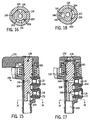
- Figs. 15-18 show a further embodiment and use like reference numerals from above where appropriate to facilitate understanding.
- the rotational stops for the opening and closing movements of the valve 200 are moved from the handle to the piston.
- piston 136 has an arcuate slot 201 with shoulders 202 and 204 at the ends thereof.
- piston 136 In the closed position of the valve, Fig. 15, piston 136 is in its clockwise rotated position, Fig. 16, with shoulder 204 stopped against radially inwardly projecting finger 206 formed on the inner cylindrical surface of housing 104.
- piston 136 In the open position of the valve, Fig. 17, piston 136 is rotated 90° counter-clockwise, Fig. 18, and shoulder 202 is stopped against finger 206.
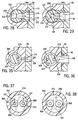
- Drain valve 218 has a housing 220 and an actuator member provided by a rotary piston 222 rotatable about a vertical axis and having an upper manually engageable operator handle 224 nonrotatably secured to piston 222 by pin 226 and biased by spring 228 to return to the closed position, Figs. 19 and 20.
- shoulder 230 of arcuate slot 232 of piston 222 is stopped against radially inwardly projecting finger 234 of the inner cylindrical surface of housing 220.
- Piston 222 is rotated 90° counter-clockwise, as viewed in Figs. 20 and 22, to the open position, Fig. 21, with shoulder 236 of arcuate slot 232 stopped against finger 234.
- a vent passage 238, Fig. 21, has a first portion 240 extending radially in piston 222, relative to the noted vertical rotational axis of piston 222, and a second portion 242 extending axially in the piston.
- First portion 240 of the vent passage extends between an upstream end 244 and a downstream end 246.
- Second portion 242 of the vent passage extends between an upstream end 248 and a downstream end 250.
- Upstream end 244 of first portion 240 is continuous with and continuously communicates with downstream end 250 of second portion 242 of the vent passage including in each of the open and closed positions of the piston.
- Downstream end 246 of first portion 240 communicates with first port 116 when the piston is in the open position, Fig. 21, and is blocked from communication with first port 116 when the piston is in the closed position, Fig. 19.
- Upstream end 248 of second portion 242 communicates with third port 120 in each of the open and closed positions of the piston.
- Drain passage 252 has a first portion 254 extending radially in piston 222, and a second portion 256 extending axially in piston 222.
- First portion 254 extends between an upstream end 258 and a downstream end 260.
- Second portion 256 of the drain passage extends between an upstream end 262 and a downstream end 264.
- Downstream end 260 of first portion 254 is continuous with and in continuous communication with upstream end 262 of second portion 256 including in each of the open and closed positions of the piston.
- Upstream end 258 of first portion 254 communicates with second port 118 when the piston is in the open position, Fig. 21, and is blocked from communication with second port 118 when the piston is in the closed position, Fig. 19.
- Downstream end 264 of second portion 256 communicates with third port 120 in each of the open and closed positions of the piston, Figs. 21 and 19, respectively.
- Drain valve 278 has a housing 280 and an actuator member provided by a rotary piston 282 rotatable about a vertical rotation axis and having an upper handle 284 nonrotatably secured to piston 282 by pin 286 and biased to a closed position by return spring 288.
- a rotary piston 282 rotatable about a vertical rotation axis and having an upper handle 284 nonrotatably secured to piston 282 by pin 286 and biased to a closed position by return spring 288.
- shoulder 290, Fig. 25 of arcuate slot 292 on the outer surface of piston 282 is stopped against radially inwardly projecting finger 294 of the inner cylindrical surface of drain valve housing 280.
- shoulder 296 of arcuate slot 292 is stopped against finger 294.
- a vent passage 298, Fig. 26, has a first portion 300 extending radially through piston 282, relative to the noted vertical rotational axis, and a second portion 302 extending axially along a gap between piston 282 and drain valve housing 280.
- First portion 300 of the vent passage extends between an upstream end 304 and a downstream end 306.
- Second portion 302 of the vent passage extends between an upstream end 308 and a downstream end 310.
- Upstream end 304 of the first portion 300 is continuous with and continuously communicates with downstream end 310 of second portion 302 of the vent passage including in each of the open and closed positions of the piston.
- Downstream end 306 of first portion 300 communicates with first port 116 when the piston is in the open position, Figs. 26, 28, and is blocked from communication with first port 116 when the piston is in the closed position, Fig. 24.
- Upstream end 308 of second portion 302 communicates with third port 120 in each of the open and closed positions of the piston.
- Drain passage 312, Fig. 26, has a first portion 314 extending radially in the piston, and a second portion 316 extending axially in the piston.
- First portion 314 extends between an upstream end 318 and a downstream end 320.
- Second portion 316 of the drain passage extends between an upstream end 322 and a downstream end 324.
- Downstream end 320 of first portion 314 is continuous with and in continuous communication with upstream end 322 of second portion 316 of the drain passage including in each of the open and closed positions of the piston.
- Upstream end 318 of first portion 314 is in communication with second port 118 when the piston is in the open position, Figs. 26, 29, and is blocked from communication with second port 118 when the piston is in the closed position, Fig. 24.
- Downstream end 324 of second portion 316 is in communication with third port 120 in each of the open and closed positions of the piston.
- Drain valve 340 includes a drain valve housing 342 and an actuator member provided by a rotary piston 344 rotatable about a vertical rotation axis and having an upper manually engageable handle 346 nonrotatably secured to piston 344 by pin 348 and biased to the closed position, Figs. 30, 34, 38, by return spring 350.
- a rotary piston 344 rotatable about a vertical rotation axis and having an upper manually engageable handle 346 nonrotatably secured to piston 344 by pin 348 and biased to the closed position, Figs. 30, 34, 38, by return spring 350.
- radially outwardly projecting finger 352, Fig. 31, on the outer surface of piston 344 is stopped against shoulder 354 of an arcuate slot 356 formed in the inner cylindrical surface of drain valve housing 342.
- Fig. 32, finger 352, Fig. 33 is stopped against shoulder 358 of arcuate slot 356.
- Drain valve 340 includes an upper cap 360, Fig. 30, thread mounted on housing 342.
- Spring 350 axially bears between cap 360 and a shoulder 362 on the piston and, in addition to the noted rotary bias, also supplies axial bias such that piston 344 is axially biased downwardly against a pair of lower O-ring seals 364 and 366, Figs. 30, 34, 37, 38.
- O-ring 364 is aligned with lower drain port 368 in lower horizontal wall 370 of housing 342.
- O-ring 366 is aligned with lower vent port 372 in horizontal wall 370.
- Ports 368 and 372 communicate with the noted third port 120 of the drain valve.
- Piston 344 is axially biased downwardly against O-rings 364 and 366 in sealing relation.
- a vent passage 374, Fig. 32 has a first portion 376 extending radially in piston 344, and a second portion 378 extending axially in the piston.
- First portion 376 extends between an upstream end 380 and a downstream end 382.
- Second portion 378 of the vent passage extends between an upstream end 386 and a downstream end 388.
- Upstream end 380 of first portion 376 is continuous with and in continuous communication with downstream end 388 of second portion 378 of the vent passage including in each of the open and closed positions of the piston.
- Downstream end 382 of first portion 376 is in communication with first port 116 in each of the open and closed positions of the piston, Figs. 32 and 30, respectively. This is accomplished by an arcuate groove 384, Figs.
- Drain passage 400 has a first portion 402 extending radially in piston 344, and a second portion 404 extending axially in piston 344.
- First portion 402 extends between an upstream end 406 and a downstream end 408.
- Second portion 404 of the drain passage extends between an upstream end 412 and a downstream end 414.
- Downstream end 408 of first portion 402 is continuous with and in continuous communication with upstream end 412 of second portion 404 of the drain passage including in each of the open and closed positions of the piston.
- Upstream end 406 of first portion 402 communicates with second port 118 in each of the open and closed positions of the piston, Figs. 32 and 30, respectively.
- vent and drain passage arcuate grooves 384 and 410 may be formed in the inner cylindrical surface of the drain valve housing.
- Downstream end 414 of second portion 404 communicates with third port 120 through O-ring 364 and drain port 368 when the piston is in the open position,, Figs. 32 and 37.
- Downstream end 414 of second portion 404 is blocked from communication with drain port 368 and third port 120 when the piston is in the closed position, Figs. 30 and 38.
- Drain valve 430 includes a drain valve housing 432 having an actuator member provided by a rotary piston 434 rotatable about a vertical rotation axis and having an upper manually engageable handle 436 nonrotatably secured to piston 434 by pin 438 and biased to the closed position, Figs. 39, 45, by return spring 440.
- a bottom end cap 442 is mounted to the housing in threaded relation to axially locate and retain the piston in the housing and to provide an axial stop for lower springs 444 and 446, Fig.
- a lower cup-shaped retainer member 456 has respective vent and drain ports 458 and 460 therethrough aligned with respective vent and drain ports 452 and 454 and the respective openings in respective annular seals 448 and 450 and the respective hollow interiors of springs 444 and 446.
- Springs 444 and 446 bear axially between retainer member 456 and respective annular seals 448 and 450.
- Retainer member 456 is held in place by lower end cap 442 and is sealed to housing 432 by O-ring 462.
- vent air 132 flows upwardly through third port 120, vent ports 458 and 452 then through portions 464 and 466, Fig. 41 of vent passage 468 to first port 116 communicating with vent opening 100.
- the collected water drain stream 130 flows from drain opening 98 to second port 118 then through portions 470 and 472 of drain passage 474 then through drain ports 454 and 460 to third port 120.
- Drain valve 500 includes a drain valve housing 502 and an actuator member provided by a rotary piston 504 rotatable about a vertical rotation axis and having an upper manually engageable handle 506 nonrotatably secured to piston 504 in keyed relation, such as square fit 508 or the like, and biased to the closed position, Fig. 47, by return spring 510.
- Vent passage 512, Fig. 49 extends from first port 116 radially at 514 in the piston then axially at 516 in the piston through lower vent port 518 through bottom wall 520 of the housing when the piston is in the open position, Figs. 49, 50.
- Vent port 518 in turn communicates with annular passage 522 around drain port 524 at third port 120.
- Axial vent passage portion 516 is blocked from communication with vent port 518 in bottom wall 520 when the piston is in the closed position, Fig. 47.
- Radial portion 514 of the vent passage is blocked from communication with first port 116 when the piston is in the closed position, Fig. 47.
- Drain passage 526 has a portion 528 extending radially from second port 118 and a portion 530 extending axially and communicating with drain port 524 and third port 120 in each of the open and closed positions of the piston, Figs. 49 and 47, respectively.
- O-rings 532 and 534 permit the noted rotation and seal the interior of the valve.
- Additional O-rings 536 and 538 are provided around respective portions 514 and 528 of respective vent and drain passages 512 and 526.
- Drain valve 550 includes a drain valve housing 552 and an actuator member provided by a reciprocal plunger 554 preferably reciprocal along a vertical reciprocation axis.
- a vent passage 556 has a first portion 558 extending from first port 116 radially in drain valve housing 552, relative to the noted reciprocation axis 560, a second portion 562 extending axially in housing 552 along plunger 554, a third portion extending radially in housing 552, a fourth portion 556 extending axially in housing 552, and a fifth portion 568 extending radially in housing 552.
- Radial portions 558 and 564 are joined by axial portion 562 when plunger 554 is in the open position, Fig. 55.
- Axial portion 566 is radially spaced from axial portion 562. Vent air 132 through the vent passage flows from third port 120 through portion 568 then axially through portion 566 then radially through portion 564 then axially through portion 562 then radially through portion 558 to first port 116 and vent opening 100.
- Housing 552 has a drain chamber 570 and a vent chamber 572 spaced from each other by a dividing wall 574. Plunger 554 reciprocates in the vent and drain chambers between open and closed positions, Figs. 55 and 54, respectively. In the open position, Fig.
- Drain passage 576 has a first portion 578 extending radially in drain valve housing 552, relative to axis 560, and a second portion 580 extending axially along plunger 554 to third port 120. O-ring seals 582,584,586 are provided along the plunger for sealing the respective passages.
- a self-biasing molded rubber or plastic cap 588 is secured to the top of the plunger and biases the plunger upwardly to the closed position, Fig. 54. To open to valve, the operator manually pushes down on cap 588 as shown at arrow 589, Fig. 55.
- a return spring 590 may be provided to bias plunger 554 upwardly to the closed position.
- Drain valve 600 includes a drain valve housing 602 having an actuator member provided by a rotary piston 604 rotatable about a vertical rotation axis and having an upper manually engageable handle 606 nonrotatably secured to piston 604 by pin 608 and biased by return spring 610, as above.
- Vent passage 612 has a first portion 614 extending radially through piston 604, relative to the noted rotation axis, and a second portion 616 extending axially through housing 602.
- the operation of drain valve 600 is like that described above except that the axial portion 616 of the vent passage extends through the drain valve housing 602 rather than extending along a gap between piston 604 and housing 602, and rather than extending through piston 604.
Landscapes
- Chemical & Material Sciences (AREA)
- Chemical Kinetics & Catalysis (AREA)
- Engineering & Computer Science (AREA)
- Physics & Mathematics (AREA)
- Thermal Sciences (AREA)
- Combustion & Propulsion (AREA)
- Mechanical Engineering (AREA)
- General Engineering & Computer Science (AREA)
- Multiple-Way Valves (AREA)
- Filtration Of Liquid (AREA)
- Self-Closing Valves And Venting Or Aerating Valves (AREA)
- Separating Particles In Gases By Inertia (AREA)
Abstract
Description
- The invention relates to fuel filter water separators for internal combustion engines, usually diesel engines, and more particularly to a drain valve therefor.
- Diesel fuel tends to contain relatively high levels of impurities such as particulate matter and water, as compared to corresponding levels in other liquid hydrocarbon fuels. As a consequence, diesel fuel typically needs to be filtered before injecting the diesel fuel into the engine. The concern over the levels of particulate matter and water in the diesel fuel are significant due to the problems which can be caused. Particulate matter can clog fuel lines and fuel injectors and cause deposits to be formed in the combustion chamber. When water-laden diesel fuel is run through a fuel system and engine, the presence of the water can cause the fuel injection system to malfunction due to rust, corrosion, deposits, etc. Excessive levels of water may lead to catastrophic injector nozzle failure due to the effects of steam expansion and/or lubricity effects.
- Fuel filter water separators are known in the prior art for filtering the particulate matter and removing the water. Fuel filter water separators with a drain valve for periodically draining the collected water are also known in the prior art, for example as shown in U.S. Patent 5,855,772, incorporated herein by reference.
- The present invention provides an improved drain valve for a fuel filter water separator. The fuel filter water separator has a housing defining a water collection space and a vent space. The housing has a wall with a drain opening therethrough for draining water from the water collection space, and a vent opening therethrough and permitting incoming air to replace outgoing water. The engine has a running condition wherein the fuel filter water separator is pressurized, and an off condition wherein the fuel filter water separator is not pressurized. The drain valve includes a housing mounted to the fuel filter water separator housing and having a first port mating with the vent opening, a second port mating with the drain opening, and a third port. An actuator member in the drain valve housing is actuatable between a closed position blocking communication of the first port with the third port and blocking communication of the second port with the third port. The actuator member in the drain valve housing is actuatable to an open position providing communication of the first port with the third port and providing communication of the second port with the third port. In a typical situation, when the operator sees an indication that water is present, he turns off the engine, thus depressurizing the fuel filter water separator, and opens the drain valve by actuating the actuator member to the open position, and collected water and vent air each flow through the noted third port, but in opposite directions, i.e., if the operator opens the drain valve during the off condition of the engine with the fuel filter water separator not pressurized, the first port draws air through the vent passage from around the drain stream of collected water flowing in the opposite direction in the third port. In one embodiment, if the actuator member of the drain valve is actuated to the open position when the engine is in the running condition and providing pressurized fuel at the noted vent opening, then fuel spray from the vent opening and collected water from the drain opening of the fuel filter water separator housing each flow through the noted third port in the same direction, i.e. if the operator opens the drain valve during the running condition of the engine with the fuel filter water separator pressurized, a pressurized fuel vent stream from the first port joins the drain stream from the second port at the third port and flows in the same direction therethrough.
- According to this invention there is provided a drain valve for a fuel filter water separator for an internal combustion engine, said fuel filter water separator having a housing defining a water collection space and a vent space, the housing having a wall with a drain opening therethrough for draining water from said water collection space, and having a vent opening therethrough and permitting incoming air to replace outgoing water, said engine having a running condition wherein said fuel filter water separator is pressurized, said engine having an off condition wherein said fuel filter water separator is not pressurized, said drain valve comprising a housing mounted to said fuel filter water separator housing and having a first port mating with said vent opening, a second port mating with said drain opening, and a third port, and an actuator member in said drain valve housing and actuable between a closed position blocking communication of said first port with said third port and blocking communication of said second port with said third port, and an open position providing communication of said first port with said third port and providing communication of said second port with said third port such that if said actuator member of said drain valve is actuated to said open position when said engine is in said off condition, collected water and vent air each flow through said third port in opposite directions.
- A preferred form of drain valve which embodies this invention may have one or more of the following features.
- The third port may be gravitationally below the drain opening.
- The drain opening may be gravitationally below the vent opening.
- The third port may be gravitationally below the second port.
- The second port may be gravitationally below the first port.
- A seal radially bearing between the drain valve housing and the piston at the first port may be provided.
- A seal axially bearing between the drain valve housing and the piston at the third port may be provided.
- The first portion of the vent passage may extend between an upstream end and a downstream end, the upstream end communicating with the second portion of the vent passage when the piston is in the open position, the downstream end communicating with the first port when the piston is in the open position, the downstream end being blocked from communication with the first port when the piston is in the closed position.
- The upstream end of the first portion of the vent passage may communicate with the second portion of the vent passage when the piston is in the closed position. There may be a drain passage having a first portion extending radially in the piston, and a second portion extending axially in the piston.
- The first portion of the drain passage may extend between an upstream end and a downstream end, the upstream end communicating with the second port when the piston is in the open position, the second portion of the drain passage extending between an upstream end and a downstream end, the upstream end of the second portion of the drain passage communicating with the downstream end of the first portion of the drain passage in each of the open and closed positions of the piston, the downstream end of the second portion of the drain passage communicating with the third port when the piston is in the open position, at least one of the upstream ends of the first portion of the drain passage and the downstream end of the second portion of the drain passage being blocked from communication with a respective one of the second and third ports when the piston is in the closed position.
- The upstream end of the first portion of the drain passage may be blocked from communication with the second port when the piston is in the closed position. The downstream end of the second portion of the drain passage may communicate with the third port in each of the open and closed positions of the piston. The downstream end of the second portion of the drain passage may be blocked from communication with the third port when the piston is in the closed position. The upstream end of the first portion of the drain passage may communicate with the second port in each of the open and closed positions of the piston. An arcuate groove in one of the piston and the drain valve housing may communicate with the upstream end of the first portion of the drain passage and the second port in each of the open and closed positions of the piston.
- When the actuator member is a rotary piston comprising a vent passage having a first portion extending radially in the piston and a second portion extending axially in the piston, the vent passage may extend between an upstream end and a downstream end, the downstream end communicating with said first port when said piston is in the open position, the second portion of the vent passage extending between an upstream end and a downstream end, the upstream end of the second portion of the vent passage communicating with the third port when the piston is in the open position, the downstream end of the second portion of the vent passage communicating with the upstream end of the first portion of the vent passage in each of the open and closed positions of the piston, at least one of the downstream end of the first portion of the vent passage and the upstream end of the second portion of the vent passage being blocked from communication with a respective one of the first and third ports when the piston is in the closed position. The upstream end of the second portion of the vent passage may be in communication with the third port in each of the open and closed positions of the piston.
- The upstream end of the second portion of the vent passage may be blocked from communication with the third port when the piston is in the closed position.
- The downstream end of the first portion of the vent passage may be in communication with the first port in each of the open and closed positions of the piston.
- An arcuate groove in one of the piston and the drain valve may communicate with the downstream end of the first portion of the vent passage and the first port in each of the open and closed positions of the pistons.
- First and third seals which bear radially between the drain valve housing and the piston at the first and second ports at the radially extending first portions of the vent passage and drain passage respectively may be provided.
- First and second seals which bear axially between the drain valve housing and the piston at the third port at the axially extending positions of the vent passage and the drain passage respectively may be provided.
- The vent passage may have a third portion extending radially in the drain valve housing and a fourth portion extending axially in the drain valve housing, the second portion extending axially along the plunger, the first and third portions being joined by the second portion, the fourth portion being radially spaced from the second portion, the vent passage may have a fifth portion extending radially in the drain valve housing, such that vent air through the vent passage flows from the third port then through the fifth portion then axially through the fourth portion then radially through the third portion then axially through the second portion then radially through the first portion to the vent opening.
- The drain valve housing may have a drain chamber and a vent chamber axially spaced from each other by a dividing wall, and the plunger may extend axially through the dividing wall and may reciprocate in the drain and vent chambers between open and closed positions, such that in the open position, collected water flows from the drain chamber along the plunger into the third port, and vent air flows in the opposite direction through the third port towards the plunger and then enters the vent passage at the fifth portion.
- A drain passage having a first portion extending radially in the drain valve housing, relative to the axis and a second portion extending axially along the plunger to the third port may be provided.
-
- Fig. 1 is like Fig. 7 of incorporated US Patent 5,855,772 but shows a drain valve which embodies the present invention;
- Fig. 2 is an exploded perspective view of the drain valve of Fig. 1;
- Fig. 3 is an assembled perspective view of the drain valve of Figs. 1 and 2;
- Fig. 4 is a sectional view taken along line 4-4 of Fig. 1, and shows the valve in the closed position.
- Fig. 5 is a sectional view taken along line 5-5 of Fig. 4;
- Fig. 6 is a sectional view taken along line 6-6 of Fig.4;
- Fig. 7 is a sectional view taken along line 7-7 of Fig.4;
- Fig. 8 is a side elevation view of the valve of Figs. 3 and 4, but shows the valve in the open position.
- Fig. 9 is a sectional view taken along line 9-9 of Fig. 8;
- Fig. 10 is a sectional view taken along line 10-10 of Fig. 9;
- Fig. 11 is a sectional view taken along line 11-11 of Fig.9;
- Fig. 12 is a sectional view taken along line 12-12 of Fig. 9;
- Fig. 13 is a sectional view taken along line 13-13 of Fig. 9;
- Fig. 14 is a sectional view taken along line 14-14 of Fig. 10;
- Fig. 15 is a sectional view of another embodiment of a drain valve in accordance with the invention.
- Fig. 16 is a sectional view taken along line 16-16 of Fig. 15.
- Fig. 17 is a sectional view showing the valve of Fig. 15 in the open position.
- Fig. 18 is a sectional view taken along line 18-18 of Fig. 17.
- Fig. 19 is a sectional view of another embodiment of a drain valve in accordance with the invention.
- Fig. 20 is a sectional view taken along line 20-20 of Fig. 19.
- Fig. 21 is a sectional view showing the valve of Fig. 19 in the open position.
- Fig. 22 is a sectional view taken along line 22-22 of Fig. 21.
- Fig. 23 is a bottom end elevation view taken along line 23-23 of Fig. 21.
- Fig. 24 is a sectional view of another embodiment of a drain valve in accordance with the invention.
- Fig. 25 is a sectional view taken along line 25-25 of Fig. 24.
- Fig. 26 is a sectional view showing the valve of Fig. 24 in the open position.
- Fig. 27 is a sectional view taken along line 27-27 of Fig. 26.
- Fig. 28 is a sectional view taken along line 28-28 of Fig. 26.
- Fig. 29 is a sectional view taken along line 29-29 of Fig. 26.
- Fig. 30 is a sectional view showing another embodiment of a drain valve in accordance with the invention.
- Fig. 31 is a sectional view taken along line 31-31 of Fig. 30.
- Fig. 32 is a sectional view showing the drain valve of Fig. 30 in the open position.
- Fig. 33 is a sectional view taken along line 33-33 of Fig. 32.
- Fig. 34 is an enlarged view of a portion of Fig. 30 as shown at line 34-34 in Fig. 30.
- Fig. 35 is a sectional view taken along line 35-35 of Fig. 32.
- Fig. 36 is a sectional view taken along line 36-36 of Fig. 32.
- Fig. 37 is a sectional view taken along line 37-37 of Fig. 32.
- Fig. 38 is a sectional view taken along line 38-38 of Fig. 30.
- Fig. 39 is a sectional view showing another embodiment of a drain valve in accordance with the invention.
- Fig. 40 is a sectional view taken along line 40-40 of Fig. 39.
- Fig. 41 is a sectional view showing the drain valve of Fig. 39 in the open position.
- Fig. 42 is a sectional view taken along line 42-42 of Fig. 41.
- Fig. 43 is an enlarged view of a portion of Fig. 41.
- Fig. 44 is a sectional view taken along line 44-44 of Fig. 41.
- Fig. 45 is a sectional view taken along line 45-45 of Fig. 39.
- Fig. 46 is a top view of another embodiment of a drain valve in accordance with the invention.
- Fig. 47 is a sectional view taken along line 47-47 of Fig. 46.
- Fig. 48 is a top view showing the drain valve of Fig. 46 in the open position.
- Fig. 49 is a sectional view taken along line 49-49 of Fig. 48.
- Fig. 50 is a sectional view taken along line 50-50 of Fig. 49.
- Fig. 51 is a sectional view taken along line 51-51 of Fig. 49.
- Fig. 52 is an enlarged view of a portion of Fig. 49.
- Fig. 53 is a sectional view taken along line 53-53 of Fig. 52.
- Fig. 54 is a sectional view of another embodiment of a drain valve in accordance with the invention.
- Fig. 55 is a sectional view showing the drain valve of Fig. 54 in the open position.
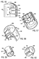
- Fig. 56 is a side elevation view partially cut away of a further embodiment of the drain valve of Fig. 54.
- Fig. 57 is a perspective view from below, partially cut away, of the drain valve of Fig. 56.
- Fig. 58 is a perspective view from above, partially cut away, of the drain valve of Fig. 56.
- Fig. 59 is a perspective view from below of the drain valve of Fig. 56.
- Fig. 60 is a perspective view from above of the drain valve of Fig. 56.
- Fig. 61 is a sectional view of another embodiment of a drain valve in accordance with the invention.
-
- Fig. 1 shows a fuel
filter water separator 70 and will be only briefly described since it is also shown at 20 in incorporated U.S. Patent 5,855,772 to which further reference may be had. Fuelfilter water separator 70 includes ahousing 72 closed by a threadedlid 74 and having a filter andwater separating element 76 therein. Diesel fuel enters atfuel inlet 78, flows radially inwardly throughannular filter element 76 to hollow interior 80 and then flows throughfuel outlet 82 to the fuel injection system ofinternal combustion engine 84, such as a diesel engine. The housing includes aheater ring 86 for heating the diesel fuel to prevent it from coalescing in cold weather, a heater connector/thermostat assembly 88, and a water-in-fuel (WIF)sensor 90, all as is known in the prior art and as shown in the incorporated '772 patent.Housing 72 defines awater collection space 92 and avent space 94. The housing has awall 96 with adrain opening 98 therethrough for draining water from the water collection space. The wall has avent opening 100 therethrough and permitting incoming air to replace outgoing water. The engine has a running condition wherein the fuel system including the fuel filter water separator is pressurized, and an off condition wherein the fuel system and fuel filter water separator is not pressurized. As is known, it is typical to drain collected water fromhousing 72 with the engine in the off condition. This is done by allowing collected water to flow throughdrain opening 98, and allowing incoming vent air to flow through vent opening 100 to replace the outgoing water and allow flow thereof. In the noted pressurized condition, fuel pressure in the fuel filter water separator provides pressurized fuel atvent opening 100, such that if the control valve therefor is opened during the running condition of the engine, pressurized fuel sprays outwardly throughvent opening 100. -
Drain valve 102 includes ahousing 104, Fig. 2, mounted to fuel filterwater separator housing 72 bybolts thickness section 114 of the fuel filter water separator housing wall. The drain valve housing has afirst port 116, Figs. 9 and 12 mating withvent opening 100. The drain valve housing has asecond port 118, Figs. 9 and 13, mating withdrain opening 98. The drain valve housing has athird port 120, Figs. 1 and 9, at the bottom thereof which is a combined vent and drain port and to which adrain hose 122, Figs. 2 and 3, may be connected at outer barbs 124 and retained byclamp 126. - An
actuator member 128 indrain valve housing 104 is actuatable between a closed position, Figs. 1-7, and an open position, Figs. 8-14. The closed position blocks communication offirst port 116 withthird port 120 and blocks communication ofsecond port 118 withthird port 120. The open position provides communication offirst port 116 withthird port 120 and provides communication ofsecond port 118 withthird port 120. Ifactuator member 128 ofdrain valve 102 is actuated to the open position when the engine is in the noted off condition, collected water and vent air each flow throughthird port 120, but in opposite directions, Fig. 9, as shown atdrain stream 130 and ventair stream 132.First port 116 draws air through the vent passage, to be described, from arounddrain stream 130 of collected water flowing in the opposite direction inthird port 120. - If
actuator member 128 ofdrain valve 102 is actuated to the open position when the engine is in the noted running condition, pressurized fuel spray from vent opening 100 and collected water fromdrain opening 98 of the fuel filter water separator housing each flow throughthird port 120 in the same direction as shown as fuelspray phantom arrow 134 and drainarrow 130, Fig. 9. In such instance, a pressurizedfuel vent stream 134 fromfirst port 116 joinsdrain stream 130 fromsecond port 118 atthird port 120, and streams 134 and 130 flow in the same direction throughport 120 to exit same, preferably throughdrain hose 122, Fig. 3. - The drain valve has preferred vertical or gravitational orientation of the ports, particularly desirable for the noted non-pressurized drain cycle, i.e. with the engine in the noted off condition.
Third port 120 is gravitationally belowsecond port 118 which in turn is gravitationally belowfirst port 116.Third port 120 is gravitationally belowdrain opening 98 which in turn is gravitationally belowvent opening 100. - In Fig. 2,
actuator member 128 is arotary piston 136 rotatable about avertical axis 138. Avent passage 140, Figs. 2, 4, 9, 12, has afirst portion 142, Figs. 4, 9, 12, extending radially throughpiston 136, relative toaxis 138, and asecond portion 144, Figs. 4, 9, 11, extending axially along a gap betweenpiston 136 and drainvalve housing 104. In the open position of the valve, Fig. 9, such gap is between aflat surface 146, Figs. 11,12, on the outer surface of the piston, and a notchedsurface 148 on the inner cylindrical surface of the drain valve housing.First portion 142 ofvent passage 140 extends between anupstream end 150 and adownstream end 152, Figs. 9 and 12.Second portion 144 ofvent passage 140 extends between anupstream end 143, Fig. 9, and adownstream end 145.Downstream end 145 ofsecond portion 144 is continuous with and in continuous communication withupstream end 150 offirst portion 142, including in both of the noted open and closed positions.Downstream end 152 offirst portion 142 communicates withfirst port 116 whenpiston 136 is in the noted open position, as shown in Figs. 9 and 12.Downstream end 152 is blocked from communication withfirst port 116 whenpiston 136 is in the noted closed position, Fig. 4. Anannular sealing grommet 154, Figs. 2, 9, 12, radially bears betweendrain valve housing 104 andpiston 136 atfirst port 116.Piston 136 is preferably formed with aball socket portion 156, Fig. 2, atvent port 140 to facilitate engagement with sealinggrommet 154 and rotation ofpiston 136 while maintaining the seal.Upstream end 143 ofsecond portion 144 of the vent passage is in communication withthird port 120 in each of the open and closed positions of the piston. - A
drain passage 158, Figs. 2, 4, 9, 13, has afirst portion 160, Figs. 4, 9, 13, extending radially inpiston 136, relative toaxis 138, and asecond portion 162 extending axially inpiston 136.First portion 160 extends between anupstream end 164 and adownstream end 166.Second portion 162 extends between anupstream end 168 and adownstream end 170.Upstream end 168 ofsecond portion 162 is continuous with and in continuous communication withdownstream end 166 offirst potion 160 including in each of the noted open and closed positions of the piston.Downstream end 170 ofsecond portion 162 is in communication withthird port 120 in each of the open and closed positions of the piston.Upstream end 164 offirst portion 160 is in communication withsecond port 118 whenpiston 136 is in the open position as shown in Figs. 9 and 13.Upstream end 164 is blocked from communication withsecond port 118 whenpiston 136 is in the closed position, as shown in Figs. 4 and 7. Anannular sealing grommet 172, Figs. 2, 7, 9, 13, radially bears betweendrain valve housing 104 andpiston 136 atsecond port 118.Piston 136 is provided with a secondball socket portion 174, Fig. 2, arounddrain passage 158 to facilitate and maintain the seal against sealinggrommet 172 and to maintain such seal during rotation ofpiston 136. -
Drain valve 102 includes an manually engageableupper handle 176, Figs. 1 and 2, non-rotatably secured topiston 136 byroll pin 178.Coil spring 180 is a return spring and biases the valve handle to return to the closed position, Figs. 1-7, when released by the operator.Ball sockets piston 136 in cooperation withgrommets piston 136 inhousing 104 and retain the piston in the housing. Additional retention is preferably provided bypin 182, Figs. 8, 14, engaging the underside ofhousing lip 184, Figs. 2, 14. In the closed position of the valve, Fig. 5, edge 184 of the handle is stopped againstshoulder 186 ofhousing 104. When the valve is actuated to the open position, handle 176 is manually rotated by theoperator 90° counter-clockwise to the position shown in Fig. 10, withhandle edge 188 stopped againstshoulder 190 ofhousing 104. O-ring 192, Figs. 4, 9, permits the noted rotation while sealing the interior of the valve. - Figs. 15-18 show a further embodiment and use like reference numerals from above where appropriate to facilitate understanding. The rotational stops for the opening and closing movements of the
valve 200 are moved from the handle to the piston. As shown in Figs. 16 and 18,piston 136 has anarcuate slot 201 withshoulders piston 136 is in its clockwise rotated position, Fig. 16, withshoulder 204 stopped against radially inwardly projectingfinger 206 formed on the inner cylindrical surface ofhousing 104. In the open position of the valve, Fig. 17,piston 136 is rotated 90° counter-clockwise, Fig. 18, andshoulder 202 is stopped againstfinger 206. - Figs. 19-23 show a further embodiment and use like reference numerals from above where appropriate to facilitate understanding.
Drain valve 218 has ahousing 220 and an actuator member provided by arotary piston 222 rotatable about a vertical axis and having an upper manually engageable operator handle 224 nonrotatably secured topiston 222 bypin 226 and biased byspring 228 to return to the closed position, Figs. 19 and 20. In Fig. 20,shoulder 230 ofarcuate slot 232 ofpiston 222 is stopped against radially inwardly projectingfinger 234 of the inner cylindrical surface ofhousing 220.Piston 222 is rotated 90° counter-clockwise, as viewed in Figs. 20 and 22, to the open position, Fig. 21, withshoulder 236 ofarcuate slot 232 stopped againstfinger 234. - A vent passage 238, Fig. 21, has a
first portion 240 extending radially inpiston 222, relative to the noted vertical rotational axis ofpiston 222, and asecond portion 242 extending axially in the piston.First portion 240 of the vent passage extends between an upstream end 244 and adownstream end 246.Second portion 242 of the vent passage extends between anupstream end 248 and adownstream end 250. Upstream end 244 offirst portion 240 is continuous with and continuously communicates withdownstream end 250 ofsecond portion 242 of the vent passage including in each of the open and closed positions of the piston.Downstream end 246 offirst portion 240 communicates withfirst port 116 when the piston is in the open position, Fig. 21, and is blocked from communication withfirst port 116 when the piston is in the closed position, Fig. 19.Upstream end 248 ofsecond portion 242 communicates withthird port 120 in each of the open and closed positions of the piston. -
Drain passage 252, Fig. 21, has afirst portion 254 extending radially inpiston 222, and asecond portion 256 extending axially inpiston 222.First portion 254 extends between anupstream end 258 and adownstream end 260.Second portion 256 of the drain passage extends between anupstream end 262 and adownstream end 264.Downstream end 260 offirst portion 254 is continuous with and in continuous communication withupstream end 262 ofsecond portion 256 including in each of the open and closed positions of the piston.Upstream end 258 offirst portion 254 communicates withsecond port 118 when the piston is in the open position, Fig. 21, and is blocked from communication withsecond port 118 when the piston is in the closed position, Fig. 19.Downstream end 264 ofsecond portion 256 communicates withthird port 120 in each of the open and closed positions of the piston, Figs. 21 and 19, respectively. - Figs. 24-29 show a further embodiment and use like reference numerals from above where appropriate to facilitate understanding.
Drain valve 278 has ahousing 280 and an actuator member provided by arotary piston 282 rotatable about a vertical rotation axis and having anupper handle 284 nonrotatably secured topiston 282 bypin 286 and biased to a closed position byreturn spring 288. In the closed position, Fig. 24,shoulder 290, Fig. 25, ofarcuate slot 292 on the outer surface ofpiston 282 is stopped against radially inwardly projectingfinger 294 of the inner cylindrical surface ofdrain valve housing 280. Upon rotation of thepiston 90° counter-clockwise, as viewed in Figs. 25 and 27, to the open position, Fig. 26,shoulder 296 ofarcuate slot 292 is stopped againstfinger 294. - A
vent passage 298, Fig. 26, has afirst portion 300 extending radially throughpiston 282, relative to the noted vertical rotational axis, and asecond portion 302 extending axially along a gap betweenpiston 282 and drainvalve housing 280.First portion 300 of the vent passage extends between anupstream end 304 and adownstream end 306.Second portion 302 of the vent passage extends between anupstream end 308 and adownstream end 310.Upstream end 304 of thefirst portion 300 is continuous with and continuously communicates withdownstream end 310 ofsecond portion 302 of the vent passage including in each of the open and closed positions of the piston.Downstream end 306 offirst portion 300 communicates withfirst port 116 when the piston is in the open position, Figs. 26, 28, and is blocked from communication withfirst port 116 when the piston is in the closed position, Fig. 24.Upstream end 308 ofsecond portion 302 communicates withthird port 120 in each of the open and closed positions of the piston. -
Drain passage 312, Fig. 26, has afirst portion 314 extending radially in the piston, and asecond portion 316 extending axially in the piston.First portion 314 extends between anupstream end 318 and adownstream end 320.Second portion 316 of the drain passage extends between anupstream end 322 and adownstream end 324.Downstream end 320 offirst portion 314 is continuous with and in continuous communication withupstream end 322 ofsecond portion 316 of the drain passage including in each of the open and closed positions of the piston.Upstream end 318 offirst portion 314 is in communication withsecond port 118 when the piston is in the open position, Figs. 26, 29, and is blocked from communication withsecond port 118 when the piston is in the closed position, Fig. 24.Downstream end 324 ofsecond portion 316 is in communication withthird port 120 in each of the open and closed positions of the piston. - Figs. 30-38 show a further embodiment and use like reference numerals from above where appropriate to facilitate understanding.
Drain valve 340 includes adrain valve housing 342 and an actuator member provided by arotary piston 344 rotatable about a vertical rotation axis and having an upper manuallyengageable handle 346 nonrotatably secured topiston 344 bypin 348 and biased to the closed position, Figs. 30, 34, 38, byreturn spring 350. In the closed position, radially outwardly projectingfinger 352, Fig. 31, on the outer surface ofpiston 344 is stopped againstshoulder 354 of anarcuate slot 356 formed in the inner cylindrical surface ofdrain valve housing 342. Upon 90° clockwise rotation of the piston, as viewed in Figs. 31 and 33, to the open position, Fig. 32,finger 352, Fig. 33, is stopped againstshoulder 358 ofarcuate slot 356. -
Drain valve 340 includes anupper cap 360, Fig. 30, thread mounted onhousing 342.Spring 350 axially bears betweencap 360 and ashoulder 362 on the piston and, in addition to the noted rotary bias, also supplies axial bias such thatpiston 344 is axially biased downwardly against a pair of lower O-ring seals ring 364 is aligned withlower drain port 368 in lowerhorizontal wall 370 ofhousing 342. O-ring 366 is aligned withlower vent port 372 inhorizontal wall 370.Ports third port 120 of the drain valve.Piston 344 is axially biased downwardly against O-rings - A
vent passage 374, Fig. 32, has afirst portion 376 extending radially inpiston 344, and asecond portion 378 extending axially in the piston.First portion 376 extends between anupstream end 380 and adownstream end 382.Second portion 378 of the vent passage extends between anupstream end 386 and adownstream end 388.Upstream end 380 offirst portion 376 is continuous with and in continuous communication withdownstream end 388 ofsecond portion 378 of the vent passage including in each of the open and closed positions of the piston.Downstream end 382 offirst portion 376 is in communication withfirst port 116 in each of the open and closed positions of the piston, Figs. 32 and 30, respectively. This is accomplished by anarcuate groove 384, Figs. 30,32, 35, formed in the outer cylindrical surface ofpiston 344 communicating withdownstream end 382 offirst portion 376 ofvent passage 374 andfirst port 116.Upstream end 386 ofsecond portion 378 is in communication withthird port 120 through O-ring 366 and ventport 372 when the piston is in the open position, Figs. 32, 35, 37.Upstream end 386 is blocked from communication withvent port 372 andthird port 120 when the piston is in the closed position, Figs. 30, 38. -
Drain passage 400, Fig. 32, has afirst portion 402 extending radially inpiston 344, and asecond portion 404 extending axially inpiston 344.First portion 402 extends between anupstream end 406 and adownstream end 408.Second portion 404 of the drain passage extends between anupstream end 412 and adownstream end 414.Downstream end 408 offirst portion 402 is continuous with and in continuous communication withupstream end 412 ofsecond portion 404 of the drain passage including in each of the open and closed positions of the piston.Upstream end 406 offirst portion 402 communicates withsecond port 118 in each of the open and closed positions of the piston, Figs. 32 and 30, respectively. This is accomplished by anarcuate groove 410 formed in the outer cylindrical surface ofpiston 344 communicating withupstream end 406 offirst portion 402 ofdrain passage 400 andsecond port 118 in each of the open and closed positions of the piston. In an alternative, either or both of vent and drain passagearcuate grooves Downstream end 414 ofsecond portion 404 communicates withthird port 120 through O-ring 364 and drainport 368 when the piston is in the open position,, Figs. 32 and 37.Downstream end 414 ofsecond portion 404 is blocked from communication withdrain port 368 andthird port 120 when the piston is in the closed position, Figs. 30 and 38. - Figs. 39-45 show a further embodiment and use like reference numerals from above where appropriate to facilitate understanding.
Drain valve 430, Fig. 39, includes adrain valve housing 432 having an actuator member provided by arotary piston 434 rotatable about a vertical rotation axis and having an upper manuallyengageable handle 436 nonrotatably secured topiston 434 bypin 438 and biased to the closed position, Figs. 39, 45, byreturn spring 440. Abottom end cap 442 is mounted to the housing in threaded relation to axially locate and retain the piston in the housing and to provide an axial stop forlower springs grommets ports retainer member 456 has respective vent and drainports ports annular seals springs Springs retainer member 456 and respectiveannular seals Retainer member 456 is held in place bylower end cap 442 and is sealed tohousing 432 by O-ring 462. - In the open position of
drain valve 430, Figs. 41, 43, 44,vent air 132 flows upwardly throughthird port 120, ventports portions vent passage 468 tofirst port 116 communicating withvent opening 100. The collectedwater drain stream 130 flows fromdrain opening 98 tosecond port 118 then throughportions drain passage 474 then throughdrain ports third port 120. - Figs. 46-51 show a further embodiment and use like reference numeral from above where appropriate to facilitate understanding.
Drain valve 500 includes adrain valve housing 502 and an actuator member provided by arotary piston 504 rotatable about a vertical rotation axis and having an upper manuallyengageable handle 506 nonrotatably secured topiston 504 in keyed relation, such assquare fit 508 or the like, and biased to the closed position, Fig. 47, byreturn spring 510.Vent passage 512, Fig. 49, extends fromfirst port 116 radially at 514 in the piston then axially at 516 in the piston throughlower vent port 518 throughbottom wall 520 of the housing when the piston is in the open position, Figs. 49, 50.Vent port 518 in turn communicates withannular passage 522 arounddrain port 524 atthird port 120. Axialvent passage portion 516 is blocked from communication withvent port 518 inbottom wall 520 when the piston is in the closed position, Fig. 47.Radial portion 514 of the vent passage is blocked from communication withfirst port 116 when the piston is in the closed position, Fig. 47.Drain passage 526 has aportion 528 extending radially fromsecond port 118 and aportion 530 extending axially and communicating withdrain port 524 andthird port 120 in each of the open and closed positions of the piston, Figs. 49 and 47, respectively. O-rings rings respective portions passages - Figs. 54-60 show a further embodiment and use like reference numerals from above where appropriate to facilitate understanding.
Drain valve 550 includes adrain valve housing 552 and an actuator member provided by areciprocal plunger 554 preferably reciprocal along a vertical reciprocation axis. Avent passage 556 has a first portion 558 extending fromfirst port 116 radially indrain valve housing 552, relative to thenoted reciprocation axis 560, a second portion 562 extending axially inhousing 552 alongplunger 554, a third portion extending radially inhousing 552, afourth portion 556 extending axially inhousing 552, and afifth portion 568 extending radially inhousing 552.Radial portions 558 and 564 are joined by axial portion 562 whenplunger 554 is in the open position, Fig. 55.Axial portion 566 is radially spaced from axial portion 562.Vent air 132 through the vent passage flows fromthird port 120 throughportion 568 then axially throughportion 566 then radially throughportion 564 then axially through portion 562 then radially through portion 558 tofirst port 116 and ventopening 100.Housing 552 has adrain chamber 570 and avent chamber 572 spaced from each other by a dividingwall 574.Plunger 554 reciprocates in the vent and drain chambers between open and closed positions, Figs. 55 and 54, respectively. In the open position, Fig. 55, collectedwater 130 flows fromdrain chamber 570 alongplunger 554 intothird port 120, and ventair 132 flows in the opposite direction throughthird port 120 towardplunger 554 and then enters the vent passage atportion 568.Drain passage 576 has afirst portion 578 extending radially indrain valve housing 552, relative toaxis 560, and asecond portion 580 extending axially alongplunger 554 tothird port 120. O-ring seals 582,584,586 are provided along the plunger for sealing the respective passages. A self-biasing molded rubber orplastic cap 588 is secured to the top of the plunger and biases the plunger upwardly to the closed position, Fig. 54. To open to valve, the operator manually pushes down oncap 588 as shown atarrow 589, Fig. 55. Alternatively, or in addition, areturn spring 590 may be provided tobias plunger 554 upwardly to the closed position. - Fig. 61 shows a further embodiment and uses like reference numerals from above where appropriate to facilitate understanding.
Drain valve 600 includes adrain valve housing 602 having an actuator member provided by arotary piston 604 rotatable about a vertical rotation axis and having an upper manuallyengageable handle 606 nonrotatably secured topiston 604 bypin 608 and biased byreturn spring 610, as above.Vent passage 612 has afirst portion 614 extending radially throughpiston 604, relative to the noted rotation axis, and asecond portion 616 extending axially throughhousing 602. The operation ofdrain valve 600 is like that described above except that theaxial portion 616 of the vent passage extends through thedrain valve housing 602 rather than extending along a gap betweenpiston 604 andhousing 602, and rather than extending throughpiston 604. - It is recognized that various equivalents, alternatives and modifications are possible within the scope of the appended claims.
Claims (10)
- A drain valve for a fuel filter water separator for an internal combustion engine, said fuel filter water separator having a housing defining a water collection space and a vent space, the housing having a wall with a drain opening therethrough for draining water from said water collection space, and having a vent opening therethrough and permitting incoming air to replace outgoing water, said engine having a running condition wherein said fuel filter water separator is pressurized, said engine having an off condition wherein said fuel filter water separator is not pressurized, said drain valve comprising a housing mounted to said fuel filter water separator housing and having a first port mating with said vent opening, a second port mating with said drain opening, and a third port, and an actuator member in said drain valve housing and actuable between a closed position blocking communication of said first port with said third port and blocking communication of said second port with said third port, and an open position providing communication of said first port with said third port and providing communication of said second port with said third port such that if said actuator member of said drain valve is actuated to said open position when said engine is in said off condition, collected water and vent air each flow through said third port in opposite directions.
- The invention according to claim 1 comprising a vent passage through said actuator member or extending along a gap between said actuator member and said drain valve housing or extending through said drain valve housing and communicating with each of said first and third ports when said actuator member is in said open position, and blocked from communication with at least of one of said first and third ports when said actuator member is in said closed position.
- The invention according to claim 1 wherein said actuator member is a rotary piston rotatable about an axis, and comprising a vent passage having a first portion extending radially in or through said piston, relative to said axis, and a second portion extending axially in said piston or along a gap between said piston and said drain valve housing.
- The invention according to claim 1 wherein said actuator member is a rotary piston rotatable about an axis, and comprising a drain passage having a first portion extending radially in said piston, relative to said axis, and a second portion extending axially in said piston.
- The invention according to claim 1 wherein said actuator member is a rotary piston rotatable about an axis and having a vent passage with a first portion extending radially, relative to said axis, and a second portion extending axially, and having a drain passage with a first portion extending radially, relative to said axis, and a second portion extending axially.
- The invention according to claim 1 wherein said actuator member is a reciprocal plunger reciprocal along an axis, and comprising a vent passage having a first portion extending radially in said drain valve housing, relative to said axis, and a second portion extending axially in said drain valve housing.
- A drain valve for a fuel filter water separator for an internal combustion engine, said fuel filter water separator having a housing defining a water collection space and a vent space, the housing having a wall with a drain opening therethrough for draining water from said water collection space, and having a vent opening therethrough and permitting incoming air to replace outgoing water, said engine having a running condition wherein said fuel filter water separator is pressurized, said engine having an off condition wherein said fuel filter water separator is not pressurized, said drain valve comprising a housing mounted to said fuel filter water separator housing and having a first port mating with said vent opening, a second port mating with said drain opening, and a third port, and an actuator member in said drain valve housing and actuable between a closed position blocking communication of said first port with said third port and blocking communication of said second port with said third port, and an open position providing communication of said first port with said third port and providing communication of said second port with said third port, and such that if said actuator member of said drain valve is actuated to said open position when said engine is in said off condition, collected water and vent air each flow through said third port in opposite directions, said drain valve having a drain passage communicating between said second and third ports at upstream and downstream ends, respectively, said drain valve having a vent passage communicating between said third and first ports at upstream and downstream ends, respectively, said vent passage having an inlet at said upstream end of said vent passage, said drain passage having an outlet at said downstream end of said drain passage, said vent passage inlet being in the same port, namely said third port, as said drain passage outlet.
- The invention according to claim 1 or claim 7 wherein fuel pressure in said fuel filter water separator during said running condition of said engine provides pressurized fuel at said vent opening, such that if said actuator member of said drain valve is actuated to said open position when said engine is in said running condition, pressurized fuel spray from said vent opening and collected water from said drain opening of said fuel filter water separator housing each flow through said third port in the same direction.
- The invention according to claim 7 wherein during said off condition of said engine with said fuel filter water separator not pressurized, said first port draws air from said vent passage from the side of the drain stream of said collected water flowing in the opposite direction in said third port.
- The invention according to claim 8 wherein during said off condition of said engine with said fuel filter water separator not pressurized, said first port draws air through said vent passage from around the drain stream of said collected water flowing in the opposite direction in said third port, and such that if said drain valve is actuated to said open position during said running condition of said engine with said fuel filter water separator pressurized, a pressurized fuel vent stream from said first port joins said drain stream from said second port at said third port and flows through said third port in the same direction as said drain stream.
Applications Claiming Priority (2)
| Application Number | Priority Date | Filing Date | Title |
|---|---|---|---|
| US09/412,713 US6358416B1 (en) | 1999-10-05 | 1999-10-05 | Drain valve for fuel filter water separator |
| US412713 | 1999-10-05 |
Publications (2)
| Publication Number | Publication Date |
|---|---|
| EP1090667A1 true EP1090667A1 (en) | 2001-04-11 |
| EP1090667B1 EP1090667B1 (en) | 2007-03-07 |
Family
ID=23634152
Family Applications (1)
| Application Number | Title | Priority Date | Filing Date |
|---|---|---|---|
| EP20000308733 Expired - Lifetime EP1090667B1 (en) | 1999-10-05 | 2000-10-04 | Drain valve for fuel filter water separator |
Country Status (6)
| Country | Link |
|---|---|
| US (2) | US6358416B1 (en) |
| EP (1) | EP1090667B1 (en) |
| JP (1) | JP2001140723A (en) |
| AU (1) | AU768580B2 (en) |
| BR (1) | BR0004328A (en) |
| DE (1) | DE60033754T2 (en) |
Cited By (2)
| Publication number | Priority date | Publication date | Assignee | Title |
|---|---|---|---|---|
| EP1172550A3 (en) * | 2000-07-10 | 2003-02-26 | Fleetguard, Inc. | A water drain valve |
| US6565746B1 (en) * | 2002-04-30 | 2003-05-20 | Dana Corporation | One-piece self-venting drain valve |
Families Citing this family (30)
| Publication number | Priority date | Publication date | Assignee | Title |
|---|---|---|---|---|
| US6358416B1 (en) * | 1999-10-05 | 2002-03-19 | Fleetguard, Inc. | Drain valve for fuel filter water separator |
| US6430842B1 (en) * | 2001-05-09 | 2002-08-13 | Carter Day International, Inc. | Assembly for supporting a rotating structure |
| JP3804949B2 (en) * | 2002-11-12 | 2006-08-02 | トヨタ紡織株式会社 | Fluid filter and drain mechanism thereof, drain jig used in fluid filter, and fluid filter drain method |
| WO2005094425A2 (en) * | 2004-03-02 | 2005-10-13 | Ds Smith Plastics Limited | Air vented liquid valve |
| US20070034580A1 (en) * | 2005-08-11 | 2007-02-15 | Stein Matthew L | Fluid filter arrangement including valve arrangement and methods |
| US7717092B2 (en) * | 2006-08-14 | 2010-05-18 | Cummins Filtration Ip Inc. | Fuel system with air venting and fuel anti-drainback |
| US8272252B2 (en) * | 2006-10-10 | 2012-09-25 | Porous Materials, Inc. | Pore structure characterization of filtration cartridges at specific locations along cartridge length |
| US7614279B2 (en) * | 2006-10-10 | 2009-11-10 | Porous Materials, Inc. | Determination of pore structure characteristics of filtration cartridges as a function of cartridge length |
| JP4784551B2 (en) * | 2007-05-09 | 2011-10-05 | トヨタ紡織株式会社 | Fluid filter |
| US8496816B2 (en) * | 2007-09-24 | 2013-07-30 | Cummins Filtration Ip, Inc. | Modular fuel filter assembly |
| CN105545551B (en) * | 2008-09-24 | 2018-09-21 | 康明斯过滤Ip公司 | Fluid sensor module and filter assemblies for filter assemblies |
| US8360251B2 (en) | 2008-10-08 | 2013-01-29 | Cummins Filtration Ip, Inc. | Multi-layer coalescing media having a high porosity interior layer and uses thereof |
| US7770526B2 (en) * | 2008-11-03 | 2010-08-10 | Draco Spring Mfg. Co., Inc | Railcar man-way cover lift-assist system |
| US20100133205A1 (en) * | 2008-12-03 | 2010-06-03 | International Truck Intellectual Property Company, Llc | Remote Actuator for a Fuel Water Separator on a Vehicle |
| US9332969B2 (en) | 2009-01-06 | 2016-05-10 | Carefusion 207, Inc. | Fluid flow control apparatus and patient fluid sampling method |
| WO2010132785A2 (en) * | 2009-05-15 | 2010-11-18 | Cummins Filtration Ip, Inc. | Surface coalescer |
| WO2011041539A1 (en) * | 2009-09-30 | 2011-04-07 | Cummins Filtration Ip Inc. | Auxiliary o-ring gland |
| US10058808B2 (en) | 2012-10-22 | 2018-08-28 | Cummins Filtration Ip, Inc. | Composite filter media utilizing bicomponent fibers |
| US9527016B2 (en) | 2014-01-24 | 2016-12-27 | Caterpillar Inc. | Filter element having vent tube and filter assembly |
| DE112015004403T5 (en) * | 2014-09-26 | 2017-06-14 | Cummins Filtration Ip, Inc. | AUTOMATIC EXHAUST SYSTEM FOR VACUUM FUEL WATER SEPARATOR |
| DE102014114486B4 (en) * | 2014-10-07 | 2021-01-28 | Norma Germany Gmbh | Drain connection |
| BR112017021385B1 (en) * | 2015-04-09 | 2022-05-03 | Parker-Hannifin Corporation | System and method for removing accumulated water from a filter and filter cartridge assembly |
| CN107921336B (en) | 2015-08-31 | 2021-04-06 | 康明斯过滤Ip公司 | filter port seal |
| DE102016005271B4 (en) | 2016-04-29 | 2019-10-02 | Mann+Hummel Gmbh | Drain control device for a filter system and filter system with a drain control device |
| DE102016005270B4 (en) | 2016-04-29 | 2019-09-05 | Mann+Hummel Gmbh | Drain control device for a filter system and filter system with a drain control device |
| CN109475790A (en) | 2016-07-19 | 2019-03-15 | 康明斯滤清系统知识产权公司 | perforated layer coalescer |
| US10344883B2 (en) * | 2016-11-02 | 2019-07-09 | Schaeffler Technologies AG & Co. KG | Modular electro-mechanical rotary valve |
| US11420141B2 (en) | 2017-08-18 | 2022-08-23 | Cummins Filtration Ip, Inc. | Fuel filter cartridge with keyed profile |
| KR102335988B1 (en) * | 2017-11-29 | 2021-12-07 | 현대자동차주식회사 | Apparatus and method for draining water and urea in fuel filter |
| DE112021001295T5 (en) * | 2020-02-28 | 2023-03-02 | Cummins Filtration Inc | NON-VENTED, SEMI-AUTOMATIC WATER DRAIN VALVE SYSTEM |
Citations (4)
| Publication number | Priority date | Publication date | Assignee | Title |
|---|---|---|---|---|
| US4611627A (en) * | 1985-02-07 | 1986-09-16 | Donaldson Company, Inc. | Self-venting drain valve |
| US4976285A (en) * | 1990-05-30 | 1990-12-11 | Parker Hannifin Corporation | Universal self-venting drain valve |
| EP0553919A1 (en) * | 1992-01-31 | 1993-08-04 | Baldwin Filters, Inc. | Self-venting drain valve |
| US5855772A (en) * | 1996-11-01 | 1999-01-05 | Fleetguard, Inc. | Fuel filter and water separator apparatus with heater |
Family Cites Families (36)
| Publication number | Priority date | Publication date | Assignee | Title |
|---|---|---|---|---|
| US410448A (en) | 1889-09-03 | Drip-cock for locomotive-cylinders | ||
| US253405A (en) | 1882-02-07 | Steam-cylinder cock | ||
| US807285A (en) | 1904-07-18 | 1905-12-12 | Andrew J Ketelsen | Faucet. |
| US928813A (en) | 1908-03-20 | 1909-07-20 | Brewery And Distillery Equipment Corp | Beer-tapper. |
| US1711537A (en) | 1928-05-14 | 1929-05-07 | L S Jones | Detachable siphon device |
| US2054488A (en) | 1935-06-18 | 1936-09-15 | Russell W Sinks | Liquid evacuating system |
| US2113046A (en) | 1936-11-19 | 1938-04-05 | Alphonse A Burnand Jr | Self-venting valve |
| US2878829A (en) | 1956-03-16 | 1959-03-24 | Union Tank Car Co | Valve mechanism |
| US3005475A (en) | 1960-06-13 | 1961-10-24 | Jr Richard W Beall | Combined liquid dispensing and air venting apparatus |
| US3234958A (en) | 1963-07-05 | 1966-02-15 | Watts Regulator Co | Valve for washing machines |
| US3322280A (en) | 1964-06-18 | 1967-05-30 | Fram Corp | Liquid fuel filter and water separator |
| US3405601A (en) | 1966-03-23 | 1968-10-15 | Autoquip Corp | Single rotary valve for hydraulic fluid and air |
| US3450157A (en) | 1967-07-31 | 1969-06-17 | John E Hewson | Valve manifold |
| US3768659A (en) | 1971-10-27 | 1973-10-30 | Tenneco Inc | Drain valve for fuel filter |
| US3894559A (en) | 1974-03-28 | 1975-07-15 | Leland Q Depuy | Manifold valve |
| US3980457A (en) | 1975-02-18 | 1976-09-14 | International Basic Economy Corporation | Pneumatic filter/separator with magnetically controlled fluid valve |
| US4010101A (en) | 1976-07-19 | 1977-03-01 | Cyril Davey | Liquid trap |
| US4334989A (en) | 1980-12-29 | 1982-06-15 | Chrysler Corporation | Fuel-water separator with piston-check valve water disposal to evaporator |
| US4440193A (en) | 1981-11-23 | 1984-04-03 | Cummins Engine Company, Inc. | Valve assembly |
| US4515690A (en) | 1982-08-06 | 1985-05-07 | Nissan Motor Company, Limited | Fuel supply system for diesel engines |
| US4437986A (en) * | 1982-09-22 | 1984-03-20 | Fram Corporation | Separating device and cartridge therefor |
| US4500425A (en) | 1984-06-13 | 1985-02-19 | Allied Corporation | Pump valve for liquid separator |
| US4602657A (en) | 1985-02-11 | 1986-07-29 | Anderson-Greenwood & Co. | Valve manifold for a differential pressure transmitter |
| US4724074A (en) | 1985-10-07 | 1988-02-09 | Parker Hannifin Corporation | Self-venting drain assembly |
| US4753266A (en) | 1986-04-08 | 1988-06-28 | Cummins Engine Company, Inc. | Valve assembly |
| US4877218A (en) | 1986-05-15 | 1989-10-31 | Design Improvement Corporation | Drain valve device |
| US4708171A (en) | 1986-11-14 | 1987-11-24 | J. A. Baldwin Manufacturing Co. | Drain valve |
| US4855041A (en) * | 1987-04-24 | 1989-08-08 | Parker Hannifin Corporation | Fluid filter drain assembly |
| DE3723696A1 (en) | 1987-07-17 | 1989-03-09 | Desch Kurt Michael | Central control value - for water softening plant with two multi-bore ball valves |
| US4846223A (en) | 1988-11-16 | 1989-07-11 | Dana Corporation | Self-venting spool valve assembly |
| US4922960A (en) | 1989-07-13 | 1990-05-08 | Parker-Hannifin Corporation | Self venting drain valve |
| US5029606A (en) | 1989-12-05 | 1991-07-09 | Kuhlthau Jr Paul W | Wall-mounted hook-up assemblies for washing machine and lavatory |
| US4951918A (en) | 1990-04-06 | 1990-08-28 | Therm-O-Disc, Incorporated | Valve vent |
| US5433242A (en) | 1993-10-12 | 1995-07-18 | The Hoover Company | Pressure activated dispensing valve |
| US5606989A (en) | 1995-06-01 | 1997-03-04 | Dana Corporation | Self-venting valve arrangement |
| US6358416B1 (en) * | 1999-10-05 | 2002-03-19 | Fleetguard, Inc. | Drain valve for fuel filter water separator |
-
1999
- 1999-10-05 US US09/412,713 patent/US6358416B1/en not_active Expired - Lifetime
-
2000
- 2000-09-07 AU AU56572/00A patent/AU768580B2/en not_active Ceased
- 2000-09-20 BR BR0004328A patent/BR0004328A/en not_active Application Discontinuation
- 2000-09-26 JP JP2000292702A patent/JP2001140723A/en active Pending
- 2000-10-04 DE DE2000633754 patent/DE60033754T2/en not_active Expired - Lifetime
- 2000-10-04 EP EP20000308733 patent/EP1090667B1/en not_active Expired - Lifetime
-
2001
- 2001-11-30 US US09/997,795 patent/US6533935B2/en not_active Expired - Lifetime
Patent Citations (4)
| Publication number | Priority date | Publication date | Assignee | Title |
|---|---|---|---|---|
| US4611627A (en) * | 1985-02-07 | 1986-09-16 | Donaldson Company, Inc. | Self-venting drain valve |
| US4976285A (en) * | 1990-05-30 | 1990-12-11 | Parker Hannifin Corporation | Universal self-venting drain valve |
| EP0553919A1 (en) * | 1992-01-31 | 1993-08-04 | Baldwin Filters, Inc. | Self-venting drain valve |
| US5855772A (en) * | 1996-11-01 | 1999-01-05 | Fleetguard, Inc. | Fuel filter and water separator apparatus with heater |
Cited By (3)
| Publication number | Priority date | Publication date | Assignee | Title |
|---|---|---|---|---|
| EP1172550A3 (en) * | 2000-07-10 | 2003-02-26 | Fleetguard, Inc. | A water drain valve |
| US6565746B1 (en) * | 2002-04-30 | 2003-05-20 | Dana Corporation | One-piece self-venting drain valve |
| USRE40051E1 (en) * | 2002-04-30 | 2008-02-12 | Wix Filtration Corp Llc | One-piece self-venting drain valve |
Also Published As
| Publication number | Publication date |
|---|---|
| DE60033754D1 (en) | 2007-04-19 |
| AU5657200A (en) | 2001-04-12 |
| EP1090667B1 (en) | 2007-03-07 |
| US6533935B2 (en) | 2003-03-18 |
| US6358416B1 (en) | 2002-03-19 |
| US20020036163A1 (en) | 2002-03-28 |
| JP2001140723A (en) | 2001-05-22 |
| BR0004328A (en) | 2001-06-19 |
| AU768580B2 (en) | 2003-12-18 |
| DE60033754T2 (en) | 2007-11-22 |
Similar Documents
| Publication | Publication Date | Title |
|---|---|---|
| EP1090667B1 (en) | Drain valve for fuel filter water separator | |
| US5614091A (en) | Fuel filter master module with optional diverter capability | |
| US6019890A (en) | Fuel filter with hand primer | |
| RU2743081C2 (en) | Locking element for filtering element cleaning | |
| EP0658362B1 (en) | Fuel filter master module with optional diverter capability | |
| CN113368590B (en) | Filter element and filter system | |
| US20140124459A1 (en) | No filter no run feature for filter | |
| WO1990007666A1 (en) | Self-venting drain valve assembly | |
| US7335300B1 (en) | Fluid filter element | |
| CN112023510A (en) | Flow cap and method for directing fluid through a filter | |
| US7946430B2 (en) | Filter with protruding member for engaging valve in head | |
| EP2126329A1 (en) | One-piece self venting drain valve | |
| EP1400686A1 (en) | Emissions control system for small internal combustion engines | |
| US8119001B2 (en) | Exchangeable oil filter with spring-operated pin for drainage | |
| KR20100129205A (en) | Filter device | |
| US20030178362A1 (en) | Valve for fluid filter | |
| EP1776993B1 (en) | Diesel filter | |
| CA2462772A1 (en) | Filter apparatus and associated method | |
| EP1165203B1 (en) | Fuel filter | |
| JPS59141761A (en) | Air extracting device for fuel strainer | |
| RU2823745C2 (en) | Filter element cleaning shutoff mechanism | |
| US20200078709A1 (en) | Fluid filter assembly with an improved valve assembly | |
| KR20220159951A (en) | Blowby gas filtration assembly with support bearing |
Legal Events
| Date | Code | Title | Description |
|---|---|---|---|
| PUAI | Public reference made under article 153(3) epc to a published international application that has entered the european phase |
Free format text: ORIGINAL CODE: 0009012 |
|
| AK | Designated contracting states |
Kind code of ref document: A1 Designated state(s): DE FR GB |
|
| AX | Request for extension of the european patent |
Free format text: AL;LT;LV;MK;RO;SI |
|
| 17P | Request for examination filed |
Effective date: 20011004 |
|
| AKX | Designation fees paid |
Free format text: DE FR GB |
|
| 17Q | First examination report despatched |
Effective date: 20030704 |
|
| GRAP | Despatch of communication of intention to grant a patent |
Free format text: ORIGINAL CODE: EPIDOSNIGR1 |
|
| GRAS | Grant fee paid |
Free format text: ORIGINAL CODE: EPIDOSNIGR3 |
|
| GRAA | (expected) grant |
Free format text: ORIGINAL CODE: 0009210 |
|
| AK | Designated contracting states |
Kind code of ref document: B1 Designated state(s): DE FR GB |
|
| REG | Reference to a national code |
Ref country code: GB Ref legal event code: FG4D |
|
| REF | Corresponds to: |
Ref document number: 60033754 Country of ref document: DE Date of ref document: 20070419 Kind code of ref document: P |
|
| EN | Fr: translation not filed | ||
| PLBE | No opposition filed within time limit |
Free format text: ORIGINAL CODE: 0009261 |
|
| STAA | Information on the status of an ep patent application or granted ep patent |
Free format text: STATUS: NO OPPOSITION FILED WITHIN TIME LIMIT |
|
| 26N | No opposition filed |
Effective date: 20071210 |
|
| PG25 | Lapsed in a contracting state [announced via postgrant information from national office to epo] |
Ref country code: FR Free format text: LAPSE BECAUSE OF FAILURE TO SUBMIT A TRANSLATION OF THE DESCRIPTION OR TO PAY THE FEE WITHIN THE PRESCRIBED TIME-LIMIT Effective date: 20071026 |
|
| GBPC | Gb: european patent ceased through non-payment of renewal fee |
Effective date: 20071004 |
|
| PG25 | Lapsed in a contracting state [announced via postgrant information from national office to epo] |
Ref country code: FR Free format text: LAPSE BECAUSE OF FAILURE TO SUBMIT A TRANSLATION OF THE DESCRIPTION OR TO PAY THE FEE WITHIN THE PRESCRIBED TIME-LIMIT Effective date: 20070307 Ref country code: GB Free format text: LAPSE BECAUSE OF NON-PAYMENT OF DUE FEES Effective date: 20071004 |
|
| REG | Reference to a national code |
Ref country code: DE Ref legal event code: R082 Ref document number: 60033754 Country of ref document: DE Representative=s name: ANDRAE WESTENDORP PATENTANWAELTE PARTNERSCHAFT, DE Ref country code: DE Ref legal event code: R082 Ref document number: 60033754 Country of ref document: DE Representative=s name: FRIESE GOEDEN, DE Ref country code: DE Ref legal event code: R082 Ref document number: 60033754 Country of ref document: DE Representative=s name: FRIESE GOEDEN PATENTANWAELTE PARTGMBB, DE |
|
| REG | Reference to a national code |
Ref country code: DE Ref legal event code: R082 Ref document number: 60033754 Country of ref document: DE Representative=s name: FRIESE GOEDEN, DE Ref country code: DE Ref legal event code: R082 Ref document number: 60033754 Country of ref document: DE Representative=s name: FRIESE GOEDEN PATENTANWAELTE PARTGMBB, DE |
|
| PGFP | Annual fee paid to national office [announced via postgrant information from national office to epo] |
Ref country code: DE Payment date: 20171027 Year of fee payment: 18 |
|
| REG | Reference to a national code |
Ref country code: DE Ref legal event code: R119 Ref document number: 60033754 Country of ref document: DE |
|
| PG25 | Lapsed in a contracting state [announced via postgrant information from national office to epo] |
Ref country code: DE Free format text: LAPSE BECAUSE OF NON-PAYMENT OF DUE FEES Effective date: 20190501 |