EP1090602A1 - Dispositif dentaire - Google Patents
Dispositif dentaire Download PDFInfo
- Publication number
- EP1090602A1 EP1090602A1 EP00120420A EP00120420A EP1090602A1 EP 1090602 A1 EP1090602 A1 EP 1090602A1 EP 00120420 A EP00120420 A EP 00120420A EP 00120420 A EP00120420 A EP 00120420A EP 1090602 A1 EP1090602 A1 EP 1090602A1
- Authority
- EP
- European Patent Office
- Prior art keywords
- treatment instrument
- dental
- instrument
- display unit
- treatment
- Prior art date
- Legal status (The legal status is an assumption and is not a legal conclusion. Google has not performed a legal analysis and makes no representation as to the accuracy of the status listed.)
- Granted
Links
Images

Classifications
-
- A—HUMAN NECESSITIES
- A61—MEDICAL OR VETERINARY SCIENCE; HYGIENE
- A61C—DENTISTRY; APPARATUS OR METHODS FOR ORAL OR DENTAL HYGIENE
- A61C1/00—Dental machines for boring or cutting ; General features of dental machines or apparatus, e.g. hand-piece design
- A61C1/0007—Control devices or systems
-
- A—HUMAN NECESSITIES
- A61—MEDICAL OR VETERINARY SCIENCE; HYGIENE
- A61B—DIAGNOSIS; SURGERY; IDENTIFICATION
- A61B34/00—Computer-aided surgery; Manipulators or robots specially adapted for use in surgery
- A61B34/20—Surgical navigation systems; Devices for tracking or guiding surgical instruments, e.g. for frameless stereotaxis
- A61B2034/2046—Tracking techniques
- A61B2034/2055—Optical tracking systems
-
- A—HUMAN NECESSITIES
- A61—MEDICAL OR VETERINARY SCIENCE; HYGIENE
- A61B—DIAGNOSIS; SURGERY; IDENTIFICATION
- A61B34/00—Computer-aided surgery; Manipulators or robots specially adapted for use in surgery
- A61B34/70—Manipulators specially adapted for use in surgery
- A61B34/74—Manipulators with manual electric input means
- A61B2034/744—Mouse
-
- A—HUMAN NECESSITIES
- A61—MEDICAL OR VETERINARY SCIENCE; HYGIENE
- A61B—DIAGNOSIS; SURGERY; IDENTIFICATION
- A61B90/00—Instruments, implements or accessories specially adapted for surgery or diagnosis and not covered by any of the groups A61B1/00 - A61B50/00, e.g. for luxation treatment or for protecting wound edges
- A61B90/36—Image-producing devices or illumination devices not otherwise provided for
- A61B2090/363—Use of fiducial points
Definitions
- the present invention relates to a dental device and a Procedure for effectively controlling this facility.
- Modern medical facilities often have a variety of functions of medical devices with the help of different control devices can be controlled. For example, in the course of a complex treatment several successive treatment steps, the operating parameters of the different devices specially selected for each treatment step. there are both the treatment instruments themselves and the equipment for example the patient chair or other auxiliary facilities.
- the medical device described in DE 296 21 939 U1 therefore has one Input device on which a pointing device, preferably a mouse pad with printing and Contains position sensors, by means of which the various functions of the Facility whose corresponding parameters are shown on a display unit be controlled.
- a foot switch is used as an additional input device, which is used to control the treatment instrument currently in use.
- New Surgical Treatment facilities basically have a treatment instrument as well a display unit and means for detecting the position of the treatment instrument on, during the treatment the position of the Treatment instrument relative to the patient's anatomy on the display unit is pictured. Monitoring and displaying the position of the Treatment instrument takes place via the control software of the treatment facility.
- US 5,230,623 proposes the control software of a neurosurgical To expand the treatment facility so that the treatment instrument Control signals permanently emitted temporarily also for operating one on the Display unit shown menus are used. That way you can different functions of the treatment facility can be selected. Since the Hardware and software requirements for detecting the position of the Treatment instrument or to convert the spatial position into control signals already exist, you only need to make minor changes in the Control software can be made.
- the present invention aims to provide a dental Hardware to expand such that conventional Treatment instruments also as input devices for controlling the entire facility can be used.
- the device has at least one treatment instrument, a central one Control device and a display unit on which, for example, different Operating parameters and functions of the facility are shown.
- the device also has means for detecting the spatial Position of the treatment instrument. To change certain on the Display operating parameters displayed or to select a function then in a control mode the spatial position of the treatment instrument in Control signals implemented for a pointer movable on the display unit.
- the Treatment instrument thus takes over the function of a during the control mode Input device, the mode of operation of that of a computer mouse corresponds so that the entire dental facility is contactless and can be operated comfortably. To call up a specific function or to It is therefore no longer necessary to change an operating parameter Put down the treatment instrument to operate a special input instrument. This also avoids the risk of often being very difficult to clean or input instrument to be disinfected - for example a keyboard contaminate.
- All instruments are included under the treatment instrument mentioned above a dental treatment center understood.
- a dental treatment center understood.
- it can be, for example, an intraoral camera, a measuring probe or the like act. It is essential that a position determination of these instruments due to their mode of operation, it is not possible or necessary that but according to the invention this now also has the function of a Can meet input instrument.
- an active infrared light source can be attached directly the treatment instrument can be arranged, then on the light sources on the Display unit can be dispensed with. Those detected by the optical sensor Coordinates of the light source or the reflector on the treatment instrument then converted into Cartesian coordinates on the display unit, whereby the Position of the pointer changed by simply moving the treatment instrument can be.
- the treatment instrument takes on the function of a mouse , it is advantageous if, in addition to the signals for moving the pointer, further Control signals, such as pressing a left or right mouse button correspond, can be generated.
- further Control signals such as pressing a left or right mouse button correspond, can be generated.
- the additional Use of a foot switch can be provided.
- the Treatment instrument only an active (infrared light source) or passive (Reflector) marker is attached.
- active (infrared light source) or passive (Reflector) marker is attached.
- the ways to create more Control signals are increased, however, if at least one additional marker is on the Treatment instrument is located, since there is now the possibility, next to the Position of the instrument also to record its spatial orientation. The spatial Orientation or changes can then be made when generating additional ones Control signals are taken into account. Be three on the treatment tool Marks attached, so the exact 3-dimensional position of the instrument can be recorded and be used for tax purposes.
- time changeable signal can, for example, by different on / off sequences of the Light source or the reflection properties of the reflector are formed. The Such sequences can be triggered, for example, via a on the instrument attached switch. Can also be changed over time Signal improve the signal-to-noise ratio of the system because of the influence of other infrared sources (e.g. reflections from a lamp or a button) is minimized in this way.
- infrared sources e.g. reflections from a lamp or a button
- a dental treatment center The general structure of a dental treatment center is up to date already well known in the art. In Fig. 1, therefore, only those for Invention essential elements shown. These are a treatment tool 1 - In the example shown, a drill - and a display unit (monitor) 2 and one Central control device, not shown. On the monitor screen 2 can, for example, the operating data of the one in use Treatment instrument 1, maintenance instructions, patient data in text and / or image and various adjustable and fixed functions of the treatment center, as well as any computer programs are displayed. To be clear To enable display, 7 different can be done using a menu Functions can be called. There is also the possibility for an in treatment to be carried out in several steps for each step beforehand select programmed operating parameters and functions. Dialing certain functions and changing operating parameters is done by Use the pointer to select the corresponding symbols on the screen surface 3rd
- the pointer 3 is in a control mode using the as Treatment device 1 serving input device.
- two passive infrared markers (reflectors) 4 on the treatment instrument 2 appropriate.
- At the bottom of the screen 2 there are two infrared light sources 5 - for example IR LEDs - via which the instrument 1 is illuminated becomes.
- the reflections of the infrared light by the two on the Treatment instrument 1 arranged marker 4 is also on the Underside of the screen 2 attached infrared-sensitive camera 6 detected.
- the camera 6 is preferably provided with a daylight blocking filter 8, around which To increase the signal-to-noise ratio from environmental influences.
- the one from the camera 6 detectable solid angle ⁇ is with the area irradiated by the two light sources 5 identical.
- the mode of operation of the camera 6 will be explained in more detail below.
- the two markers 4 are detected and their on the optical axis I of the Camera 6 related spherical coordinates calculated.
- the distance of the Treatment instrument 1 from the camera 6 within certain limits to get voted.
- the calculated spherical coordinates are then used by the control unit converted to Cartesian coordinates for the screen surface and the pointer 3 shown in the appropriate position.
- the sensitivity at the Implementation on the Cartesian coordinates is inversely proportional to Distance of the two markers 4 from the camera 6 and can therefore be by the user be varied in a targeted manner.
- the treatment instrument 1 For quick and therefore rough movements of the pointer 3 perform, the treatment instrument 1 must be only a short distance from the camera 6, while at a greater distance slow but for it precise movements of the pointer 3 can be achieved.
- the movement of the pointer 3 through the treatment instrument 1 can be absolute or relatively.
- each position of the treatment instrument corresponds to 1 in the spatial area ⁇ captured by the camera 6, exactly one coordinate of the pointer 3 on the screen.
- the position of the pointer 3 is determined by the Movement of the treatment instrument 1 relative to the position of the pointer 3 at the beginning the control mode changed. This case corresponds to the behavior of a normal mouse.
- the intermittent suspension of the pointer movement which occurs during normal Computer mouse done by lifting, can be by an additional switch or can be simulated by ignoring very fast movements.
- a 4-field photodiode could also be used as the optical sensor or several distributed photodiodes can be used. With the help of a The calculation of the center of gravity then converts the signals into corresponding ones Coordinates implemented.
- an additional switch 8 can be provided on the treatment instrument 1 his. When this switch 8 is actuated, e.g. corresponding control signals passed on to the central control device via the connecting hose 9. Alternatively, it could also be provided that when the switch 8 is actuated, a Time-variable signal is generated, which is detected by the camera 6 and as corresponding mouse click is interpreted. For example, through changes the reflection properties of the marker 4 with the help of polarizing foils temporal on / off sequence are generated.
- the switch 8 has two switching states to be selected, then in a right and a left mouse click can be easily mimicked. Does the offer Switch 8, however, only the possibility of a single switching state, so initially only a control signal can be generated. In this case, the orientation of the Treatment instrument 1 are also taken into account. To calculate a Cartesian coordinate for pointer 3 is initially only a single one Marker 4 sufficient. However, the second marker makes a straight line II defined, whose vertical position in the room can be calculated by the central control unit is. The alignment of the projection of this straight line II in a perpendicular to the optical Axis 1 of the camera 6 standing surface F can then be used for additional control functions be evaluated. For example, due to the alignment of the straight line II distinguish between a right or left mouse click.
- Another possibility is to generate the additional control signals a foot switch 10 connected to the central control unit and the monitor 2 to use.
- the switch 8 on the treatment instrument 1 to be dispensed with If the foot switch 10 has only one button, it can as just described with the aid of rotary movements of the treatment instrument 1 different control signals are generated.
- the foot switch 10 or the switch 8 on the treatment instrument 1 can also be used for this be used to activate the control mode. Alternatively, you can set be that the control mode is activated as soon as signals from marker 4 on the Duration of a predefined and adjustable time window detected by the camera 6 become. If this control mode is activated, the foot switch 10 can be used for generation of the additional control signals are used. After exiting control mode he takes back his usual, depending on the activated instrument Functions (starter, etc.).
- active light sources can also be used the treatment instrument 1 can be provided, then on the infrared light sources 5 on the display unit 2 can be omitted.
- the markers will then preferably in the coupling between the attachable instrument and the Integrated supply hose, because on the one hand a corresponding one Power supply is available and because the instruments themselves are not have to be redesigned.
- a separate one can also be used Holding device can be used, for example in the form of a clamping ring or the like, which is attached or pushed onto the treatment instrument.
- the treatment instrument 1 is close to the Display unit 2 can e.g. the patient chair can be controlled at medium
- a control menu for a camera shot is automatically opened and removed if there is a large distance, a menu interface for the service entry is displayed. This would switch between different menu interfaces or browsing within a program is simplified.
- Control signals corresponding to the mouse clicks or even beyond Generating further control signals can also be performed on the treatment unit Speech recognition module can be provided.
- the Control mode can be deactivated and the treatment instrument 1 back in its original function can be used in the usual way.
- Contains the Dental establishment has multiple treatment tools, so each of these Instruments act as input instruments during control mode. Assign the If passive markers are used on instruments, the markers located in the Instrument tray located instruments covered anyway, so that they are not too can lead to a disturbing signal. If there are active markers, see above can be attached to the instrument tray sensors that only Generation of infrared signals at markers of a removed instrument enable.
- the entire dental facility can be done in a simple and effective manner can be controlled without contact. Furthermore, there are no additional input devices necessary, which the dentist with his possibly contaminated fingers must actuate, as he continuously holds the treatment instrument 1 in his hand can. When using passive markers, the treatment instruments 1 can also be cleaned and sterilized without major difficulties.
- the dental facility also has a conventional mouse, which are used in parallel to the treatment instrument 1 as an input instrument can.
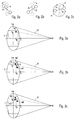
- FIGS. 3a to 3c briefly show the differences in Possibilities for creating additional marker arrangements Control signals are briefly explained.
- FIG. 3a shows a sketch for the use of a single active or passive marker M on the treatment instrument.
- the detection of this marker M permits the determination of its position within the area F placed in the viewing cone ⁇ of the camera K.
- the position of the marker M can then be converted into corresponding screen coordinates x p and y p for the pointer on the screen. Since there is only one marker M, additional control signals for simulating mouse clicks can only be generated by an additional input instrument - for example the foot switch - or by generating special light sequences.
- the orientation of the connecting straight line II relative to the x or y axis can also be determined.
- the angle ⁇ determined here can be used as described above - possibly with the help of a further switch or foot switch - to generate further control signals.
- the center between the two markers M1 and M2 is preferably chosen for the coordinates x p and y p of the pointer on the screen surface. If the two markers M1 and M2 are structurally identical, a reversal of their arrangement, which results, for example, when rotating through 180 °, cannot be detected, so that ambiguities can possibly arise.
- this arrangement has the disadvantage that the rotation of the instrument cannot be clearly determined, since the rotation of the instrument from any position results in exactly the same image of the marker arrangement.
- there is the possibility of avoiding this problem by designing or operating the markers in such a way that they can be clearly identified. This can be done, for example, using a different shape of the markers or by modulating the light signals emitted by the markers.
Applications Claiming Priority (2)
| Application Number | Priority Date | Filing Date | Title |
|---|---|---|---|
| DE19948620 | 1999-10-08 | ||
| DE19948620A DE19948620A1 (de) | 1999-10-08 | 1999-10-08 | Zahnmedizinische Einrichtung |
Publications (2)
| Publication Number | Publication Date |
|---|---|
| EP1090602A1 true EP1090602A1 (fr) | 2001-04-11 |
| EP1090602B1 EP1090602B1 (fr) | 2006-04-26 |
Family
ID=7925019
Family Applications (1)
| Application Number | Title | Priority Date | Filing Date |
|---|---|---|---|
| EP00120420A Expired - Lifetime EP1090602B1 (fr) | 1999-10-08 | 2000-09-18 | Dispositif dentaire |
Country Status (5)
| Country | Link |
|---|---|
| US (1) | US6506050B1 (fr) |
| EP (1) | EP1090602B1 (fr) |
| JP (1) | JP2001161723A (fr) |
| AT (1) | ATE324077T1 (fr) |
| DE (2) | DE19948620A1 (fr) |
Cited By (2)
| Publication number | Priority date | Publication date | Assignee | Title |
|---|---|---|---|---|
| WO2008101361A1 (fr) * | 2007-02-22 | 2008-08-28 | Lukas Kamer | Dispositif pour la planification et l'exécution d'une intervention chirurgicale |
| AT512350A1 (de) * | 2011-12-20 | 2013-07-15 | Isiqiri Interface Tech Gmbh | Computeranlage und steuerungsverfahren dafür |
Families Citing this family (13)
| Publication number | Priority date | Publication date | Assignee | Title |
|---|---|---|---|---|
| US6969254B2 (en) | 2001-12-18 | 2005-11-29 | Ivoclar Vivadent Ag. | Dental apparatus |
| DE10162231B4 (de) * | 2001-12-18 | 2006-07-13 | Ivoclar Vivadent Ag | Dentalgerät |
| US20050084816A1 (en) * | 2003-10-21 | 2005-04-21 | Mehdizadeh Bahman M. | Systems and methods for performing dental operations |
| FI125580B (en) * | 2004-04-02 | 2015-12-15 | Planmeca Oy | Data arrangement and procedure for quality assurance of dental care |
| FI20041289A (fi) | 2004-10-05 | 2006-04-06 | Planmeca Oy | Ohjausjärjestely ja menetelmä hammashoitokoneen yhteyteen järjestetyn tietokoneen ohjaamiseksi |
| CA2539271C (fr) * | 2005-03-31 | 2014-10-28 | Alcon, Inc. | Interrupteur au pied servant a commander un appareil de chirurgie |
| CA2629076A1 (fr) * | 2005-11-09 | 2007-05-18 | Primera Biosystems, Inc. | Detection multiplex quantitative d'agents pathogenes |
| US8465473B2 (en) * | 2007-03-28 | 2013-06-18 | Novartis Ag | Surgical footswitch with movable shroud |
| DE102008023468A1 (de) * | 2008-05-14 | 2009-11-19 | Siemens Aktiengesellschaft | Anordnung und Verfahren zur Bedienung von Geräten |
| DE102008023466A1 (de) * | 2008-05-14 | 2010-11-25 | Siemens Aktiengesellschaft | Anordnung und Verfahren zur Bedienung von Geräten |
| AR072011A1 (es) * | 2008-06-05 | 2010-07-28 | Alcon Res Ltd | Red inalambrica y metodos de comunicacion inalambrica para consolas quirurgicas oftalmicas |
| AT508094B1 (de) | 2009-03-31 | 2015-05-15 | Fronius Int Gmbh | Verfahren und vorrichtung zur bedienung einer mit einem handbetätigten arbeitsgerät verbundenen stromquelle |
| US10095650B2 (en) | 2016-04-04 | 2018-10-09 | A-Dec, Inc. | High speed controller area network (CAN) in dental equipment |
Citations (9)
| Publication number | Priority date | Publication date | Assignee | Title |
|---|---|---|---|---|
| DE3838605A1 (de) | 1988-11-15 | 1990-05-17 | Hartmut Schaefer | Geraet zur eingabe 3-dimensionaler koordinaten und bewegungen fuer computer |
| EP0391967B1 (fr) | 1987-12-22 | 1992-08-12 | Flex Dental A/S | Appareil dentaire commande par microprocesseur |
| EP0525539A2 (fr) | 1991-07-31 | 1993-02-03 | Ritter-IBW Dentalsysteme GmbH | Installation pour traitement dentaire et méthode de contrôle pour cela |
| EP0526015A1 (fr) | 1991-07-08 | 1993-02-03 | PEGASUS TECHNOLOGIES Ltd. | Souris tri-dimensionnelle pour ordinateur |
| US5230623A (en) | 1991-12-10 | 1993-07-27 | Radionics, Inc. | Operating pointer with interactive computergraphics |
| EP0455852B1 (fr) | 1990-05-09 | 1994-08-10 | Siemens Aktiengesellschaft | Dispositif médical et en particulier dentaire |
| EP0789320A2 (fr) | 1996-02-09 | 1997-08-13 | Pegasus Technologies Ltd. | Souris d'ordinateur et support |
| DE29621939U1 (de) | 1996-12-17 | 1998-04-16 | Kaltenbach & Voigt | Medizinische, insbesondere zahnmedizinische Einrichtung |
| US5828197A (en) * | 1996-10-25 | 1998-10-27 | Immersion Human Interface Corporation | Mechanical interface having multiple grounded actuators |
Family Cites Families (3)
| Publication number | Priority date | Publication date | Assignee | Title |
|---|---|---|---|---|
| AU4026093A (en) * | 1992-04-03 | 1993-11-08 | Foster-Miller Inc. | Method and apparatus for obtaining coordinates describing three-dimensional objects of complex and unique geometry using a sampling probe |
| KR0159070B1 (ko) * | 1994-06-09 | 1998-12-15 | 모리타 류이치로 | 근관길이 측정기능을 구비한 치과치료장치 |
| US5688118A (en) * | 1995-12-27 | 1997-11-18 | Denx Ltd. | Image sound and feeling simulation system for dentistry |
-
1999
- 1999-10-08 DE DE19948620A patent/DE19948620A1/de not_active Withdrawn
-
2000
- 2000-09-18 EP EP00120420A patent/EP1090602B1/fr not_active Expired - Lifetime
- 2000-09-18 AT AT00120420T patent/ATE324077T1/de not_active IP Right Cessation
- 2000-09-18 DE DE50012639T patent/DE50012639D1/de not_active Expired - Fee Related
- 2000-09-19 US US09/664,786 patent/US6506050B1/en not_active Expired - Fee Related
- 2000-10-10 JP JP2000309844A patent/JP2001161723A/ja not_active Withdrawn
Patent Citations (9)
| Publication number | Priority date | Publication date | Assignee | Title |
|---|---|---|---|---|
| EP0391967B1 (fr) | 1987-12-22 | 1992-08-12 | Flex Dental A/S | Appareil dentaire commande par microprocesseur |
| DE3838605A1 (de) | 1988-11-15 | 1990-05-17 | Hartmut Schaefer | Geraet zur eingabe 3-dimensionaler koordinaten und bewegungen fuer computer |
| EP0455852B1 (fr) | 1990-05-09 | 1994-08-10 | Siemens Aktiengesellschaft | Dispositif médical et en particulier dentaire |
| EP0526015A1 (fr) | 1991-07-08 | 1993-02-03 | PEGASUS TECHNOLOGIES Ltd. | Souris tri-dimensionnelle pour ordinateur |
| EP0525539A2 (fr) | 1991-07-31 | 1993-02-03 | Ritter-IBW Dentalsysteme GmbH | Installation pour traitement dentaire et méthode de contrôle pour cela |
| US5230623A (en) | 1991-12-10 | 1993-07-27 | Radionics, Inc. | Operating pointer with interactive computergraphics |
| EP0789320A2 (fr) | 1996-02-09 | 1997-08-13 | Pegasus Technologies Ltd. | Souris d'ordinateur et support |
| US5828197A (en) * | 1996-10-25 | 1998-10-27 | Immersion Human Interface Corporation | Mechanical interface having multiple grounded actuators |
| DE29621939U1 (de) | 1996-12-17 | 1998-04-16 | Kaltenbach & Voigt | Medizinische, insbesondere zahnmedizinische Einrichtung |
Cited By (3)
| Publication number | Priority date | Publication date | Assignee | Title |
|---|---|---|---|---|
| WO2008101361A1 (fr) * | 2007-02-22 | 2008-08-28 | Lukas Kamer | Dispositif pour la planification et l'exécution d'une intervention chirurgicale |
| AT512350A1 (de) * | 2011-12-20 | 2013-07-15 | Isiqiri Interface Tech Gmbh | Computeranlage und steuerungsverfahren dafür |
| AT512350B1 (de) * | 2011-12-20 | 2017-06-15 | Isiqiri Interface Tech Gmbh | Computeranlage und steuerungsverfahren dafür |
Also Published As
| Publication number | Publication date |
|---|---|
| ATE324077T1 (de) | 2006-05-15 |
| DE50012639D1 (de) | 2006-06-01 |
| EP1090602B1 (fr) | 2006-04-26 |
| US6506050B1 (en) | 2003-01-14 |
| JP2001161723A (ja) | 2001-06-19 |
| DE19948620A1 (de) | 2001-04-12 |
Similar Documents
| Publication | Publication Date | Title |
|---|---|---|
| EP1090602B1 (fr) | Dispositif dentaire | |
| DE19958443C2 (de) | Bedieneinrichtung | |
| EP1302172B1 (fr) | Instrument médical avec une pointe sensible au toucher | |
| DE4409862C2 (de) | Zahnärztliche Einrichtung mit ein oder mehreren unterschiedlich konfigurierten Instrumenten | |
| EP3305232B1 (fr) | Dispositif de commande et procede de commande pour l'opération d'un dispositif médical | |
| DE19956814A1 (de) | Formerfassung von Behandlungsvorrichtungen | |
| EP1854425A1 (fr) | Localisation spatiale pour appareils médicaux avec mesure de localisation redondante et pondération pour prioriser les mesures | |
| DE19817039A1 (de) | Anordnung für die bildgeführte Chirurgie | |
| DE19961971A1 (de) | Verfahren zur sicheren automatischen Nachführung eines Endoskops und Verfolgung (Tracking) eines chirurgischen Instrumentes mit einem Endoskopführungssystem (EFS) für die minimal invasive Chirurgie | |
| DE19548091A1 (de) | Einhand-Steuerelement für Bewegungssteuerungen, vorzugsweise von optischen Instrumenten | |
| DE102013108115A1 (de) | Verfahren und Vorrichtung zum Festlegen eines Arbeitsbereichs eines Roboters | |
| EP2830526B1 (fr) | Système de navigation médicale muni d'un écran tactile connecté sans fil | |
| DE4240531C1 (de) | Vorrichtung zur präzisen Eingabe von Positions- und Druckverteilungen an der menschlichen Hand in ein Datenverarbeitungsgerät | |
| WO2017081143A1 (fr) | Dispositif d'éclairage médical et dispositif de commande par gestes médical | |
| EP1347326A1 (fr) | Microscope chirurgical avec un système d'information | |
| DE3923024A1 (de) | Elektrochirurgiegeraet mit bedienungs-, anzeige- und sicherheitseinrichtung | |
| DE19918072A1 (de) | Bedienverfahren und Bedienvorrichtung für einen bildschirmgesteuerten Prozeß | |
| DE102014106865A1 (de) | Bediensystem für ein Operationsmikroskop mit automatischer Folge- oder Ausrichtungsvorrichtung, Verfahren und Operationsmikroskop | |
| WO2016198286A1 (fr) | Procédé et dispositif de détermination d'un mouvement volontaire d'un membre | |
| DE102020114416A1 (de) | System zur Überwachung einer Operationsleuchtenanordnung | |
| DE102020114426A1 (de) | Gerätesteuerung | |
| DE10259009B3 (de) | Bedieneinheit für ein optisches System | |
| EP1533639A1 (fr) | Système pour contrôler un microscope sans contact | |
| EP1260897A2 (fr) | Dispositif d'entrée avec un dispositif actionneur pour contrôler le positionnement d'un objet | |
| DE10332652A1 (de) | Messgerät und Verfahren zum Betreiben eines Messgeräts |
Legal Events
| Date | Code | Title | Description |
|---|---|---|---|
| PUAI | Public reference made under article 153(3) epc to a published international application that has entered the european phase |
Free format text: ORIGINAL CODE: 0009012 |
|
| AK | Designated contracting states |
Kind code of ref document: A1 Designated state(s): AT CH DE FI FR IT LI |
|
| AX | Request for extension of the european patent |
Free format text: AL;LT;LV;MK;RO;SI |
|
| 17P | Request for examination filed |
Effective date: 20011011 |
|
| AKX | Designation fees paid |
Free format text: AT CH DE FI FR IT LI |
|
| RAP1 | Party data changed (applicant data changed or rights of an application transferred) |
Owner name: KALTENBACH & VOIGT GMBH & CO. KG |
|
| 17Q | First examination report despatched |
Effective date: 20040726 |
|
| GRAP | Despatch of communication of intention to grant a patent |
Free format text: ORIGINAL CODE: EPIDOSNIGR1 |
|
| GRAS | Grant fee paid |
Free format text: ORIGINAL CODE: EPIDOSNIGR3 |
|
| GRAA | (expected) grant |
Free format text: ORIGINAL CODE: 0009210 |
|
| AK | Designated contracting states |
Kind code of ref document: B1 Designated state(s): AT CH DE FI FR IT LI |
|
| RAP1 | Party data changed (applicant data changed or rights of an application transferred) |
Owner name: KALTENBACH & VOIGT GMBH |
|
| REF | Corresponds to: |
Ref document number: 50012639 Country of ref document: DE Date of ref document: 20060601 Kind code of ref document: P |
|
| REG | Reference to a national code |
Ref country code: CH Ref legal event code: NV Representative=s name: A. BRAUN, BRAUN, HERITIER, ESCHMANN AG PATENTANWAE |
|
| PG25 | Lapsed in a contracting state [announced via postgrant information from national office to epo] |
Ref country code: FI Free format text: LAPSE BECAUSE OF NON-PAYMENT OF DUE FEES Effective date: 20060918 |
|
| PG25 | Lapsed in a contracting state [announced via postgrant information from national office to epo] |
Ref country code: CH Free format text: LAPSE BECAUSE OF NON-PAYMENT OF DUE FEES Effective date: 20060930 Ref country code: LI Free format text: LAPSE BECAUSE OF NON-PAYMENT OF DUE FEES Effective date: 20060930 |
|
| PGFP | Annual fee paid to national office [announced via postgrant information from national office to epo] |
Ref country code: IT Payment date: 20060930 Year of fee payment: 7 |
|
| ET | Fr: translation filed | ||
| PLBE | No opposition filed within time limit |
Free format text: ORIGINAL CODE: 0009261 |
|
| STAA | Information on the status of an ep patent application or granted ep patent |
Free format text: STATUS: NO OPPOSITION FILED WITHIN TIME LIMIT |
|
| 26N | No opposition filed |
Effective date: 20070129 |
|
| REG | Reference to a national code |
Ref country code: CH Ref legal event code: PL |
|
| REG | Reference to a national code |
Ref country code: FR Ref legal event code: ST Effective date: 20070531 |
|
| PGFP | Annual fee paid to national office [announced via postgrant information from national office to epo] |
Ref country code: DE Payment date: 20070926 Year of fee payment: 8 |
|
| PG25 | Lapsed in a contracting state [announced via postgrant information from national office to epo] |
Ref country code: AT Free format text: LAPSE BECAUSE OF NON-PAYMENT OF DUE FEES Effective date: 20060918 |
|
| PG25 | Lapsed in a contracting state [announced via postgrant information from national office to epo] |
Ref country code: FR Free format text: LAPSE BECAUSE OF NON-PAYMENT OF DUE FEES Effective date: 20061002 |
|
| PG25 | Lapsed in a contracting state [announced via postgrant information from national office to epo] |
Ref country code: DE Free format text: LAPSE BECAUSE OF NON-PAYMENT OF DUE FEES Effective date: 20090401 Ref country code: IT Free format text: LAPSE BECAUSE OF NON-PAYMENT OF DUE FEES Effective date: 20070918 |