EP1089835B1 - Method and device for producing straight bead welded pipes from flat sheet metal blanks - Google Patents
Method and device for producing straight bead welded pipes from flat sheet metal blanks Download PDFInfo
- Publication number
- EP1089835B1 EP1089835B1 EP99931143A EP99931143A EP1089835B1 EP 1089835 B1 EP1089835 B1 EP 1089835B1 EP 99931143 A EP99931143 A EP 99931143A EP 99931143 A EP99931143 A EP 99931143A EP 1089835 B1 EP1089835 B1 EP 1089835B1
- Authority
- EP
- European Patent Office
- Prior art keywords
- sheet metal
- halves
- metal blank
- longitudinal edges
- tool halves
- Prior art date
- Legal status (The legal status is an assumption and is not a legal conclusion. Google has not performed a legal analysis and makes no representation as to the accuracy of the status listed.)
- Expired - Lifetime
Links
Images


Classifications
-
- B—PERFORMING OPERATIONS; TRANSPORTING
- B21—MECHANICAL METAL-WORKING WITHOUT ESSENTIALLY REMOVING MATERIAL; PUNCHING METAL
- B21D—WORKING OR PROCESSING OF SHEET METAL OR METAL TUBES, RODS OR PROFILES WITHOUT ESSENTIALLY REMOVING MATERIAL; PUNCHING METAL
- B21D5/00—Bending sheet metal along straight lines, e.g. to form simple curves
- B21D5/06—Bending sheet metal along straight lines, e.g. to form simple curves by drawing procedure making use of dies or forming-rollers, e.g. making profiles
- B21D5/10—Bending sheet metal along straight lines, e.g. to form simple curves by drawing procedure making use of dies or forming-rollers, e.g. making profiles for making tubes
-
- B—PERFORMING OPERATIONS; TRANSPORTING
- B21—MECHANICAL METAL-WORKING WITHOUT ESSENTIALLY REMOVING MATERIAL; PUNCHING METAL
- B21C—MANUFACTURE OF METAL SHEETS, WIRE, RODS, TUBES OR PROFILES, OTHERWISE THAN BY ROLLING; AUXILIARY OPERATIONS USED IN CONNECTION WITH METAL-WORKING WITHOUT ESSENTIALLY REMOVING MATERIAL
- B21C37/00—Manufacture of metal sheets, bars, wire, tubes or like semi-manufactured products, not otherwise provided for; Manufacture of tubes of special shape
- B21C37/06—Manufacture of metal sheets, bars, wire, tubes or like semi-manufactured products, not otherwise provided for; Manufacture of tubes of special shape of tubes or metal hoses; Combined procedures for making tubes, e.g. for making multi-wall tubes
- B21C37/08—Making tubes with welded or soldered seams
- B21C37/0815—Making tubes with welded or soldered seams without continuous longitudinal movement of the sheet during the bending operation
-
- B—PERFORMING OPERATIONS; TRANSPORTING
- B21—MECHANICAL METAL-WORKING WITHOUT ESSENTIALLY REMOVING MATERIAL; PUNCHING METAL
- B21C—MANUFACTURE OF METAL SHEETS, WIRE, RODS, TUBES OR PROFILES, OTHERWISE THAN BY ROLLING; AUXILIARY OPERATIONS USED IN CONNECTION WITH METAL-WORKING WITHOUT ESSENTIALLY REMOVING MATERIAL
- B21C37/00—Manufacture of metal sheets, bars, wire, tubes or like semi-manufactured products, not otherwise provided for; Manufacture of tubes of special shape
- B21C37/06—Manufacture of metal sheets, bars, wire, tubes or like semi-manufactured products, not otherwise provided for; Manufacture of tubes of special shape of tubes or metal hoses; Combined procedures for making tubes, e.g. for making multi-wall tubes
- B21C37/15—Making tubes of special shape; Making tube fittings
- B21C37/16—Making tubes with varying diameter in longitudinal direction
Definitions
- a clamping and holding device for Slotted tubes of relatively short length are known (DE 44 32 674 C1), in which the slotted tube of it partially wrapping bands in a suitable Welding position for a along the joint gap movable welding device is held. To become one so it comes to longitudinally welded pipe required one in a separate device Form sheet metal blank into a slotted tube.
- both mold halves are not cylindrical Half shells, but with axially offset disks arcuate cutouts formed. With this Device is said to be a conical from a sheet metal blank Tube are formed. That is why the circular arc Cutouts of the washers in the axial direction increasing radius.
- the outer parts of the Mold halves an inner tapered mandrel assigned.
- this thorn is not during the effective throughout the molding process, but only at the end of the Molding process because it is in the middle between the Mold halves is placed on the sheet. Because of the lack of inner and outer guidance during the Despite such a thorn, the forming process becomes a danger the buckling of the sheet metal blank during the Form process not encountered.
- the invention has for its object a method and to create a device that allow it to Sheet metal blanks, especially those with thin ones Wall thickness to produce longitudinally welded pipes.
- the method and the device for Processing of sheet metal blanks of various thicknesses, for example tailored blanks.
- the invention thus proceeds from a method for Manufacture of a longitudinally welded tube from one flat sheet metal cut with parallel longitudinal edges, at which the sheet metal cutting with the help of two against each other movable, mirror images arranged to each other, having outer cylindrical half-shells Mold halves is formed into a slotted tube and then the longitudinal edges in the apex of the Molding tool are welded together, being held in position by the mold halves (see e.g. DE-C-966 111).
- Sheet metal cutting when molding through inner cylindrical Mandrel halves that fix the outer half shells are assigned and form columns with these, supported on the inside, with the one in the apex emerging longitudinal edges free for welding being held.
- the invention further relates to a device for Manufacture of longitudinally welded tubes from flat Sheet metal cuts with parallel longitudinal edges with two of a tool carrier, against each other movable, arranged in mirror image to each other and having outer cylindrical half-shells Mold halves emerging from an open Pick-up position for cutting the sheet into a closed position are movable, in which the longitudinal edges to be welded together from the closed mold halves in the upper Vertex are held together, and with an over the mold halves along in the welding position held longitudinal edges movable welding device (see e.g. DE-C-966 111).
- the invention is thereby characterized in that the mold halves the outer Half-shells fixedly assigned cylindrical inner mandrel halves have, with the outer half-shells for form the sheet metal blank to be inserted, the Form column in the closed position of the Mold halves emerging from the form gaps in the crown Keep longitudinal edges free for welding.
- tubes can be made from sheet metal blanks according to the invention short length in medium quantities economically produce. Both pipes with constant Produce wall thickness as well as pipes that have a different over their length or circumference Have wall thickness.
- the particular advantage of the invention is that the mold halves themselves shaped slot tube with the joint gap in an optimal Hold the welding position around the weld with the lengthways of the joining gap movable welding device manufacture. So there are no longer two separate ones Devices for reshaping and holding the Slot tube required in welding position. In order to there is also no labor-intensive reloading of the Slot tube with the then required alignment and Tighten.
- the sheet metal blank first with a Half all in one of the slots and then with his the other half inserted into the other slot becomes.
- One of the two mold halves, especially the movable one, near the entrance of the mold gap have an abutment on which at Moving the mold halves together a longitudinal edge the sheet metal blank can be supported. So that will Sheet metal cutting given a good guide that a Misalignment of the sheet metal blank when inserted in excludes the form gap.
- the Sheet metal cutting in those adjacent to the longitudinal edges narrow streaks at the exit or after the exit are reshaped from the mold gaps in such a way that they merge essentially tangentially. In terms of device, this can be done in two ways and Realize wise. Either is the top one Vertex area of the mold halves on the Longitudinal edges in the sense of bringing them together Tool assigned or the form column run to top vertex in a common plane.
- the Invention provided that one of the two Mold halves, especially the stationary, in top vertex a retractable stop for the longitudinal edge of the in this mold half deformed sheet metal blank is assigned. This The stop then also serves as a support when inserting of the sheet metal blank in the mold gap of the others Mold half.
- the stop preferably has one such asymmetrically formed tip that at Impact of the other longitudinal edge on this stop this recedes with the release of one longitudinal edge, both longitudinal edges meet and so one Form butt joint.
- the molding tool is dirty, according to one embodiment of the invention provided in the area of the upper vertex of the Arrange a drip tray inside the mandrel halves.
- a drip tray can be used after each use Welding device to be cleaned or replaced.
- the collecting tray is preferably arranged stationary and extends the entire length of the Mold halves. With such a configuration be further provided that they are close to the Inner mandrel halves are connected and with the free Longitudinal edge areas of the tube forms a channel. On such a channel is suitable for a protective gas purging or Extraction of the fumes generated during welding.
- the drip tray itself expediently consists of flexible material and has a V-shaped cross section. This configuration is particularly suitable because it can be easily connected to the mandrel halves and not moving the mold halves together hampers, but folds together.
- the drip tray can also be used with the Welding device be designed to migrate. That leaves can be realized constructively easily if it is provided that it is on the end face of a plunger Pushing out the inner mandrel halves is kept.
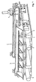
- a mold is on a tool carrier 1 constructed, which consists of two mold halves 2,3. Above the mold halves 2, 3 is by means of a trolley 4 a welding device 5 for longitudinal seam welding traversable. While the mold half 2 stationary is arranged on the tool carrier 1, the Mold half 3 mounted on linear guides 6 and by means of actuating cylinders 7 in the direction of the other Mold half 2 movable.
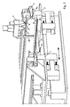
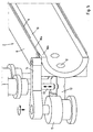
- the mold halves 2, 3 have essentially that same structure. They consist of an outer cylindrical half-shell 8, which extends in the longitudinal direction composed of individual sections and one in it fixed to form a gap 9 Inner mandrel half 10. At the front end (see Figure 2) the inner mandrel half 10 by means of a swivel arm 11 held on a front pin 11a Internal mandrel half 10 attacks. The inner mandrel half 10 has at the back end (see. Figures 4,5) an im Outer diameter enlarged section 10a, the is equal to the inner diameter of the half-shell 8. With the inner mandrel half 10 lies firmly against this section 10a the half shell 8. Section 10a faces the half shell 8 axially with a piece 10b.
- Section 10a in this piece 10b grip releasably Tension elements 12 on, which can be coupled by means of clamping pins 13 radially outwards and thus against the half-shell 8 can be pulled.
- Tension elements 12 on which can be coupled by means of clamping pins 13 radially outwards and thus against the half-shell 8 can be pulled.
- On the protruding piece 10b can by means of a swivel arm 14 and a Actuating cylinder 15 a pivoting moment around a horizontal axis extending transversely to the longitudinal direction. The function will later be related to the Removal of a finished pipe still received.
- the fixation of the Inner mandrel half 10 also through the half shell 8 more or less radially penetrating fixing pins can be realized that are transverse to the longitudinal axis of the mold are movable and provided in the inner mandrel halves Engage recesses. This will make the inner mandrel half 10 axially and radially supported and fixed.
- the fixing mandrels at an angle of approx. 45 ° to vertical plane of symmetry.
- Support structure 18 for the sheet metal blank to be formed B provided.
- This support structure 18 serves the Record sheet metal cut B and a buckling after below during insertion into the mold gap 9 prevent.
- the support structure 18 consists in detail of several parallel to each other and across Longitudinal direction of the device stationary on the Tool carrier 1 arranged carriers 19 and on each Forming gap arranged baffles 20,21 by resilient supported guides 22,23 are worn.
- the guide plates 20, 21 At the Support moving the mold halves 2, 3 together the guide plates 20, 21 the insertion of the sheet metal blank B into the form column 9, with a buckling of the with his Dead weight resting on the supports 19 Sheet metal blank B is prevented by the carrier 19. They give way because of the resilient support of the guide plates at the end of this forming process so that the Mold halves 2, 3 completely moved together can be.
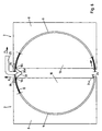
- the inner mandrel half 10 (see FIGS. 6, 7) of one Mold half 3 has one on the lower vertex Projection 24 and above an abutment 24a. Thereon and this is supported by a longitudinal edge of the Sheet metal blank B when it is introduced into the mold gap 9 of the other mold half 2.
- the mold half 2 is in its upper apex in the direction of arrows P2, P3 movable stop 25 with assigned an asymmetrical tip 26 such that the sheet metal blank B inserted into the gap 9 with its longitudinal edge on the vertical flank of the stop 25, ie above a short slope 26a, strikes.
- An opposite cutting edge 26b is much longer and is in the area of the exit of the other mold gap 9, so that the emerging here Sheet metal cut with its longitudinal edge on the slope 26b incident.
- the half-shell 8 and the inner mandrel half 10 can Apex in horizontal sections 8b, 10c leak.
- This configuration serves the Longitudinal edges in an even better position for that Bring welding.
- the Carriage 4 have a pressure roller 27, the Welding device 5 is arranged upstream and the longitudinal edges depressing.
- the top is Vertex area of the mold halves 2,3 a stationary collecting tray 30 arranged as a V-shaped Profile with angled ends is formed with which they on the sections 10c rests.
- This drip tray 30 is flexible, in particular, it is made of sheet metal, so that it Moving the mold halves together 2.3 can be folded together. It extends over the entire length of the mold halves 2, 3 and serves to Collect waste materials generated during welding. she forms with the merged ends of the from the Sheet metal blank 13 shaped tube for a channel 30a a protective gas purge or can serve as a suction channel.
- Drip tray An alternative embodiment for the is not shown Drip tray.
- this alternative version is a shell running with the welding device 5 intended.
- This bowl can be on the forehead of a pestle be arranged with the inner arbors 10 accordingly the progress of the weld are pushed out.
- the mold gap has either in A circumferential direction or in the longitudinal direction accordingly the different thickness of the sheet Wide.
- sheet metal cuts with low Thickness differences of up to approx. 0.1 mm can Form gap have a constant width because these are small Thickness differences in the range in each case provided oversize of the mold gap.
- the operation of the device according to the invention is the following: As shown in Figure 3, is in the open Forming tool halves 2,3 with a sheet metal blank B. parallel longitudinal edges on the supporting structure 18 hung up. With the right longitudinal edge in the drawing the sheet metal blank B in the gap 9 of the Mold half 2 threaded. The left long edge is on the approach 24 of the inner mandrel half 10 of the other Mold half 3 placed so that the Sheet metal blank B with this longitudinal edge on the abutment 24a supports. The abutment 24a offers that Sheet blank B precise guidance, so that the Sheet metal blank B in the form gap 9 can not tilt. Now the mold half 3 in the direction of Move mold half 2. The Sheet metal blank B inserted into the gap 9 until its right longitudinal edge is near the support members 16 is located.
- the mold half 3 becomes a little retracted until the left longitudinal edge is supported on the approach 24 no longer exists.
- the sheet metal blank B is then with its left longitudinal edge in the mold gap 9 of the mold half 3 and the Mold half 3 in the direction of mold half 2 method.
- Removing the support members of the Inner mandrel half is done in the same way as the right half of mandrel.
- the stop 25 through the longitudinal edge in Arrow direction P2 moved upwards. With this movement the right longitudinal edge also reaches the slope 26a and is released so that the next Push the longitudinal edges together exactly in the desired one Meet welding position.
- the Stop 25 by means not shown from the Area of the apex removed and the joint gap for the Longitudinal seam welding released. If necessary, you can the sheet edges by pressing means before welding be reshaped to the springing of the sheet metal edges to compensate for the elasticity of the material and to obtain a parallel joint gap.
Abstract
Description
Es sind verschiedene Verfahren und Vorrichtungen zum Herstellen von längsnahtgeschweißten Rohren aus Bändern und Blechzuschnitten bekannt, die allerdings keine wirtschaftliche Herstellung von Rohren verhältnismäßig kurzer Länge (zum Beispiel l = 3.000 mm), kleinem Durchmesser (zum Beispiel d = 50 mm) und relativ großer Wandstärke (zum Beispiel s = 2,5 mm) in mittleren Stückzahlen ermöglichen. Ziel der Erfindung ist es deshalb, ein Verfahren und eine Vorrichtung für die Herstellung derartiger Rohre zu schaffen.There are various methods and devices for Manufacture of longitudinally welded tubes from strips and sheet metal cuts known, but none economical production of pipes short length (for example l = 3,000 mm), small Diameter (for example d = 50 mm) and relatively large Wall thickness (for example s = 2.5 mm) in medium Enable quantities. The aim of the invention is therefore, a method and an apparatus for the To create manufacture of such pipes.
Beim bekannten Verfahren des Rollformens (US-A-2,110,378) wird ein Band in mehreren hintereinander angeordneten Stufen von angetriebenen profilierten Rollen zu einem Schlitzrohr umgeformt, das anschließend geschweißt wird. Der Investitionsaufwand für eine dafür geeignete Anlage ist sehr hoch, so daß sie sich nicht für die Herstellung von Rohren mittlerer Stückzahl eignet.In the known method of roll forming (US-A-2,110,378) a band is arranged in several one after the other Steps from driven profiled rollers to one Slotted tube formed, which is then welded. The investment for a suitable system is very high, so it is not for manufacturing of medium-sized pipes.
Beim bekannten 3-Walzenbiegen wird ein ebener Blechzuschnitt mit zwei Stützwalzen um eine Arbeitswalze herum gebogen. Mit einem solchen Verfahren lassen sich Rohre mit einer Wanddicke von zum Beispiel 1,0 mm und einem Durchmesser von 50 mm nur mit einer Länge von unter 2.000 mm herstellen, weil sich die Stützrollen wegen der aufzubringenden großen Stützkräfte durchbiegen. Hinzu kommt, daß das hergestellte Schlitzrohr der Vorrichtung entnommen und an anderer Stelle längsnahtgeschweißt werden muß.In the known 3-roll bending, a flat one is used Sheet metal cutting with two backup rolls around a work roll bent around. With such a procedure can be Pipes with a wall thickness of, for example, 1.0 mm and a diameter of 50 mm only with a length of less than Manufacture 2,000 mm because the support rollers because of the deflect large supporting forces to be applied. in addition comes that the manufactured slit tube of the device removed and longitudinally welded elsewhere must become.
Ferner ist eine Spann- und Haltevorrichtung für Schlitzrohre verhältnismäßig kurzer Länge bekannt (DE 44 32 674 C1), bei der das geschlitzte Rohr von es teilweise umschlingenden Bändern in einer geeigneten Schweißposition für eine längs des Fügespaltes verfahrbare Schweißvorrichtung gehalten wird. Um zu einem längsnahtgeschweißten Rohr zu kommen, ist es also erforderlich, in einer separaten Vorrichtung einen Blechzuschnitt zu einem Schlitzrohr umzuformen.Furthermore, a clamping and holding device for Slotted tubes of relatively short length are known (DE 44 32 674 C1), in which the slotted tube of it partially wrapping bands in a suitable Welding position for a along the joint gap movable welding device is held. To become one so it comes to longitudinally welded pipe required one in a separate device Form sheet metal blank into a slotted tube.
Bei einer anderen bekannten Vorrichtung (DE-PS 966 111) zum Herstellen von längsnahtgeschweißten Rohren aus ebenen Blechzuschnitten mit parallelen Längskanten wird der Blechzuschnitt in ein und derselben Vorrichtung zum Schlitzrohr umgeformt und durch die das Rohr umformenden Mittel mit den zu verschweißenden Längskanten in Schweißposition gehalten. Zwei von einem Werkzeugträger getragene, gegeneinander verfahrbare, spiegelbildlich zueinander angeordnete und äußere zylindrische Halbschalen aufweisende Formwerkzeughälften nehmen in ihrer geöffneten Aufnahmeposition den Blechzuschnitt an seinen beiden Längskanten auf. Beim Zusammenfahren der Formwerkzeughälften wird der Blechzuschnitt an seinen beiden Enden in der Mitte fixiert gehalten, so daß sich der Blechzuschnitt beidseitig an den zylindrischen Halbschalen entlang schiebt, bis seine Längskanten im Scheitelpunkt aufeinandertreffen. In dieser Position wird der zu einem Schlitzrohr umgeformte Blechzuschnitt gehalten. Um dann die Längskanten miteinander zu verschweißen, können die oberen Enden der Formwerkzeughälften aufgeklappt werden, so daß der Fügespalt freigegeben wird. Ein wesentlicher Nachteil einer solchen Vorrichtung besteht darin, daß die Gefahr besteht, daß der Blechzuschnitt mangels innerer und äußerer Führung ausknickt. Diese Gefahr ist besonders groß bei dünnwandigen Blechzuschnitten.In another known device (DE-PS 966 111) for the manufacture of longitudinally welded pipes flat sheet metal blanks with parallel longitudinal edges the sheet metal blank in one and the same device for Slotted tube formed and by the tube forming Medium with the longitudinal edges to be welded in Welding position maintained. Two from a tool carrier worn, mutually movable, mirror image mutually arranged and outer cylindrical Half-shell mold halves take in the sheet metal blank in its open recording position its two long edges. When moving the Half of the mold will be cut to the sheet metal both ends held fixed in the middle, so that the sheet metal blank on both sides of the cylindrical Half shells along until its long edges in Vertex meet. In this position the sheet metal blank formed into a slotted tube held. Then the longitudinal edges together can weld the top ends of the Mold halves are opened so that the Joining gap is released. A major disadvantage such a device is that the danger there is that the sheet metal blank due to lack of internal and outer guide buckles. This danger is special large for thin-walled sheet metal blanks.
Bei einer sehr ähnlichen bekannten Vorrichtung zum Umformen von Blechzuschnitten zu Rohren und anschließendem Schweißen (DE-PS 593 622) werden die beiden Formwerkzeughälften nicht von zylindrischen Halbschalen, sondern von axial versetzten Scheiben mit kreisbogenförmigen Ausschnitten gebildet. Mit dieser Vorrichtung soll aus einem Blechzuschnitt ein konisches Rohr geformt werden. Deshalb haben die kreisbogenförmigen Ausschnitte der Scheiben in axialer Richtung einen zunehmenden Radius. Bei dieser bekannten Vorrichtung ist allerdings im Unterschied zur anderen vorbeschriebenen bekannten Vorrichtung den äußeren Teilen der Formwerkzeughälften ein innerer konischer Dorn zugeordnet. Dieser Dorn ist allerdings nicht während des gesamten Formvorgangs wirksam, sondern erst zum Ende des Formvorgangs, weil er in der Mitte zwischen den Formwerkzeughälften auf das Blech gelegt wird. Wegen der fehlenden inneren und äußeren Führung während des Umformvorganges wird trotz eines solchen Dorns der Gefahr des Ausknickens des Blechzuschnittes während des Formvorgangs nicht begegnet.In a very similar known device for Forming sheet metal blanks into tubes and subsequent welding (DE-PS 593 622) both mold halves are not cylindrical Half shells, but with axially offset disks arcuate cutouts formed. With this Device is said to be a conical from a sheet metal blank Tube are formed. That is why the circular arc Cutouts of the washers in the axial direction increasing radius. In this known device however, in contrast to the other previously described known device the outer parts of the Mold halves an inner tapered mandrel assigned. However, this thorn is not during the effective throughout the molding process, but only at the end of the Molding process because it is in the middle between the Mold halves is placed on the sheet. Because of the lack of inner and outer guidance during the Despite such a thorn, the forming process becomes a danger the buckling of the sheet metal blank during the Form process not encountered.
Der Erfindung liegt die Aufgabe zugrunde, ein Verfahren und eine Vorrichtung zu schaffen, die es erlauben, aus Blechzuschnitten, insbesondere solchen mit dünner Wandstärke, längsnahtgeschweißte Rohre herzustellen. Insbesondere soll das Verfahren und die Vorrichtung zur Verarbeitung von Blechzuschnitten verschiedener Dicke, zum Beispiel sogenannten tailored blanks, geeignet sein.The invention has for its object a method and to create a device that allow it to Sheet metal blanks, especially those with thin ones Wall thickness to produce longitudinally welded pipes. In particular, the method and the device for Processing of sheet metal blanks of various thicknesses, for example tailored blanks.
Die Erfindung geht somit von einem Verfahren zum Herstellen eines längsnahtgeschweißten Rohres aus einem ebenen Blechzuschnitt mit parallelen Längskanten aus, bei dem der Blechzuschnitt mit Hilfe von zwei gegeneinander verfahrbaren, spiegelbildlich zueinander angeordneten, äußere zylindrische Halbschalen aufweisenden Formwerkzeughälften zu einem Schlitzrohr umgeformt wird und anschließend die Längskanten im Scheitel des Formwerkzeuges miteinander verschweißt werden, wobei sie von den Formwerkzeughälften in Position gehalten werden (siehe z.B. DE-C-966 111). Bei einem solchen Verfahren wird erfindungsgemäß der Blechzuschnitt beim Einformen durch innere zylindrische Dornhälften, die den äußeren Halbschalen fixiert zugeordnet sind und mit diesen Formspalte bilden, innenseitig abgestützt, wobei die im Scheitel austretenden Längskanten für das Verschweißen frei gehalten werden.The invention thus proceeds from a method for Manufacture of a longitudinally welded tube from one flat sheet metal cut with parallel longitudinal edges, at which the sheet metal cutting with the help of two against each other movable, mirror images arranged to each other, having outer cylindrical half-shells Mold halves is formed into a slotted tube and then the longitudinal edges in the apex of the Molding tool are welded together, being held in position by the mold halves (see e.g. DE-C-966 111). at Such a method according to the invention Sheet metal cutting when molding through inner cylindrical Mandrel halves that fix the outer half shells are assigned and form columns with these, supported on the inside, with the one in the apex emerging longitudinal edges free for welding being held.
Die Erfindung betrifft ferner eine Vorrichtung zum Herstellen von längsnahtgeschweißten Rohren aus ebenen Blechzuschnitten mit parallelen Längskanten mit zwei von einem Werkzeugträger getragenen, gegeneinander verfahrbaren, spiegelbildlich zueinander angeordneten und äußere zylindrische Halbschalen aufweisenden Formwerkzeughälften, die aus einer geöffneten Aufnahmeposition für den Blechzuschnitt in eine geschlossene Position verfahrbar sind, in der die miteinander zu verschweißenden Längskanten von den geschlossenen Formwerkzeughälften in deren oberem Scheitelpunkt zusammengehalten werden, und mit einer über den Formwerkzeughälften entlang den in Schweißposition gehaltenen Längskanten verfahrbaren Schweißvorrichtung (siehe z.B. DE-C-966 111). The invention further relates to a device for Manufacture of longitudinally welded tubes from flat Sheet metal cuts with parallel longitudinal edges with two of a tool carrier, against each other movable, arranged in mirror image to each other and having outer cylindrical half-shells Mold halves emerging from an open Pick-up position for cutting the sheet into a closed position are movable, in which the longitudinal edges to be welded together from the closed mold halves in the upper Vertex are held together, and with an over the mold halves along in the welding position held longitudinal edges movable welding device (see e.g. DE-C-966 111).
Bei einer solchen Vorrichtung ist die Erfindung dadurch gekennzeichnet, daß die Formwerkzeughälften den äußeren Halbschalen fixiert zugeordnete zylindrische Innendornhälften aufweisen, die mit den äußeren Halbschalen Formspalte für den einzuschiebenden Blechzuschnitt bilden, wobei die Formspalte in der geschlossenen Position der Formwerkzeughälften die aus den Formspalten im Scheitel austretenden Längskanten für das Verschweißen frei halten.With such a device, the invention is thereby characterized in that the mold halves the outer Half-shells fixedly assigned cylindrical inner mandrel halves have, with the outer half-shells for form the sheet metal blank to be inserted, the Form column in the closed position of the Mold halves emerging from the form gaps in the crown Keep longitudinal edges free for welding.
Mit dem erfindungsgemäßen Verfahren und der erfindungsgemäßen Vorrichtung lassen sich Blechzuschnitte unterschiedlicher Dicke zu einem zylindrischen Rohr umformen, ohne daß die Gefahr besteht, daß beim Umformvorgang der Zuschnitt ausknickt. Insbesondere lassen sich nach der Erfindung aus Blechzuschnitten Rohre kurzer Länge in mittleren Stückzahlen wirtschaftlich herstellen. Es lassen sich sowohl Rohre mit konstanter Wandstärke als auch solche Rohre herstellen, die eine über ihre Länge oder ihren Umfang unterschiedliche Wandstärke haben. Der besondere Vorteil der Erfindung besteht darin, daß die Formwerkzeughälften selbst das geformte Schlitzrohr mit dem Fügespalt in einer optimalen Schweißposition halten, um die Schweißnaht mit der längs des Fügespaltes verfahrbaren Schweißvorrichtung herzustellen. Es sind also nicht länger zwei separate Vorrichtungen für das Umformen und das Halten des Schlitzrohres in Schweißposition erforderlich. Damit entfällt auch das arbeitsaufwendige Umladen des Schlitzrohres mit dem dann erforderlichen Ausrichten und Spannen.With the inventive method and Device according to the invention can be sheet metal blanks different thickness to a cylindrical tube reshape without the risk that the Forming process, the blank folds out. In particular tubes can be made from sheet metal blanks according to the invention short length in medium quantities economically produce. Both pipes with constant Produce wall thickness as well as pipes that have a different over their length or circumference Have wall thickness. The particular advantage of the invention is that the mold halves themselves shaped slot tube with the joint gap in an optimal Hold the welding position around the weld with the lengthways of the joining gap movable welding device manufacture. So there are no longer two separate ones Devices for reshaping and holding the Slot tube required in welding position. In order to there is also no labor-intensive reloading of the Slot tube with the then required alignment and Tighten.
Nach einer ersten Ausgestaltung der Erfindung ist vorgesehen, daß der Blechzuschnitt zunächst mit einer Hälfte ganz in einen der Formschlitze und dann mit seiner anderen Hälfte in den anderen Formschlitz eingeschoben wird. Dabei kann eine der beiden Formwerkzeughälften, insbesondere die verfahrbare, in der Nähe des Eingangs des Formspaltes ein Widerlager aufweisen, an dem beim Zusammenfahren der Formwerkzeughälften eine Längskante des Blechzuschnittes abstützbar ist. Damit wird dem Blechzuschnitt eine gute Führung gegeben, die ein Schiefstellen des Blechzuschnittes beim Einschieben in den Formspalt ausschließt.According to a first embodiment of the invention provided that the sheet metal blank first with a Half all in one of the slots and then with his the other half inserted into the other slot becomes. One of the two mold halves, especially the movable one, near the entrance of the mold gap have an abutment on which at Moving the mold halves together a longitudinal edge the sheet metal blank can be supported. So that will Sheet metal cutting given a good guide that a Misalignment of the sheet metal blank when inserted in excludes the form gap.
Zur Verbesserung der Geometrie des Fügespaltes kann der Blechzuschnitt in den an den Längskanten angrenzenden schmalen Streifen beim Austritt oder nach dem Austritt aus den Formspalten derart nachgeformt werden, daß sie im wesentlichen tangential ineinander übergehen. Vorrichtungsmäßig läßt sich dies auf zweierlei Art und Weise verwirklichen. Entweder ist dem oberen Scheitelbereich der Formwerkzeughälften ein auf die Längskanten im Sinne ihrer Zusammenführung einwirkendes Werkzeug zugeordnet oder aber die Formspalte laufen zum oberen Scheitelpunkt in einer gemeinsamen Ebene aus.To improve the geometry of the joint gap, the Sheet metal cutting in those adjacent to the longitudinal edges narrow streaks at the exit or after the exit are reshaped from the mold gaps in such a way that they merge essentially tangentially. In terms of device, this can be done in two ways and Realize wise. Either is the top one Vertex area of the mold halves on the Longitudinal edges in the sense of bringing them together Tool assigned or the form column run to top vertex in a common plane.
Die gewünschte räumliche Fixierung der Innendornhälften in den äußeren Halbschalen mit der Möglichkeit, das geformte Rohr entnehmen zu können, kann nach einer weiteren Ausgestaltung der Erfindung dadurch verwirklicht werden, daß die äußeren Halbschalen und die Innendornhälften einer jeden Formwerkzeughälfte an einem ihrer Enden miteinander verbunden sind und die Innendornhälfte mit ihrem anderen Ende unmittelbar am Werkzeugträger lösbar festgelegt ist, während die Innendornhälften im übrigen von mehreren Stützgliedern in Position gehalten sind, die die äußere Halbschale durch Ausnehmungen durchgreifen und über eine Schiebekupplung an der Innendornhälfte in Richtung des Scheitels der äußeren Halbschale abkuppelbar sind. Bei dieser Ausgestaltung ergibt sich eine steife Zuordnung von Halbschale und Innendornhälfte auch auf Teilbereichen der Länge der Innendornhälfte.The desired spatial fixation of the inner mandrel halves in the outer half shells with the possibility of the To be able to remove the shaped tube can realized further embodiment of the invention be that the outer half-shells and the Inner mandrel halves of each mold half on one their ends are connected and the Inner mandrel half with its other end immediately on Tool carrier is releasably set while the Internal mandrel halves in the rest of several support members in Position held by the outer half-shell Reach through recesses and a sliding coupling on the inner half of the mandrel towards the apex of the outer half shell can be uncoupled. At this Design results in a rigid assignment of Half-shell and half-mandrel also on parts of the Length of the inner mandrel half.
Diese Ausgestaltung läßt sich im einzelnen dadurch konstruktiv verwirklichen, daß die äußere Halbschale und die damit an einem Ende verbundene Innendornhälfte in diesem Verbindungsabschnitt spaltfrei aneinander liegen und durch lösbare Spannelemente zusammengehalten werden. So ergibt sich eine sehr präzise Zuordnung von Halbschale und Innendornhälfte mit einfacher Montagemöglichkeit. Die lösbaren Spannelemente erlauben es, den Formspalt etwas zu öffnen, um das fertige Rohr aus dem Formwerkzeug herauszuziehen oder sogar um die Innendornhälften aus dem fertigen Rohr herauszuziehen.This configuration can be individually constructively realize that the outer half-shell and the inner mandrel half connected at one end in this connection section lie against each other without gaps and held together by releasable clamping elements. This results in a very precise assignment of the half-shell and inner mandrel half with easy installation options. The Detachable clamping elements allow the form gap to be somewhat to open the finished pipe from the mold pull out or even around the inner mandrel halves pull out the finished pipe.
Um bei gelöstem vorderen Ende der Innendornhälfte das Rohr aus dem Formwerkzeug herausziehen zu können, ohne daß die Innendornhälfte durch Auflage auf dem Rohr das Herausziehen erschwert, sieht eine Ausgestaltung vor, daß die Innendornhälfte gegenüber der äußeren Halbschale an dem verbundenen Ende vorsteht und dem vorstehenden Stück ein Druckelement zugeordnet ist, mit dem auf die Innendornhälfte ein Schwenkmoment um eine horizontale Querachse im Sinne einer Entlastung des vorderen Endes der Innendornhälfte aufbringbar ist.To do this with the front end of the inner mandrel half loosened To be able to pull the pipe out of the mold without that the inner mandrel half by resting on the tube Difficult to pull out, provides an embodiment that the inner mandrel half opposite the outer half shell protrudes the connected end and the above piece is assigned a pressure element with which on the Inside mandrel half a swivel moment around a horizontal Transverse axis in the sense of relieving the front end the inner mandrel half can be applied.
Um ein Ausknicken des Blechzuschnittes zu vermeiden, wenn der Blechzuschnitt in die Formspalte eingeschoben wird, ist vorgesehen, daß unmittelbar unter und in der Aufnahmeposition zwischen den Formwerkzeughälften eine höhenverstellbare Tragkonstruktion für den in die Formspalte einzuführenden Blechzuschnitt vorgesehen ist. Diese Tragkonstruktion weist vorzugsweise am Eingang eines jeden Formspaltes ein sich über die gesamte Länge des Formspaltes erstreckendes und in Verfahrrichtung der Formwerkzeughälften federnd abgestütztes Leitblech auf. Diese Leitbleche weichen zurück, wenn die Formwerkzeughälften am Ende der Formgebung in die geschlossene Position gelangen.To prevent the sheet metal blank from buckling, if the sheet metal blank is inserted into the mold gap, it is envisaged that immediately below and in the Pick-up position between the mold halves height-adjustable support structure for the in the Form gap to be introduced sheet metal blank is provided. This support structure preferably faces the entrance of each mold gap over the entire length of the mold gap and in the direction of travel Mold halves resiliently supported baffle. These baffles retreat when the Mold halves at the end of the molding in the closed position.
Die genaue Positionierung der Längskanten im oberen Scheitelpunkt der Formwerkzeughälften für die Längsnahtschweißung läßt sich mit einfachen Mitteln gewährleisten. Dazu ist nach einer Ausgestaltung der Erfindung vorgesehen, daß einer der beiden Formwerkzeughälften, insbesondere der ortsfesten, im oberen Scheitelpunkt ein zurückbeweglicher Anschlag für die Längskante des in dieser Formwerkzeughälfte umgeformten Blechzuschnittes zugeordnet ist. Dieser Anschlag dient dann auch als Abstützung beim Einschieben des Blechzuschnittes in den Formspalt der anderen Formwerkzeughälfte. Vorzugsweise weist der Anschlag eine derart asymmetrisch ausgebildete Spitze auf, daß beim Auftreffen der anderen Längskante auf diesen Anschlag dieser unter Freigabe der einen Längskante zurückweicht, beide Längskanten aufeinandertreffen und so einen Stumpfstoß bilden.The exact positioning of the longitudinal edges in the upper one Vertex of the mold halves for the Longitudinal seam welding can be done with simple means guarantee. According to one embodiment, the Invention provided that one of the two Mold halves, especially the stationary, in top vertex a retractable stop for the longitudinal edge of the in this mold half deformed sheet metal blank is assigned. This The stop then also serves as a support when inserting of the sheet metal blank in the mold gap of the others Mold half. The stop preferably has one such asymmetrically formed tip that at Impact of the other longitudinal edge on this stop this recedes with the release of one longitudinal edge, both longitudinal edges meet and so one Form butt joint.
Um zu verhindern, daß beim Schweißen entstehender Schmutz, wie Schmelzspritzer oder Schmauch (zum Beispiel verdampftes Zink bei verzinkten Blechen) das Formwerkzeug verschmutzt, ist nach einer Ausgestaltung der Erfindung vorgesehen, im Bereich des oberen Scheitels der Innendornhälften eine Auffangschale anzuordnen. Eine solche Auffangschale kann nach jeder Benutzung der Schweißvorrichtung gereinigt oder ausgewechselt werden.To prevent welding Dirt, such as melt spatter or smoke (for example evaporated zinc in the case of galvanized sheets) the molding tool is dirty, according to one embodiment of the invention provided in the area of the upper vertex of the Arrange a drip tray inside the mandrel halves. A Such a collecting tray can be used after each use Welding device to be cleaned or replaced.
Vorzugsweise ist die Auffangschale stationär angeordnet und erstreckt sich über die gesamte Länge der Formwerkzeughälften. Bei einer solchen Ausgestaltung kann weiter vorgesehen sein, daß sie dicht an den Innendornhälften angeschlossen ist und mit den freien Längskantenbereichen des Rohres einen Kanal bildet. Ein solcher Kanal eignet sich für eine Schutzgasspülung oder Absaugung der beim Schweißen entstehenden Dämpfe.The collecting tray is preferably arranged stationary and extends the entire length of the Mold halves. With such a configuration be further provided that they are close to the Inner mandrel halves are connected and with the free Longitudinal edge areas of the tube forms a channel. On such a channel is suitable for a protective gas purging or Extraction of the fumes generated during welding.
Die Auffangschale selbst besteht zweckmäßigerweise aus flexiblem Material und hat einen V-förmigen Querschnitt. Diese Ausgestaltung eignet sich besonders gut, weil sie sich leicht an den Innendornhälften anschließen läßt und das Zusammenfahren der Formwerkzeughälften nicht behindert, sondern sich dabei zusammenfaltet.The drip tray itself expediently consists of flexible material and has a V-shaped cross section. This configuration is particularly suitable because it can be easily connected to the mandrel halves and not moving the mold halves together hampers, but folds together.
Alternativ kann die Auffangschale aber auch mit der Schweißvorrichtung mitwandernd ausgebildet sein. Das läßt sich konstruktiv leicht dann verwirklichen, wenn vorgesehen ist, daß sie stirnseitig an einem Stößel zum Ausschieben der Innendornhälften gehalten ist.Alternatively, the drip tray can also be used with the Welding device be designed to migrate. That leaves can be realized constructively easily if it is provided that it is on the end face of a plunger Pushing out the inner mandrel halves is kept.
Im folgenden wird die Erfindung anhand einer Zeichnung näher erläutert, die ein Ausführungsbeispiel zeigt. Im einzelnen zeigen:
- Figur 1
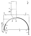
- eine Vorrichtung zum Herstellen von längsnahtgeschweißten Rohren aus ebenen Blechzuschnitten in perspektivischer Darstellung,
Figur 2- die Vorrichtung gemäß Figur 1 in einem vergrößerten Ausschnitt von der Vorderseite gesehen in perspektivischer Darstellung,
Figur 3- die Vorrichtung gemäß Figur 1 in Vorderansicht,
- Figur 4
- die Vorrichtung gemäß Figur 1 in einem vergrößerten Ausschnitt von der Rückseite gesehen in perspektivischer Darstellung,
Figur 5- die Vorrichtung gemäß Figur 1 in einem vergrößerten Ausschnitt und aus einer anderen Perspektive als Figur 4 von der Rückseite aus gesehen in perspektivischer Darstellung,
- Figur 6
- zwei Formwerkzeughälften der Vorrichtung gemäß Figur 1 in Vorderansicht und in vereinfachter Darstellung
- Figur 7
- eine Formwerkzeughälfte der Figur 6 in Vorderansicht mit zusätzlichen Details.
- Figure 1
- a device for producing longitudinally welded tubes from flat sheet metal blanks in a perspective view,
- Figure 2
- 2 shows the device according to FIG. 1 in an enlarged detail seen from the front in a perspective view,
- Figure 3
- 2 the device according to FIG. 1 in front view,
- Figure 4
- 1 shows the device according to FIG. 1 in an enlarged detail from the rear in a perspective view,
- Figure 5
- 1 in an enlarged detail and from a different perspective than FIG. 4 seen from the rear in a perspective view,
- Figure 6
- two mold halves of the device according to Figure 1 in front view and in a simplified representation
- Figure 7
- a mold half of Figure 6 in front view with additional details.
Auf einem Werkzeugträger 1 ist ein Formwerkzeug
aufgebaut, das aus zwei Formwerkzeughälften 2,3 besteht.
Über den Formwerkzeughälften 2,3 ist mittels eines Wagens
4 eine Schweißvorrichtung 5 zum Längsnahtschweißen
verfahrbar. Während die Formwerkzeughälfte 2 stationär
auf dem Werkzeugträger 1 angeordnet ist, ist die
Formwerkzeughälfte 3 auf Linearführungen 6 gelagert und
mittels Stellzylindern 7 in Richtung auf die andere
Formwerkzeughälfte 2 verfahrbar. A mold is on a tool carrier 1
constructed, which consists of two
Die Formwerkzeughälften 2,3 haben im wesentlichen den
gleichen Aufbau. Sie bestehen aus einer äußeren
zylindrischen Halbschale 8, die sich in Längsrichtung
aus einzelnen Abschnitten zusammensetzt und einer darin
unter Bildung eines Formspaltes 9 fixierten
Innendornhälfte 10. Am vorderen Ende (vgl. Figur 2) ist
die Innendornhälfte 10 mittels eines Schwenkarms 11
gehalten, der an einem stirnseitigen Zapfen 11a der
Innendornhälfte 10 angreift. Die Innendornhälfte 10 weist
am rückseitigen Ende (vgl. Figuren 4,5) einen im
Außendurchmesser vergrößerten Abschnitt 10a auf, der
gleich dem Innendurchmesser der Halbschale 8 ist. Mit
diesem Abschnitt 10a liegt die Innendornhälfte 10 fest an
der Halbschale 8 an. Der Abschnitt 10a steht gegenüber
der Halbschale 8 axial mit einem Stück 10b vor. Am
Abschnitt 10a in diesem Stück 10b greifen lösbare
Zugelemente 12 an, die mittels ankuppelbaren Spannzapfen
13 radial nach außen und damit gegen die Halbschale 8
gezogen werden können. Auf das überstehende Stück 10b
kann mittels eines Schwenkarms 14 und eines
Stellzylinders 15 ein Schwenkmoment um eine horizontale
quer zur Längsrichtung verlaufende Achse ausgeübt werden.
Auf die Funktion wird später im Zusammenhang mit der
Herausnahme eines fertigen Rohres noch eingegangen.The mold halves 2, 3 have essentially that
same structure. They consist of an outer
cylindrical half-
Damit die Innendornhälften 10 im Bereich zwischen ihren
Enden in radialer Richtung abgestützt werden, greifen an
ihnen Stützglieder 16 an, die Teil eines Kammes 17 sind.
Diese Stützglieder 16 durchgreifen Ausnehmungen 8a in
Form von Schlitzen in der Halbschale 8 und sind über
Schiebekupplungen, die aus einem zylindrischen Ansatz 16a
und einer entsprechenden Ausnehmung 10e in der
Innendornhäfte 10 bestehen, an der Innendornhälfte 10
angekuppelt. Durch Verschieben in Richtung des Pfeils P1
können sie von der Innendornhäfte 10 abgekuppelt werden.
Dies ist erforderlich, damit die Stützglieder 16 den
Formspalt 9 beim Einschieben eines Blechzuschnittes B
nicht blockieren. Alternativ kann die Fixierung der
Innendornhälfte 10 auch mit durch die Halbschale 8 mehr
oder weniger radial durchgreifenden Fixierdornen
realisiert werden, die quer zur Formwerkzeuglängsachse
bewegbar sind und in in der Innendornhäfte vorgesehene
Ausnehmungen eingreifen. Dadurch wird die Innendornhälfte
10 axial und radial abgestützt und fixiert. Vorzugsweise
sind die Fixierdorne in einem Winkel von ca. 45° zur
senkrechten Symmetrieebene angestellt.So that the mandrel halves 10 in the area between their
Ends are supported in the radial direction, attack
to them support
Unter den beiden Formwerkzeughälften 2,3 und im
aufgefahrenen Zustand zwischen ihnen ist eine
Tragkonstruktion 18 für den umzuformenden Blechzuschnitt
B vorgesehen. Diese Tragkonstruktion 18 dient dazu, den
Blechzuschnitt B aufzunehmen und ein Ausknicken nach
unten während des Einschiebens in die Formspalte 9 zu
verhindern. Die Tragkonstruktion 18 besteht im einzelnen
aus mehreren zueinander parallelen und quer zur
Längsrichtung der Vorrichtung stationär auf dem
Werkzeugträger 1 angeordneten Trägern 19 und an jedem
Formspalt angeordneten Leitblechen 20,21, die von federnd
abgestützten Führungen 22,23 getragen sind. Beim
Zusammenfahren der Formwerkzeughälften 2,3 unterstützen
die Leitbleche 20,21 das Einführen des Blechzuschnittes B
in die Formspalte 9, wobei ein Ausknicken des mit seinem
Eigengewicht auf den Trägern 19 aufliegenden
Blechzuschnittes B durch die Träger 19 verhindert wird.
Wegen der federnden Abstützung der Leitbleche weichen sie
am Ende dieses Umformprozesses zurück, so daß die
Formwerkzeughälften 2,3 vollständig zusammengefahren
werden können. Under the two
Die Innendornhälfte 10 (vgl. Figuren 6,7) der einen
Formwerkzeughälfte 3 weist am unteren Scheitel einen
Vorsprung 24 und darüber ein Widerlager 24a auf. Darauf
und daran stützt sich eine Längskante des
Blechzuschnittes B bei dessen Einführung in den Formspalt
9 der anderen Formwerkzeughälfte 2 ab.The inner mandrel half 10 (see FIGS. 6, 7) of one
Der Formwerkzeughälfte 2 ist in deren oberem Scheitel ein
in Richtung der Pfeile P2,P3 beweglicher Anschlag 25 mit
einer unsymmetrischen Spitze 26 derart zugeordnet, daß
der in den Formspalt 9 eingeschobene Blechzuschnitt B mit
seiner Längskante an der vertikalen Flanke des Anschlages
25, das heißt oberhalb einer kurzen Schräge 26a,
anschlägt. Eine gegenüberliegende Schneide 26b ist
wesentlich länger und liegt im Bereich des Austritts des
anderen Formspaltes 9, so daß der hier austretende
Blechzuschnitt mit seiner Längskante auf die Schräge 26b
auftrifft.The
Die Halbschale 8 und die Innendornhälfte 10 können im
Scheitel in horizontal verlaufenden Abschnitten 8b,10c
auslaufen. Diese Konfiguration dient dazu, die
Längskanten in eine noch bessere Position für das
Schweißen zu bringen. Alternativ kann allerdings auch der
Wagen 4 eine Andrückrolle 27 aufweisen, die der
Schweißvorrichtung 5 vorgeordnet ist und die Längskanten
herunterdrückt.The half-
Wie in Figur 6 dargestellt ist, ist im oberen
Scheitelbereich der Formwerkzeughälften 2,3 eine
stationäre Auffangschale 30 angeordnet, die als V-förmiges
Profil mit nach außen abgewinkelten Enden
ausgebildet ist, mit denen sie auf den Abschnitten 10c
aufliegt. Diese Auffangschale 30 ist flexibel,
insbesondere besteht sie aus Blech, so daß sie beim
Zusammenfahren der Formwerkzeughälften 2,3
zusammengefaltet werden kann. Sie erstreckt sich über die
gesamte Länge der Formwerkzeughälften 2,3 und dient dazu,
beim Schweißen entstehende Abfallstoffe aufzusammeln. Sie
bildet mit den zusammengeführten Enden des aus dem
Blechzuschnitt 13 geformten Rohres einen Kanal 30a für
eine Schutzgasspülung oder kann als Absaugkanal dienen.As shown in Figure 6, the top is
Vertex area of the mold halves 2,3 a
Nicht dargestellt ist eine alternative Ausführung für die
Auffangschale. Bei dieser alternativen Ausführung ist
eine mit der Schweißvorrichtung 5 mitlaufende Schale
vorgesehen. Diese Schale kann an der Stirn eines Stößels
angeordnet sein, mit der die Innendorne 10 entsprechend
dem Fortschritt der Schweißnaht ausgeschoben werden.An alternative embodiment for the is not shown
Drip tray. In this alternative version is
a shell running with the
Um Blechzuschnitte unterschiedlicher Dicke, sogenannte tailored blanks, insbesondere Blechzuschnitte umzuformen, die aus zusammengeschweißten Blechen unterschiedlicher Dicke bestehen, hat der Formspalt entweder in Umfangsrichtung oder in Längsrichtung eine entsprechend der unterschiedlichen Dicke des Bleches unterschiedliche Weite. Bei Blechzuschnitten mit geringen Dickenunterschieden bis ca. 0,1 mm Dicke kann der Formspalt eine konstante Weite haben, weil diese geringen Dickenunterschiede im Bereich des in jedem Fall vorzusehenden Übermaßes des Formspaltes liegen.For sheet metal blanks of different thickness, so-called tailored blanks, in particular to form sheet metal blanks, those made of welded sheets of different Thickness exist, the mold gap has either in A circumferential direction or in the longitudinal direction accordingly the different thickness of the sheet Wide. With sheet metal cuts with low Thickness differences of up to approx. 0.1 mm can Form gap have a constant width because these are small Thickness differences in the range in each case provided oversize of the mold gap.
Die Arbeitsweise der erfindungsgemäßen Vorrichtung ist
folgende:
Wie in Figur 3 dargestellt, wird bei aufgefahrenen
Formwerkzeughälften 2,3 ein Blechzuschnitt B mit
parallelen Längskanten auf die Tragkonstruktion 18
aufgelegt. Mit der in der Zeichnung rechten Längskante
wird der Blechzuschnitt B in den Formspalt 9 der
Formwerkzeughälfte 2 eingefädelt. Die linke Längskante
wird auf den Ansatz 24 der Innendornhälfte 10 der anderen
Formwerkzeughälfte 3 gelegt, so daß sich der
Blechzuschnitt B mit dieser Längskante an dem Widerlager
24a abstützt. Das Widerlager 24a bietet dem
Blechzuschnitt B eine genaue Führung, so daß sich der
Blechzuschnitt B im Formspalt 9 nicht verkanten kann.
Jetzt wird die Formwerkzeughälfte 3 in Richtung der
Formwerkzeughälfte 2 verfahren. Dabei wird der
Blechzuschnitt B in den Formspalt 9 eingeschoben, bis
seine rechte Längskante sich in der Nähe der Stützglieder
16 befindet. Danach werden die Stützglieder 16 über die
Schiebekupplungen gezogen, so daß der Formspalt 9
vollständig freigegeben wird. Anschließend wird der
Blechzuschnitt B weiter vorangeschoben, bis die
Längskante am Anschlag 25, und zwar an dessen
senkrechter Flanke, anschlägt, wie in den Figuren 6,7
deutlich gemacht ist. Da keine Kraft in Pfeilrichtung P2
wirkt, bleibt der Anschlag 25 in der dargestellten
Position.The operation of the device according to the invention is
the following:
As shown in Figure 3, is in the open
Forming
Dann wird die Formwerkzeughälfte 3 ein wenig
zurückgefahren, bis die Abstützung der linken Längskante
auf dem Ansatz 24 nicht mehr besteht. Der Blechzuschnitt
B wird mit seiner linken Längskante dann in den Formspalt
9 der Formwerkzeughälfte 3 eingefädelt und die
Formwerkzeughälfte 3 in Richtung der Formwerkzeughälfte 2
verfahren. Das Entfernen der Stützglieder der
Innendornhälfte erfolgt in der gleichen Weise wie bei der
rechten Innendornhälfte. Sobald der Blechzuschnitt B mit
seiner linken Längskante den Formspalt 9 verläßt und auf
den Anschlag 25 trifft, und zwar auf die Schräge 26b,
wird der Anschlag 25 durch die Längskante in
Pfeilrichtung P2 nach oben bewegt. Mit dieser Bewegung
gelangt auch die rechte Längskante auf die Schräge 26a
und wird freigegeben, so daß beim weiteren
Zusammenschieben die Längskanten exakt in der gewünschten
Schweißposition aufeinandertreffen. Dann wird der
Anschlag 25 durch nicht dargestellte Mittel aus dem
Bereich des Scheitels entfernt und der Fügespalt für die
Längsnahtschweißung freigegeben. Gegebenenfalls können
die Blechkanten durch Andrückmittel vor dem Verschweißen
nachgeformt werden, um das Auffedern der Blechkanten
durch die Elastizität des Materials zu kompensieren und
einen parallelen Fügespalt zu erhalten.Then the
Bevor es jedoch zu einem Zusammenfahren kommt, wird die
als V-förmiges Profil ausgebildete Auffangschale 30 mit
ihren nach außen weisenden abgekanteten Rändern auf die
flachen Bereiche 10c aufgelegt und so von den
Innendornhälften 10 getragen. Nach weiterem
Zusammenfahren faltet sich die Auffangschale 30 weiter
zusammen. Sie bildet mit den frei überstehenden
Kantenbereichen des aus dem Blechzuschnitt B geformten
Rohres einen Kanal, durch den Schutzgas geleitet werden
kann oder über den Dampf geführt werden kann.However, before it starts to move together, the
formed as a V-shaped
Um das längsnahtgeschweißte Rohr aus der Vorrichtung
entnehmen zu können, gibt es zwei Möglichkeiten. In jedem
Fall werden aber zunächst die Schwenkzylinder 11 am
vorderen Ende gelöst. Am hinteren Ende wird auch die
Verspannung durch Hochziehen der Bolzen 13 gelöst. Dann
wird die Formwerkzeughälfte 3 ein wenig zurückgefahren. Around the longitudinally welded tube from the device
there are two ways to extract. In each
Case, however, the
Nach der ersten Alternativen können nach Entfernen der
Zugglieder 12 die Innendornhälften 10 herausgezogen
werden. Dies ist möglich, weil sie in der Horizontalebene
in radialer Richtung Spiel zwischen sich haben. Nach der
zweiten Alternativen verbleiben die Innendornhälften 10
an Ort und Stelle. Damit das vordere Ende der
Innendornhälften 10 aber nicht auf dem Rohr aufliegt und
ein Herausziehen des Rohres behindert, kann es am
vorderen Ende dadurch etwas gelüftet werden, daß auf das
überstehende Stück 10b mittels des Schwenkarms 14 und des
Stellzylinders 15 ein Schwenkmoment ausgeübt wird. In
beiden Fällen kann dann das Rohr mittels eines Mitnehmers
28, der vom Wagen 4 getragen wird, aus den Halbschalen 8
herausgeschoben werden.After the first alternatives, after removing the
Die besonderen Vorteile der Erfindung bestehen darin, daß es mit ihr möglich ist, in einer vergleichsweise einfach gestalteten Vorrichtung Blechzuschnitte zu Rohren kurzer Länge umzuformen und in der Einspannung, die den Blechzuschnitten durch die Formwerkzeughälften gegeben wird, ohne Nachjustierung längsnahtzuschweißen.The particular advantages of the invention are that it is possible with her in a comparatively simple designed device sheet metal blanks for pipes short Reshape length and in the clamping that the Given sheet metal blanks through the mold halves is welded longitudinally without readjustment.
Claims (21)
- A process for the production of a straight bead welded tube from a flat sheet metal blank having parallel longitudinal edges, wherein the sheet metal blank (B) is shaped into a slotted tube by means of two form tool halves (2,3) having outer cylindrical half shells (8) and disposed laterally inverted in relation to one another which can be moved towards one another, whereafter the longitudinal edges are welded to one another at the top of the form tool, being retained in position by the form tool halves (2,3),
characterized in that during shaping the sheet metal blank (B) is borne on the inside by internal cylindrical mandrel halves (10) which are associated fixed with the outer half shells (8) and co-operate therewith to produce form gaps (9), the longitudinal edges emerging at the top being retained exposed for welding. - A method according to claim 1,
characterized in that the sheet metal blank (B) is first pushed by one half completely into one of the form gaps (9) and then by its other half into the other form gap. - A process according to claims 1 or 2,
characterized in that during or after its emergence from the form gap (9) the sheet metal blank (B) is so after-shaped in narrow strips adjoining the longitudinal edges that they merge substantially tangentially into one another. - An apparatus for the production of straight bead welded tubes from flat metal blanks with parallel longitudinal edges having form tool halves (2, 3) having outer cylindrical half shells and disposed laterally inverted in relation to one another which are borne by a tool support (1) and can be moved towards one another and can be moved out of an opened receiving position for the sheet metal blank (B) into a closed position, in which the longitudinal edges to be welded to one another are held together by the closed tool halves (2, 3) at their top point, the device also having a welding device (5) which can be moved over the form tool halves (2, 3) along the longitudinal edges retained in the welding position,
characterised in that the form tool halves (2, 3) have cylindrical internal mandrel halves (10) which are associated fixed with the outer half shells (8) and which co-operate with the outer half shells (8) to produce form gaps (9) for the sheet metal blank (B) to be inserted, while in the closed position of the form tool halves (2, 3) the form gaps (9) retain the longitudinal edges emerging therefrom at the top exposed for welding. - An apparatus according to claim 4,
characterised in that one of the two form tool halves (3), more particularly the movable one, has adjacent the entry to the form gap (9) an abutment (24, 24a) against which one longitudinal edge of the sheet metal blank (B) can bear when the form tool halves (2, 3) are moved together. - An apparatus according to claims 4 or 5,
characterised in that the outer half shell (8) and the internal mandrel half (10) of each form tool half (2, 3) are connected to one another at one of their ends, and the internal mandrel half (10) is releasably located by its other end directly on the tool support (1), the internal mandrel half being otherwise retained in position by a number of supporting members (16) which extend through the outer half shell (8) via recesses (8a) and can be uncoupled via sliding couplings (10c, 16a) on the internal mandrel half (10) in the direction of the outer half shell (8). - An apparatus according to claim 6,
characterised in that the outer half shell (8) and the internal mandrel half (10) connected thereto at one end bear against one another without a gap in this connecting portion (10a) and are held together by releasable clamping elements (12). - An apparatus according to claim 7,
characterised in that the internal mandrel half (10) projects in relation to the outer half shell (8) at the connected end, and associated with the projecting portion (10b) is a pressure element (14, 15) via which a pivoting force around a horizontal transverse axis in the sense of relieving the front end of the internal mandrel half (10) can be applied to the internal mandrel half (10). - An apparatus according to one of claims 6 to 8,
characterised in that the supporting members (16) are formed in a comb batten (17). - An apparatus according to one of claims 4 or 8,
characterised in that a vertically adjustable supporting construction (18) for the sheet metal blank (B) to be introduced into the form gaps (9) is provided immediately below and in the receiving position between the form tool halves (2, 3). - An apparatus according to claim 10,
characterised in that the supporting construction (18) has at the entrance of each form gap (9) a deflecting plate (20, 21) extending over the entire length of the form gap (9) and borne resiliently in the direction in which the form tool halves (2, 3) move. - An apparatus according to one of claims 4 to 11,
characterised in that associated with one of the two form tool halves (2, 3), more particularly the fixed one, is a retractable stop (25) at the top for the longitudinal edge of the portion of the sheet metal blank (B) shaped in said form tool half (2). - An apparatus according to claim 12,
characterised in that the stop (25) has a tip (26) so asymmetrically constructed that when the other longitudinal edge impinges on said stop (25) the stop yields, releasing one longitudinal edge, and both longitudinal edges impinge on one another. - An apparatus according to one of claims 4 to 13, and more particularly for the performance of the process according to claim 2,
characterised in that a tool (27) acting on the longitudinal edges in the sense of moving them together is associated with the top zone. - An apparatus according to one of claims 4 or 14,
characterised in that the form gaps terminate at the top in a common horizontal plane. - An apparatus according to one of claims 4 or 15,
characterised in that an intercepting bowl (30) for waste materials occurring during welding is disposed in the zone of the top of the internal mandrel halves (10). - An apparatus according to claim 16,
characterised in that the intercepting bowl (30) is disposed fixed and extends over the entire length of the form tool halves (2, 3). - An apparatus according to claim 17,
characterised in that the intercepting shell (30) is connected tightly to the internal form halves (10) and cooperates with the exposed longitudinal edge zones of the tube formed from the sheet metal blank (B) to form a channel. - An apparatus according to claims 17 or 18,
characterised in that the intercepting bowl (30) is made of a flexible material and has a V-shaped cross-section. - An apparatus according to claim 16,
characterised in that the intercepting bowl (30) is constructed to move together with the welding device (5). - An apparatus according to claim 20,
characterised in that the intercepting bowl (30) is borne at the end face by a tappet for the ejection of the internal mandrel halves (10).
Applications Claiming Priority (3)
| Application Number | Priority Date | Filing Date | Title |
|---|---|---|---|
| DE19827798A DE19827798A1 (en) | 1998-06-23 | 1998-06-23 | Production of longitudinally welded pipes out of plane sheet metal blanks |
| DE19827798 | 1998-06-23 | ||
| PCT/EP1999/004338 WO1999067037A1 (en) | 1998-06-23 | 1999-06-23 | Method and device for producing straight bead welded pipes from flat sheet metal blanks |
Publications (2)
| Publication Number | Publication Date |
|---|---|
| EP1089835A1 EP1089835A1 (en) | 2001-04-11 |
| EP1089835B1 true EP1089835B1 (en) | 2002-03-27 |
Family
ID=7871667
Family Applications (1)
| Application Number | Title | Priority Date | Filing Date |
|---|---|---|---|
| EP99931143A Expired - Lifetime EP1089835B1 (en) | 1998-06-23 | 1999-06-23 | Method and device for producing straight bead welded pipes from flat sheet metal blanks |
Country Status (8)
| Country | Link |
|---|---|
| US (1) | US6494360B1 (en) |
| EP (1) | EP1089835B1 (en) |
| AT (1) | ATE214977T1 (en) |
| BR (1) | BR9911447A (en) |
| CA (1) | CA2335517C (en) |
| DE (2) | DE19827798A1 (en) |
| ES (1) | ES2175995T3 (en) |
| WO (1) | WO1999067037A1 (en) |
Cited By (2)
| Publication number | Priority date | Publication date | Assignee | Title |
|---|---|---|---|---|
| EP1941956A1 (en) * | 2007-01-04 | 2008-07-09 | SMS Meer GmbH | Bending press for bending a plate in the manufacture of a pipe |
| WO2009146838A1 (en) * | 2008-06-06 | 2009-12-10 | EISENBAU KRäMER GMBH | Method for producing a large steel tube |
Families Citing this family (17)
| Publication number | Priority date | Publication date | Assignee | Title |
|---|---|---|---|---|
| US6436677B1 (en) | 2000-03-02 | 2002-08-20 | Promega Corporation | Method of reverse transcription |
| EP1591173A1 (en) * | 2004-04-27 | 2005-11-02 | Corus Staal BV | Tubular blank |
| DE102004039577B3 (en) | 2004-08-14 | 2006-02-02 | Weil Engineering Gmbh | Device for producing pipes |
| DE102004041024B4 (en) | 2004-08-25 | 2006-07-06 | Thyssenkrupp Steel Ag | Method and device for producing a longitudinally welded hollow profile |
| DE102004046687B3 (en) * | 2004-09-24 | 2006-06-01 | Thyssenkrupp Steel Ag | Method and device for producing a longitudinally welded hollow profile |
| DE102005044948A1 (en) | 2005-09-20 | 2007-03-22 | Thyssenkrupp Steel Ag | Method and device for producing hollow profiles |
| DE102005057424B4 (en) * | 2005-11-30 | 2009-03-05 | Thyssenkrupp Steel Ag | Method and device for coreless molding of hollow profiles |
| DE102005060486B4 (en) | 2005-12-15 | 2008-05-15 | Thyssenkrupp Steel Ag | Process for producing a heavy-duty composite part and a high-strength composite part produced thereon and use |
| DE102006025522B4 (en) * | 2006-05-30 | 2012-01-12 | Thyssenkrupp Steel Europe Ag | Method and device for producing structured, closed hollow profiles |
| DE102007050337B4 (en) | 2007-10-18 | 2009-12-31 | Thyssenkrupp Steel Ag | Molded hollow body |
| AU2009328631A1 (en) * | 2008-12-16 | 2011-07-07 | Civmec Pipe Products Pty Ltd | Apparatus for forming a pipe |
| DE102013013762B4 (en) | 2013-08-19 | 2015-06-18 | Fraunhofer-Gesellschaft zur Förderung der angewandten Forschung e.V. | Forming mandrel with a bending elastic deformable pressure jacket and forming device with such a mandrel |
| US9476203B2 (en) * | 2015-03-06 | 2016-10-25 | John Powers, III | Column/beam maufacturing apparatus and methods |
| CN107116145B (en) * | 2017-06-28 | 2019-02-15 | 中国航发南方工业有限公司 | Cone cylinder molding die |
| CN109774096B (en) * | 2019-01-26 | 2022-05-17 | 宁波牛盾塑料机械有限公司 | Manufacturing method of machine barrel wear-resistant sleeve |
| BR102019013355A2 (en) * | 2019-06-27 | 2021-01-05 | Randon S A Implementos E Participacoes | tool, process and system for manufacturing cylinder from sheet, vehicle shaft and cylinder from sheet |
| CN110681996B (en) * | 2019-10-04 | 2020-10-30 | 广东亚江金属科技有限公司 | Oil drum, automatic production line for welding oil drum and welding method |
Family Cites Families (15)
| Publication number | Priority date | Publication date | Assignee | Title |
|---|---|---|---|---|
| US1381647A (en) * | 1920-04-17 | 1921-06-14 | Roy C Knoll | Process of and apparatus for electric-arc welding |
| US1899143A (en) * | 1929-02-18 | 1933-02-28 | Union Metal Mfg Co | Tube manufacture |
| US1810112A (en) * | 1930-08-06 | 1931-06-16 | Midland Steel Prod Co | Process for welding metal tubing |
| DE593622C (en) * | 1933-03-19 | 1934-03-02 | Hermann Lehmann | Device for the production of conical tubes |
| US2110378A (en) * | 1933-06-15 | 1938-03-08 | Hume Steel Ltd | Manufacture of pipes and the like from sheet metal |
| DE966111C (en) * | 1951-10-03 | 1957-07-11 | Mannesmann Huettenwerke A G | Device for round bending of sheet metal strips into pipes of large diameter |
| FR1254669A (en) * | 1960-04-20 | 1961-02-24 | Method and apparatus for welding metal tubes | |
| US3285490A (en) * | 1963-06-25 | 1966-11-15 | Wallace Expanding Machines | Apparatus for making tubular members |
| FR2093378A5 (en) * | 1970-06-12 | 1972-01-28 | Tubest Sa | |
| US3732614A (en) * | 1970-09-10 | 1973-05-15 | Emf Inc | Method for making motor shells and the like |
| FR2144049A5 (en) * | 1971-06-29 | 1973-02-09 | Commissariat Energie Atomique | Tubing mfr - by milling the edges of half shells then con acting the edges and welding |
| FR2172985B1 (en) * | 1972-02-23 | 1976-04-09 | Felten & Guilleaume Kabelwerk | |
| CA1033199A (en) * | 1978-01-16 | 1978-06-20 | Cyril J. Astill | Method of producing seam welded tube |
| US4995549A (en) * | 1988-12-01 | 1991-02-26 | Hellman Sr Robert R | Method and apparatus for forming and welding thin-wall tubing |
| DE4432674C1 (en) * | 1994-09-14 | 1996-02-22 | Weil Eng Gmbh | Device and method for producing pipes |
-
1998
- 1998-06-23 DE DE19827798A patent/DE19827798A1/en not_active Withdrawn
-
1999
- 1999-06-23 WO PCT/EP1999/004338 patent/WO1999067037A1/en active IP Right Grant
- 1999-06-23 EP EP99931143A patent/EP1089835B1/en not_active Expired - Lifetime
- 1999-06-23 DE DE59901077T patent/DE59901077D1/en not_active Expired - Lifetime
- 1999-06-23 ES ES99931143T patent/ES2175995T3/en not_active Expired - Lifetime
- 1999-06-23 AT AT99931143T patent/ATE214977T1/en not_active IP Right Cessation
- 1999-06-23 CA CA002335517A patent/CA2335517C/en not_active Expired - Fee Related
- 1999-06-23 BR BR9911447-0A patent/BR9911447A/en not_active IP Right Cessation
- 1999-06-23 US US09/720,479 patent/US6494360B1/en not_active Expired - Lifetime
Cited By (3)
| Publication number | Priority date | Publication date | Assignee | Title |
|---|---|---|---|---|
| EP1941956A1 (en) * | 2007-01-04 | 2008-07-09 | SMS Meer GmbH | Bending press for bending a plate in the manufacture of a pipe |
| WO2009146838A1 (en) * | 2008-06-06 | 2009-12-10 | EISENBAU KRäMER GMBH | Method for producing a large steel tube |
| US9156074B2 (en) | 2008-06-06 | 2015-10-13 | EISENBAU KRäMER GMBH | Method for producing a large steel tube |
Also Published As
| Publication number | Publication date |
|---|---|
| DE19827798A1 (en) | 1999-12-30 |
| WO1999067037A1 (en) | 1999-12-29 |
| US6494360B1 (en) | 2002-12-17 |
| ES2175995T3 (en) | 2002-11-16 |
| DE59901077D1 (en) | 2002-05-02 |
| ATE214977T1 (en) | 2002-04-15 |
| EP1089835A1 (en) | 2001-04-11 |
| CA2335517C (en) | 2004-08-24 |
| BR9911447A (en) | 2001-03-20 |
| CA2335517A1 (en) | 1999-12-29 |
Similar Documents
| Publication | Publication Date | Title |
|---|---|---|
| EP1089835B1 (en) | Method and device for producing straight bead welded pipes from flat sheet metal blanks | |
| EP0176729B1 (en) | Heat exchanger, and process and apparatus for its manufacture | |
| EP0318748B2 (en) | Apparatus for bending a hollow profile, in particular a frame of spacekeeping profiles for insulating glass panes | |
| DE19711789C2 (en) | Motor vehicle exhaust gas purification device and method for its production | |
| DE102009033896B4 (en) | Continuous welding machine | |
| DE69820427T2 (en) | METHOD FOR PRODUCING A MUFFLER | |
| EP2545232B1 (en) | Method and device for producing conical pipe sections in helical foundations | |
| EP0317905B1 (en) | Method of drawing weldless tubes | |
| EP1909990B1 (en) | Method and device for producing metal rings | |
| DE2747782C2 (en) | ||
| DE2128115A1 (en) | Method and device for the production of smooth tubes with thin or very thin wall thickness by welding | |
| DE3914773A1 (en) | HEAT EXCHANGER WITH AT LEAST TWO PIPES | |
| EP3825021B1 (en) | Method and device for producing a finned tube | |
| EP2675608A2 (en) | Device for welding a tubular lining of a wastewater pipe | |
| EP0128570B1 (en) | Method and device for the production of round objects consisting of metal sections, in particular of wheel rims for motor vehicles | |
| EP0780173A2 (en) | Method of manufacturing a pipe section, particularly a branch pipe manifold and branch pipe manifold produced thereby | |
| EP0621104B1 (en) | Method and device for manufacturing heat-exchanger elements and corresponding ripped tube | |
| DE102018115382B4 (en) | Joining of sheet metal end sections by means of forming | |
| DE2640800C2 (en) | ||
| EP0997210A2 (en) | Method of manufacturing of disc-shaped objects with hub and pressure roll for realising this method | |
| EP0648985A2 (en) | Solar absorber and process of producing the same | |
| DE102012212717A1 (en) | Roller assembly for use as bending tool for roller bending device for bending e.g. ring bending parts, has holders comprising bearing projections positioned between bending rolls, and axles or shafts supported between bending rollers | |
| DE10206255C2 (en) | Pipe welder | |
| DE202009009887U1 (en) | Continuous welding machine | |
| EP1495660A1 (en) | Ground roller |
Legal Events
| Date | Code | Title | Description |
|---|---|---|---|
| PUAI | Public reference made under article 153(3) epc to a published international application that has entered the european phase |
Free format text: ORIGINAL CODE: 0009012 |
|
| 17P | Request for examination filed |
Effective date: 20001024 |
|
| AK | Designated contracting states |
Kind code of ref document: A1 Designated state(s): AT BE CH DE ES FR GB IT LI NL SE |
|
| GRAG | Despatch of communication of intention to grant |
Free format text: ORIGINAL CODE: EPIDOS AGRA |
|
| GRAG | Despatch of communication of intention to grant |
Free format text: ORIGINAL CODE: EPIDOS AGRA |
|
| GRAH | Despatch of communication of intention to grant a patent |
Free format text: ORIGINAL CODE: EPIDOS IGRA |
|
| 17Q | First examination report despatched |
Effective date: 20010530 |
|
| GRAH | Despatch of communication of intention to grant a patent |
Free format text: ORIGINAL CODE: EPIDOS IGRA |
|
| REG | Reference to a national code |
Ref country code: GB Ref legal event code: IF02 |
|
| GRAA | (expected) grant |
Free format text: ORIGINAL CODE: 0009210 |
|
| RBV | Designated contracting states (corrected) |
Designated state(s): AT BE CH DE ES FR GB IT LI NL SE |
|
| AK | Designated contracting states |
Kind code of ref document: B1 Designated state(s): AT BE CH DE ES FR GB IT LI NL SE |
|
| REF | Corresponds to: |
Ref document number: 214977 Country of ref document: AT Date of ref document: 20020415 Kind code of ref document: T |
|
| REG | Reference to a national code |
Ref country code: CH Ref legal event code: EP |
|
| REF | Corresponds to: |
Ref document number: 59901077 Country of ref document: DE Date of ref document: 20020502 |
|
| RAP2 | Party data changed (patent owner data changed or rights of a patent transferred) |
Owner name: THYSSENKRUPP STAHL AG |
|
| REG | Reference to a national code |
Ref country code: CH Ref legal event code: NV Representative=s name: SCHMAUDER & PARTNER AG PATENTANWALTSBUERO |
|
| GBT | Gb: translation of ep patent filed (gb section 77(6)(a)/1977) |
Effective date: 20020613 |
|
| REG | Reference to a national code |
Ref country code: GB Ref legal event code: FG4C Free format text: THIS CORRECTION WAS PUBLISHED IN EUROPEAN PATENT BULLETIN 02/22 DATED 20020529. |
|
| NLT2 | Nl: modifications (of names), taken from the european patent patent bulletin |
Owner name: THYSSENKRUPP STAHL AG |
|
| ET | Fr: translation filed | ||
| REG | Reference to a national code |
Ref country code: ES Ref legal event code: FG2A Ref document number: 2175995 Country of ref document: ES Kind code of ref document: T3 |
|
| PLBE | No opposition filed within time limit |
Free format text: ORIGINAL CODE: 0009261 |
|
| STAA | Information on the status of an ep patent application or granted ep patent |
Free format text: STATUS: NO OPPOSITION FILED WITHIN TIME LIMIT |
|
| 26N | No opposition filed |
Effective date: 20021230 |
|
| PGFP | Annual fee paid to national office [announced via postgrant information from national office to epo] |
Ref country code: ES Payment date: 20080627 Year of fee payment: 10 Ref country code: CH Payment date: 20080625 Year of fee payment: 10 |
|
| PGFP | Annual fee paid to national office [announced via postgrant information from national office to epo] |
Ref country code: NL Payment date: 20080630 Year of fee payment: 10 |
|
| PGFP | Annual fee paid to national office [announced via postgrant information from national office to epo] |
Ref country code: BE Payment date: 20080709 Year of fee payment: 10 |
|
| REG | Reference to a national code |
Ref country code: CH Ref legal event code: PCAR Free format text: SCHMAUDER & PARTNER AG PATENT- UND MARKENANWAELTE VSP;ZWAENGIWEG 7;8038 ZUERICH (CH) |
|
| PGFP | Annual fee paid to national office [announced via postgrant information from national office to epo] |
Ref country code: SE Payment date: 20090622 Year of fee payment: 11 Ref country code: IT Payment date: 20090625 Year of fee payment: 11 Ref country code: AT Payment date: 20090624 Year of fee payment: 11 |
|
| PGFP | Annual fee paid to national office [announced via postgrant information from national office to epo] |
Ref country code: GB Payment date: 20090619 Year of fee payment: 11 |
|
| BERE | Be: lapsed |
Owner name: *THYSSENKRUPP STAHL A.G. Effective date: 20090630 |
|
| REG | Reference to a national code |
Ref country code: CH Ref legal event code: PL |
|
| NLV4 | Nl: lapsed or anulled due to non-payment of the annual fee |
Effective date: 20100101 |
|
| PG25 | Lapsed in a contracting state [announced via postgrant information from national office to epo] |
Ref country code: LI Free format text: LAPSE BECAUSE OF NON-PAYMENT OF DUE FEES Effective date: 20090630 Ref country code: CH Free format text: LAPSE BECAUSE OF NON-PAYMENT OF DUE FEES Effective date: 20090630 |
|
| PG25 | Lapsed in a contracting state [announced via postgrant information from national office to epo] |
Ref country code: BE Free format text: LAPSE BECAUSE OF NON-PAYMENT OF DUE FEES Effective date: 20090630 |
|
| PG25 | Lapsed in a contracting state [announced via postgrant information from national office to epo] |
Ref country code: NL Free format text: LAPSE BECAUSE OF NON-PAYMENT OF DUE FEES Effective date: 20100101 |
|
| REG | Reference to a national code |
Ref country code: ES Ref legal event code: FD2A Effective date: 20090624 |
|
| PG25 | Lapsed in a contracting state [announced via postgrant information from national office to epo] |
Ref country code: ES Free format text: LAPSE BECAUSE OF NON-PAYMENT OF DUE FEES Effective date: 20090624 |
|
| EUG | Se: european patent has lapsed | ||
| GBPC | Gb: european patent ceased through non-payment of renewal fee |
Effective date: 20100623 |
|
| REG | Reference to a national code |
Ref country code: FR Ref legal event code: ST Effective date: 20110228 |
|
| PG25 | Lapsed in a contracting state [announced via postgrant information from national office to epo] |
Ref country code: IT Free format text: LAPSE BECAUSE OF NON-PAYMENT OF DUE FEES Effective date: 20100623 |
|
| PG25 | Lapsed in a contracting state [announced via postgrant information from national office to epo] |
Ref country code: FR Free format text: LAPSE BECAUSE OF NON-PAYMENT OF DUE FEES Effective date: 20100630 Ref country code: AT Free format text: LAPSE BECAUSE OF NON-PAYMENT OF DUE FEES Effective date: 20100623 |
|
| PG25 | Lapsed in a contracting state [announced via postgrant information from national office to epo] |
Ref country code: GB Free format text: LAPSE BECAUSE OF NON-PAYMENT OF DUE FEES Effective date: 20100623 |
|
| PG25 | Lapsed in a contracting state [announced via postgrant information from national office to epo] |
Ref country code: SE Free format text: LAPSE BECAUSE OF NON-PAYMENT OF DUE FEES Effective date: 20100624 |
|
| PGFP | Annual fee paid to national office [announced via postgrant information from national office to epo] |
Ref country code: FR Payment date: 20090619 Year of fee payment: 11 |
|
| PGFP | Annual fee paid to national office [announced via postgrant information from national office to epo] |
Ref country code: DE Payment date: 20170622 Year of fee payment: 19 |
|
| REG | Reference to a national code |
Ref country code: DE Ref legal event code: R119 Ref document number: 59901077 Country of ref document: DE |
|
| PG25 | Lapsed in a contracting state [announced via postgrant information from national office to epo] |
Ref country code: DE Free format text: LAPSE BECAUSE OF NON-PAYMENT OF DUE FEES Effective date: 20190101 |