EP1089784B1 - Medical device with elastomeric bulb - Google Patents
Medical device with elastomeric bulb Download PDFInfo
- Publication number
- EP1089784B1 EP1089784B1 EP99931182A EP99931182A EP1089784B1 EP 1089784 B1 EP1089784 B1 EP 1089784B1 EP 99931182 A EP99931182 A EP 99931182A EP 99931182 A EP99931182 A EP 99931182A EP 1089784 B1 EP1089784 B1 EP 1089784B1
- Authority
- EP
- European Patent Office
- Prior art keywords
- fluid
- bulb
- plug
- stem
- lumen
- Prior art date
- Legal status (The legal status is an assumption and is not a legal conclusion. Google has not performed a legal analysis and makes no representation as to the accuracy of the status listed.)
- Expired - Lifetime
Links
- 239000012530 fluid Substances 0.000 claims description 75
- 239000000463 material Substances 0.000 claims description 28
- 230000008878 coupling Effects 0.000 claims description 19
- 238000010168 coupling process Methods 0.000 claims description 19
- 238000005859 coupling reaction Methods 0.000 claims description 19
- 238000000576 coating method Methods 0.000 claims description 15
- 229920000126 latex Polymers 0.000 claims description 15
- 239000011248 coating agent Substances 0.000 claims description 14
- 239000000945 filler Substances 0.000 claims description 13
- XLYOFNOQVPJJNP-UHFFFAOYSA-N water Substances O XLYOFNOQVPJJNP-UHFFFAOYSA-N 0.000 claims description 12
- 230000000694 effects Effects 0.000 claims description 8
- 239000013536 elastomeric material Substances 0.000 claims description 6
- 238000004891 communication Methods 0.000 claims description 4
- 239000007788 liquid Substances 0.000 claims description 4
- 239000002861 polymer material Substances 0.000 claims description 4
- 230000001419 dependent effect Effects 0.000 claims description 2
- 230000002485 urinary effect Effects 0.000 claims description 2
- 230000004323 axial length Effects 0.000 claims 1
- 229920001971 elastomer Polymers 0.000 claims 1
- 239000000806 elastomer Substances 0.000 claims 1
- 239000012528 membrane Substances 0.000 claims 1
- 239000000126 substance Substances 0.000 claims 1
- 239000004816 latex Substances 0.000 description 10
- 238000004519 manufacturing process Methods 0.000 description 6
- 238000000034 method Methods 0.000 description 6
- 238000007598 dipping method Methods 0.000 description 5
- 238000007789 sealing Methods 0.000 description 5
- 239000008223 sterile water Substances 0.000 description 5
- 210000002700 urine Anatomy 0.000 description 5
- 230000008901 benefit Effects 0.000 description 3
- 238000004806 packaging method and process Methods 0.000 description 3
- 229920000642 polymer Polymers 0.000 description 3
- 238000012545 processing Methods 0.000 description 3
- 239000007787 solid Substances 0.000 description 3
- 238000003860 storage Methods 0.000 description 3
- CSCPPACGZOOCGX-UHFFFAOYSA-N Acetone Chemical compound CC(C)=O CSCPPACGZOOCGX-UHFFFAOYSA-N 0.000 description 2
- 239000004793 Polystyrene Substances 0.000 description 2
- 230000002411 adverse Effects 0.000 description 2
- 230000000903 blocking effect Effects 0.000 description 2
- 238000010276 construction Methods 0.000 description 2
- 238000013461 design Methods 0.000 description 2
- 239000012634 fragment Substances 0.000 description 2
- 238000003780 insertion Methods 0.000 description 2
- 230000037431 insertion Effects 0.000 description 2
- 229920002223 polystyrene Polymers 0.000 description 2
- 229920000915 polyvinyl chloride Polymers 0.000 description 2
- 239000004800 polyvinyl chloride Substances 0.000 description 2
- 238000007639 printing Methods 0.000 description 2
- 238000004659 sterilization and disinfection Methods 0.000 description 2
- 238000004078 waterproofing Methods 0.000 description 2
- 229920001328 Polyvinylidene chloride Polymers 0.000 description 1
- 238000005452 bending Methods 0.000 description 1
- 239000008280 blood Substances 0.000 description 1
- 210000004369 blood Anatomy 0.000 description 1
- 229920005549 butyl rubber Polymers 0.000 description 1
- 239000008199 coating composition Substances 0.000 description 1
- 230000000295 complement effect Effects 0.000 description 1
- 238000006073 displacement reaction Methods 0.000 description 1
- 238000009826 distribution Methods 0.000 description 1
- 230000002708 enhancing effect Effects 0.000 description 1
- 230000005251 gamma ray Effects 0.000 description 1
- 239000007789 gas Substances 0.000 description 1
- 229920005669 high impact polystyrene Polymers 0.000 description 1
- 239000004797 high-impact polystyrene Substances 0.000 description 1
- 230000002209 hydrophobic effect Effects 0.000 description 1
- 239000007924 injection Substances 0.000 description 1
- 238000002347 injection Methods 0.000 description 1
- 230000003993 interaction Effects 0.000 description 1
- 239000000203 mixture Substances 0.000 description 1
- 239000004798 oriented polystyrene Substances 0.000 description 1
- 229920001084 poly(chloroprene) Polymers 0.000 description 1
- 229920001707 polybutylene terephthalate Polymers 0.000 description 1
- 229920000728 polyester Polymers 0.000 description 1
- 229920001296 polysiloxane Polymers 0.000 description 1
- 229920002635 polyurethane Polymers 0.000 description 1
- 239000004814 polyurethane Substances 0.000 description 1
- 239000005033 polyvinylidene chloride Substances 0.000 description 1
- 230000008569 process Effects 0.000 description 1
- SCUZVMOVTVSBLE-UHFFFAOYSA-N prop-2-enenitrile;styrene Chemical compound C=CC#N.C=CC1=CC=CC=C1 SCUZVMOVTVSBLE-UHFFFAOYSA-N 0.000 description 1
- 238000011160 research Methods 0.000 description 1
- 230000000717 retained effect Effects 0.000 description 1
- 229920002379 silicone rubber Polymers 0.000 description 1
- 239000004945 silicone rubber Substances 0.000 description 1
- 239000007779 soft material Substances 0.000 description 1
- 239000002904 solvent Substances 0.000 description 1
- 238000005507 spraying Methods 0.000 description 1
- 230000006641 stabilisation Effects 0.000 description 1
- 229920000638 styrene acrylonitrile Polymers 0.000 description 1
- 239000000758 substrate Substances 0.000 description 1
- -1 that is Substances 0.000 description 1
- 238000012876 topography Methods 0.000 description 1
- 230000007704 transition Effects 0.000 description 1
- 230000000007 visual effect Effects 0.000 description 1
- 239000011800 void material Substances 0.000 description 1
Images

Classifications
-
- A—HUMAN NECESSITIES
- A61—MEDICAL OR VETERINARY SCIENCE; HYGIENE
- A61M—DEVICES FOR INTRODUCING MEDIA INTO, OR ONTO, THE BODY; DEVICES FOR TRANSDUCING BODY MEDIA OR FOR TAKING MEDIA FROM THE BODY; DEVICES FOR PRODUCING OR ENDING SLEEP OR STUPOR
- A61M25/00—Catheters; Hollow probes
- A61M25/10—Balloon catheters
- A61M25/1018—Balloon inflating or inflation-control devices
- A61M25/10181—Means for forcing inflation fluid into the balloon
- A61M25/10183—Compressible bulbs
-
- A—HUMAN NECESSITIES
- A61—MEDICAL OR VETERINARY SCIENCE; HYGIENE
- A61M—DEVICES FOR INTRODUCING MEDIA INTO, OR ONTO, THE BODY; DEVICES FOR TRANSDUCING BODY MEDIA OR FOR TAKING MEDIA FROM THE BODY; DEVICES FOR PRODUCING OR ENDING SLEEP OR STUPOR
- A61M25/00—Catheters; Hollow probes
- A61M25/0017—Catheters; Hollow probes specially adapted for long-term hygiene care, e.g. urethral or indwelling catheters to prevent infections
-
- A—HUMAN NECESSITIES
- A61—MEDICAL OR VETERINARY SCIENCE; HYGIENE
- A61M—DEVICES FOR INTRODUCING MEDIA INTO, OR ONTO, THE BODY; DEVICES FOR TRANSDUCING BODY MEDIA OR FOR TAKING MEDIA FROM THE BODY; DEVICES FOR PRODUCING OR ENDING SLEEP OR STUPOR
- A61M25/00—Catheters; Hollow probes
- A61M25/002—Packages specially adapted therefor ; catheter kit packages
-
- A—HUMAN NECESSITIES
- A61—MEDICAL OR VETERINARY SCIENCE; HYGIENE
- A61M—DEVICES FOR INTRODUCING MEDIA INTO, OR ONTO, THE BODY; DEVICES FOR TRANSDUCING BODY MEDIA OR FOR TAKING MEDIA FROM THE BODY; DEVICES FOR PRODUCING OR ENDING SLEEP OR STUPOR
- A61M25/00—Catheters; Hollow probes
- A61M25/10—Balloon catheters
-
- A—HUMAN NECESSITIES
- A61—MEDICAL OR VETERINARY SCIENCE; HYGIENE
- A61M—DEVICES FOR INTRODUCING MEDIA INTO, OR ONTO, THE BODY; DEVICES FOR TRANSDUCING BODY MEDIA OR FOR TAKING MEDIA FROM THE BODY; DEVICES FOR PRODUCING OR ENDING SLEEP OR STUPOR
- A61M39/00—Tubes, tube connectors, tube couplings, valves, access sites or the like, specially adapted for medical use
- A61M39/22—Valves or arrangement of valves
- A61M39/221—Frangible or pierceable closures within tubing
- A61M2039/222—Frangible or pierceable closures within tubing frangible within tubing or bags
-
- Y—GENERAL TAGGING OF NEW TECHNOLOGICAL DEVELOPMENTS; GENERAL TAGGING OF CROSS-SECTIONAL TECHNOLOGIES SPANNING OVER SEVERAL SECTIONS OF THE IPC; TECHNICAL SUBJECTS COVERED BY FORMER USPC CROSS-REFERENCE ART COLLECTIONS [XRACs] AND DIGESTS
- Y10—TECHNICAL SUBJECTS COVERED BY FORMER USPC
- Y10T—TECHNICAL SUBJECTS COVERED BY FORMER US CLASSIFICATION
- Y10T29/00—Metal working
- Y10T29/49—Method of mechanical manufacture
- Y10T29/494—Fluidic or fluid actuated device making
Definitions
- the device In a so-called pro-filled Foley catheter, the device -comes complete with a reservoir of sterile water in the proximal end of the device, and a clip over the shaft of the catheter at its proximal end, which clip prevents the sterile water from flowing from the distended reservoir bulb along the lumen to the distal end of the catheter.
- the person placing the catheter is required to hold the catheter in the desired disposition relative to the body of the patient, and then remove the clip and squeeze the reservoir bulb, in order to inflate the balloon. See US-A-3602226 for a disclosure of such an external valve. See US-A-3275001 and US-A-3675658 for disclosures of using a plug inside the lumen instead of an external clip.
- One such problem is that the coating tends to crack. This reduces the resistance to escape of water and can adversely affect appearance.
- Another problem is to achieve satisfactory continuity of the coating around the clip at the distal end of the bulb, and the customary filler valve at the proximal end of the bulb. Even then, there is potential for water to escape from the bulb by flowing lengthways along the elastomeric material of the wall of the bulb, until it has passed the distal and proximal ends of the waterproof coating material.
- a pivoting frangible valve for blood bags is disclosed.
- the valve is opened by external manipulation of the valve, by breaking a portion of the valve at a weakened portion of the valve itself.
- Provision of a parting line avoids the need to disturb the interface between plug and lumen. This is especially advantageous with latex lumens, or other lumens created by dipping, in which the wall thickness varies, because actuation of the control device need not involve any surface in contact with the lumen wall. Where the lumen wall thickness varies, so will the elastic performance, and when the elastic performance varies, there will be unpredictability in the manipulation of any surfaces constrained elastically by the lumen wall surface.
- a Foley catheter of latex is moulded with a narrow lumen (say 0.8 mm diameter) and a proximal bulb inner diameter much larger.
- the distal neck of the bulb cavity can be molded to correspond in shape with the distal end of the plug.
- Stabilisation of the interface between the lumen wall and the surfaces of the control device makes it easier to render the bulb fluid-tight in this interface zone.
- the medical device is much easier to pack and to handle in the terminal stages of manufacture because it lacks the bulk of an external clip.
- One-handed operation of the valve requires less manual dexterity than with an external clip which has to be removed. Snapping of the plug into two pieces provides a tactile signal that the fluid passage has been opened up. With opaque lumen material, such as latex, the plug cannot be seen, so such a tactile signal is especially valuable with opaque materials.
- the plug device might carry with it a skirt or cylinder of waterproof material, to serve as the fluid-resistant wall of the bulb, or an inner waterproof surface coating of the wall of the bulb, the skirt or cylinder being gathered at the proximal end of the bulb, and fitted around the customary bulb filler valve.
- Cakes are decorated using an icing sugar mixture which is extruded through an icing nozzle, itself set in the neck of an icing bag. The other end of the bag is held closed by the hand of the user.
- the contemplated arrangement of plug and skirt might resemble an arrangement of icing nozzle and icing bag, with the filler valve closing the end of the skirt remote from the plug.
- the fluid supply element will be an elastomeric bulb which is destined to be inflated with the inflating fluid.
- the sleeve would be of a material which is more impervious to the inflating fluid than is the elastomeric material of the bulb, so that the presence of the sleeve has the effect of slowing the rate of loss of fluid radially outwardly from the bulb through the wall thickness of the bulb.
- the provision of a sleeve, around both the fluid drain coupling and the fluid supply element could have other advantages independent of reducing fluid loss during storage of a pre-filled device.
- the sleeve material could be selected as suitable for use as a printing substrate, and could receive printed matter which serves to inform those handling the device, until such time as the device is put into use, at which point the sleeve would be removed.
- a urinary drainage catheter such as a Foley catheter, which incorporates e reservoir pre-filled with liquid to inflate the distal bulb of the catheter, and which is made, as conventionally, with latex rubber material, benefits from an enhanced shelf life both by the provision of a sleeve around the reservoir bulb at the proximal end of the catheter, and the provision of a plug instead of a conventional external lumen clip, because the sleeve over the bulb works more effectively when there is no clip on the external surface of the catheter adjacent the reservoir bulb. This is because it is easier to arrange the sleeve for full effectiveness when the surface it covers is without discontinuities, and when the sleeve is not subject to localised stresses caused by the external clip.
- both elements can be made with surface topographies made up of gentle curves and out of relatively soft materials which therefore deform relatively easily to conform to the embrace of a sleeve applied using shrink wrapping techniques.
- placing the sleeve around both the fluid drain coupling and the fluid supply element can deliver the technical effect that the device is packed in a more compact and orderly way, which facilitates further manufacturing processing and packaging of the device, and improves the visual attractiveness of the device to those who purchase and use it. It also provides a packaging over the fluid drain coupling (which in present devices is not sleeved) and a vehicle for carrying printed matter.
- the invention is particularly applicable to medical devices made of latex rubber, especially urine drainage catheters made of latex rubber.
- the invention will also be useful with devices made of other materials.
- One of these may be silicone rubber, an alternative material for urine drainage catheters.
- the fluid received at the distal end of the catheter will be water, that is, sterile water, but the invention is not restricted to fluids which are liquids. Fluids which are gases may also be of interest.
- the plug control device is conveniently formed as an annulus of material with a proximal end face and a distal end face and a bore extending between the two end faces. Coaxial with the annulus is a stem, blocking the bore in the annulus, until the plug is parted into two separate parts, these two separate parts being the annulus and the stem.
- the plug is formed of synthetic polymeric material, injection moulded as a single component, with a circle of weakness, constituting the parting line, between the annulus and the stem, at one end of the bore through the annulus.
- the plug is formed of two components, the annulus and the stem, put together as the plug is installed in the lumen, and parted into the respective annulus and stem components, along the parting line where the two components abut one another; when the stem is manipulated from outside the device.
- the stem might be friction fitted within the bore of the annulus.
- the stem is cylindrical and has a diameter not more than about half that of the plug at its widest point.
- the stem is not more than one third the plug diameter.
- the stem is 2.25 mm diameter and the plug at its widest is 7.5 mm in diameter. This leaves plenty of room around the stem to engage the stem with an injector rod to position the plug in the lumen.
- the plug is advanced into the lumen from the proximal end of the lumen with its stem directed rearwardly.
- the open proximal end of the lumen is closed by a filler valve, and the plug is spaced some way from the filler valve, distally along the lumen.
- the lumen length between the filler valve and the plug contains the cavity for storing fluid under pressure, that is to say, the fluid supply element and elastomeric bulb of preferred embodiments of the present invention. Fluid is introduced through the filler valve into the lumen cavity between the filler valve and the plug, to inflate the elastomeric bulb between the valve and the plug.
- the valve is a check valve (not unlike one on a bicycle tyre) which resists reverse flow of the fluid in the bulb.
- the reader will be informed by conventional practice in the technical field of urine drainage catheters, particularly Foley catheters. Variations of construction of the filler valve are not in themselves an aspect of the subject matter of the present invention.
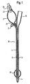
- FIG 1 shows a known pre-filled Foley catheter.
- the catheter 10 comprises a shaft 11 of latex rubber which defines a balloon inflation lumen 12 and a drainage lumen 13.
- the drainage lumen 13 extends from a distal drainage port 14 to a drainage bag coupling element 15 at the proximal end of the catheter.
- the inflation lumen 12 connects a chamber 20 at the distal end of the catheter, but proximal of the drainage port 14, with a reservoir bulb 21 at the proximal end of the device.
- both of the balloon 20 and bulb 21 are shown inflated, for the sake of clarity, but those skilled in the art will appreciate that the sterile water within the bulb 21 is not sufficient simultaneously to fill both the bulb and the balloon.
- the reality is that, when the bulb 21 is full, the balloon 20 is not yet inflated and, when the balloon 20 is fully inflated, the bulb 21 is deflated.
- the bulb 21 has a proximal end 22 and a distal end 23. At the proximal end 22 is a conventional one-way filler valve 24 with which those skilled in the art will already be familiar. At the distal neck 23 of the bulb 21, there is a conventional external clip E to clamp together the walls of the lumen 12.
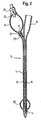
- FIG 2 the catheter shown in this drawing figure is identical to that of the Figure 1 catheter, except that the external clip E has been replaced, in accordance with the invention, by a plug 25 which is a friction fit inside the lumen 12, the plug 25 being introduced distally into the lumen 12 through the interior of the bulb 21 and, in so doing, elastically deforming the material of the shaft 11 of the catheter 10.
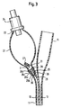
- Figure 3 shows in more detail the construction of this control device.
- control device can be seen to be made up of a tapered plug portion 26 and a solid stem portion 27 which occludes the proximal end 28 of a bore 29 which extends completely through the plug portion 26, as far as its distal end 30.
- the solid stem 27 is integral with the plug portion 26, but joined to it by a narrow and weak circle 31 of material around the proximal end 28 of the bore 29.
- the circle 31 constitutes a parting line.
- the tapered portion 26 is itself made up of adjacent more or less frusto-conical portions.
- the larger frusto-conical portion 26a has a relatively gentle taper along the plug axis, and the smaller frusto-conical portion 26b has a relatively faster steeper taper, together giving the plug a rounded bullet nose to be advanced along the lumen to the desire location.
- the length of the large diameter cylindrical portion 26d is preferably smaller than its radius, thereby enhancing lumen sealing around this portion of the plug.
- the length of the plug annulus is preferably greater than its maximum diameter, which helps to keep the plug pointing in the axial direction as it is pushed from behind to advance along the lumen.
- the control device is formed from synthetic polymeric material which is selected so that manual manipulation of the solid stem 27 relative to the plug portion 26 is quite sufficient to tear the polymer material at a point on the circumference of the weak circle 31, thereby allowing the stem 27 to rotate relative to the plug portion 26, with further tearing of the material around the circle 31 putting in fluid communication the bulb 21 surrounding the stem 27 with the bore 29 through the length of the plug portion 26.
- the stem 27 may lie in the lumen 12 spaced from the bulb, if the lumen is susceptible enough to external manipulation and bending to permit the stem 27 to be snapped away from the annulus 26.
- the stem portion 27 has a length of 10 and a diameter of 2.25;
- the plug portion has a length of 9 and a bore diameter of 2;
- the frusto-conical outer diameter range is from 5.5.
- the bulb can be water-proofed (as is known) for example by dipping in Saran® a polyvinylidene chloride coating composition. Otherwise it could be water-proofed by, e.g. dipping or spraying it with silicone, neoprene rubber, butyl rubber or hydrophobic polyurethane. Those skilled in the art will be aware of such procedures and practices.
- One suitable polymer material for the plug device is polyvinylchloride.
- PVC polyvinylchloride
- High impact polystyrene is another possibility.
- a polyester material such as polybutyleneterephthalate may be worthy of consideration.
- Styreneacrylonitrile is another polymer of particular interest.
- the selection of polymers for medical applications is a field in which there is considerable experience. Some special factors apply, for example, gamma ray sterilisation is usual, and the polymer must obviously be able to withstand all production process steps, including sterilisation, as well as being stable enough to survive the required shelf life period in the environment in which it finds itself. Resistance to solvents, possibly acetone, may be another significant factor. Putting the bulb interior in communication with the tube should not result in any loose fragments of the control device, especially not any transport of such fragments to the fluid acceptor. Accordingly, the preferred failure mode between stem portion 27 and plug portion 26 is tearing.
- the presently preferred embodiment involves a circle of weakness, and parting of the polymer material around the weakness circle 31, nevertheless it is contemplated that alternative embodiments, not presently preferred, might in the end prove more attractive, in which, for example, the stem portion 27 is not integral with the plug portion 26 but, rather, is a separate piece which is friction fitted with the proximal end 28 of the bore 29. If this were the case, then it might be appropriate to provide stepped or tapered portions of the proximal end of the bore 29 or the distal end of the stem 27.
- the present invention arose out of a consideration of how to improve a specific product, the pre-filled Foley catheter, nevertheless the concept of the invention might be applicable elsewhere.
- the interaction of a plug stopper and a distended elastomeric reservoir of sterile fluid could be useful whenever there is need for a supply of sterile fluid from a bulb.
- the plug remains intact, the fluid is safe and sterile within the bulb, and resistant to damage or decay but, upon a simple manipulation of the stem of the plug, a supply of sterile fluid is available, from the bulb, in whatever quantities and rate of flow are selected by the user, by varying the squeezing and manipulation of the elastomeric bulb.
- One way of providing the sleeve is to use stretchy material, pre-formed as a sleeve.
- the lumen 11 could be advanced through the sleeve, and then the sleeve restrained while the distal parts of the catheter are pulled through the sleeve, until the sleeve is stretched by the structures at the proximal end of the catheter and ends up stretched over the bulb 21 and bag connector 15, as shown in figure 4.
- shrink wrap material which is 50 ⁇ m thick oriented polystyrene material.
- Such material somewhat thinner, say 40 ⁇ m thick, is also seen as likely to be suitable and useful.
- shrink wrap sleeving which includes a tear strip or tab incorporated along its length. In the particular embodiment favoured at present by applicant, this tear tab has a width of 10 mm.
- Shrink wrap sleeving of the description immediately above, is available from Decorative Sleeves Ltd, Hardwick Industrial Estate, Kings Lynn, Norfolk, England.
- tear tab is not essential, and although the precise location of the tear tab relative to the drain coupling 15 and fluid bulb 21 is not critically important, it is presently preferred to locate the tear strip to lie over the surface of the bulb 21, diametrically opposite from the location of the drain coupling 15.
- heat shrinkage of the shrink wrap sleeving in a length which extends distally beyond the sealing annulus of the fluid control device 25, and proximally beyond the sealing annulus of the filler valve 24, is sufficient to place a more or less fluid-impervious coating over the bulb 21, whether the bag coupling 15 is inside or outside the shrink wrap sleeve.
- Applicant uses a vertically arranged heat shrink tunnel.
- the shaft 11 of the catheter is advanced through the sleeve prior to shrinking, so that the 90 mm length of the shrink sleeve lies over the catheter bulb 21 in the axial position shown in Figure 4 or Figure 5, and then the catheter, with the sleeve in place, is placed between two vertical conveyor belts of the heat shrink tunnel, with the proximal end of the catheter uppermost.
- the conveyor belts advance the catheter downwardly through the vertically arranged heat shrink tunnel and, as the proximal end of the catheter passes through the tunnel, the heat within the tunnel will cause the sleeving to shrink around the catheter bulb 21.
- the catheter is taken from the conveyors, again to be subjected to a manual quality check before being placed into a transport box for further processing.
- FIG 6 shows schematically the presently favoured method which applicant uses to insert the fluid control device 25 into the lumen of the catheter.
- a plurality of long flexible fingers 50 themselves mounted at their proximal ends to a finger ring 52, are introduced into the open end 22 of the catheter lumen which is to become the elastomeric bulb 21. Radially outward movement of the fingers 50 allows the plug 25 to be advanced axially past the open end 22 of the lumen, and beyond the part of the lumen 21 which becomes the bulb, until the plug 25 reaches the part 23 of the lumen which will become the distal neck of the bulb 21.
- the lumen narrows down, over the length of a neck-in section R4 to the diameter of the lumen in the shaft, which here is 0.8 mm.
- This advancement of the plug 25 along the lumen 12 is accomplished by an engagement of a female end 54 of an engagement rod 56 arranged on the axis of the plug insertion apparatus.
- the stem 27 of the plug 25 is received within the bore 58 of the female engagement portion 54 of the injector rod 56.
- the injector rod 56 is pneumatically operated.
- the rod 56 advances the plug 25 to the position shown in Figure 7, in which it is snugly and co-operatingly abutting the neck-in section R4 of the lumen.
- the fingers 50 retract to their initial disposition, enabling the open end 22 of the lumen 12 easily to be withdrawn from the fingers.
- the latex lumen wall is opaque, but because the prominent ring 26d of the large diameter cylindrical portion of the plug 25 distorts the latex lumen wall, as can be seen in Figures 2, 3, 4 and 5, the operative can check that the plug 25 is in the desired location. It will be noted that the stem 27 projects proximally into the void within the bulb 21. After this check, the partially manufactured catheter can be placed in a transport box, for onward transport and further processing.
- the invention enables improvements to be made in the manufacture, storage and handling of medical devices such as Foley catheters. These improvements are appreciated not only by manufacturers and users of these devices but also, in large measure, by those who manipulate the medical devices for industrial users.
- the subject matter of this invention is defined by features which are technical, and the invention delivers useful technical effects.
Description
- A pre-filled Foley catheter can be regarded as one example of a medical device with a proximal end and a distal end, an elastomeric bulb at the proximal end for storing fluid under pressure and a fluid acceptor at the distal end and a lumen connecting the bulb and the acceptor for flow of fluid from the bulb to the acceptor when the device is used, and including a control device at the proximal end of the lumen to prevent said fluid flow until said flow is desired. It is in this class of medical devices that the present invention is to be found.
- The Foley catheter is a catheter device usually made out of elastomeric material, which is for urine drainage and which is installed with its distal end in the bladder of the patient. When the distal end reaches the bladder, sterile water is caused to flow along a lumen from the proximal to the distal end of the catheter, there to fill a balloon surrounding the lumen and defined by the elastomeric wall of the catheter. This balloon retains the distal end of the catheter in the bladder and allows a second lumen in the catheter shaft, open to the bladder at the distal end of the shaft, to drain urine from the bladder to the proximal end of the catheter.
- In a so-called pro-filled Foley catheter, the device -comes complete with a reservoir of sterile water in the proximal end of the device, and a clip over the shaft of the catheter at its proximal end, which clip prevents the sterile water from flowing from the distended reservoir bulb along the lumen to the distal end of the catheter. The person placing the catheter is required to hold the catheter in the desired disposition relative to the body of the patient, and then remove the clip and squeeze the reservoir bulb, in order to inflate the balloon. See US-A-3602226 for a disclosure of such an external valve. See US-A-3275001 and US-A-3675658 for disclosures of using a plug inside the lumen instead of an external clip.
- Achievement of a satisfactory shelf-life for pre-filled Foley catheters has proved to be a challenge. Common elastomeric material, such as latex, is not entirely impermeable to the passage of water. Accordingly, the water in the distended bulb reservoir of elastomeric material can escape through the wall, given enough time. In order to achieve a satisfactory shelf-life (18 to 24 months) it has been proposed to cover the outside of the reservoir bulb with a coating of material more resistant to passage of water than latex. Nevertheless, residual problems remain. For a discussion, see US-A-3602226.
- One such problem is that the coating tends to crack. This reduces the resistance to escape of water and can adversely affect appearance. Another problem is to achieve satisfactory continuity of the coating around the clip at the distal end of the bulb, and the customary filler valve at the proximal end of the bulb. Even then, there is potential for water to escape from the bulb by flowing lengthways along the elastomeric material of the wall of the bulb, until it has passed the distal and proximal ends of the waterproof coating material.
- The thickness of latex catheters made by a conventional dipping process is always liable to vary, and this variation can prejudice the goal of reliable sealing with an external moulded clip. With a conventional U-shaped one-piece clip, and latex walls of uncertain thickness, there is some potential for the clip to damage the latex lumen wall.
- Attention is invited, to the disclosure of EP-A-177 859. A pivoting frangible valve for blood bags is disclosed. The valve is opened by external manipulation of the valve, by breaking a portion of the valve at a weakened portion of the valve itself.
- The invention is defined in claim 1 below. The dependent claims are directed to optimal and preferred features of the invention.
- With the invention, it is possible to achieve greater certainty, during the manufacture of pre-filled Foley catheters, that the catheter will deliver a satisfactory shelf life.
- With the present invention it is possible to provide a pre-filled catheter which lends itself to easy actuation, with a single manipulation (like removal of the conventional clip) being sufficient to achieve the result that all fluid in the reservoir flows to the distal end balloon cavity.
- With the invention one can improve the design of the catheter so that its manufacture is streamlined, its packaging and storage made more compact and reliable, and its appearance made more attractive.
- By resorting to a plug with a parting line, a number of unforeseen advantages emerge, as follows.
- Once the plug is parted, there is no need for the person installing the catheter to manipulate any longer the plug or lumen.
- The stress distribution in the wall of the bulb at the neck at its distal end is much more uniform with a plug than with the customary clip, An enhanced ability to predict patterns of stress and strain at the balloon neck should in turn allow better waterproofing in the distal neck region.
- Provision of a parting line avoids the need to disturb the interface between plug and lumen. This is especially advantageous with latex lumens, or other lumens created by dipping, in which the wall thickness varies, because actuation of the control device need not involve any surface in contact with the lumen wall. Where the lumen wall thickness varies, so will the elastic performance, and when the elastic performance varies, there will be unpredictability in the manipulation of any surfaces constrained elastically by the lumen wall surface.
- Conventionally, a Foley catheter of latex is moulded with a narrow lumen (say 0.8 mm diameter) and a proximal bulb inner diameter much larger. Thus, with the invention, the distal neck of the bulb cavity can be molded to correspond in shape with the distal end of the plug. These complementary surfaces prevent excessive advance of the plug distally beyond the bulb neck.
- Stabilisation of the interface between the lumen wall and the surfaces of the control device makes it easier to render the bulb fluid-tight in this interface zone. The medical device is much easier to pack and to handle in the terminal stages of manufacture because it lacks the bulk of an external clip.
- Conventional external clips become separated from the conventional pre-filled Foley catheter, once the catheter has been installed, and one then has the task of disposing of the loose clip. With the device of the invention, the component parts of the control device are retained within the bulb.
- One-handed operation of the valve requires less manual dexterity than with an external clip which has to be removed. Snapping of the plug into two pieces provides a tactile signal that the fluid passage has been opened up. With opaque lumen material, such as latex, the plug cannot be seen, so such a tactile signal is especially valuable with opaque materials.
- Prior to the making of this invention, applicant experimented with waterproof coatings on the inside of the elastomeric bulb. These attempts were abandoned because it was found that the material of the coating tended to block the lumen at the distal end of the bulb. However, with the present invention, there is fresh potential for waterproofing the inside of the bulb, because the placement of the plug in the distal neck of the bulb, before any fluid -impervious coating is introduced onto the inside surface of the bulb wall, will prevent the coating material from blocking the lumen at the distal end of the bulb. With appropriate design of the plug, a coating of proofing material on the external surface of the plug ought not to have any adverse effect on the operation of the control device.
- In another embodiment, it is envisaged that the plug device might carry with it a skirt or cylinder of waterproof material, to serve as the fluid-resistant wall of the bulb, or an inner waterproof surface coating of the wall of the bulb, the skirt or cylinder being gathered at the proximal end of the bulb, and fitted around the customary bulb filler valve. Cakes are decorated using an icing sugar mixture which is extruded through an icing nozzle, itself set in the neck of an icing bag. The other end of the bag is held closed by the hand of the user. The contemplated arrangement of plug and skirt might resemble an arrangement of icing nozzle and icing bag, with the filler valve closing the end of the skirt remote from the plug.
- The control of flow of fluid in a lumen, using a device in the lumen which is separable into two parts in order to allow fluid flow, is not in itself new. Such an arrangement is disclosed in, for example, GB-A-1513482 and US-A-4007738 published February 15, 1977. It is to be noted, however, that the proposal of the present invention allows the control device to be placed such that it extends proximally into the interior of the bulb. This provides more room for displacement of one part of the control device relative to the other, and for eliminating elastic stresses in a lumen wall which might otherwise act to bring the two displaced parts of the control device back into their original sealing disposition relative to each other. Depending on the materials used and the dimensions of the plug and lumen walls, locating the control device partly within the bulb may assist in delivering many of the attractive technical effects of the present invention.
- In one embodiment, the present invention provides a medical device which is a drainage catheter having first and second lumens, with the first lumen serving as a drainage lumen and having a fluid inflow port at its distal end and a fluid drain coupling at its proximal end. The second lumen serves to convey inflating fluid from a fluid supply element at the proximal end of the device to a fluid acceptor balloon at the distal end. The fluid supply element and fluid drain coupling are arranged side by side at the proximal end of the coupling, and the device is characterised by a sleeve which extends around both the fluid drain coupling and the fluid supply element.
- Normally, the fluid supply element will be an elastomeric bulb which is destined to be inflated with the inflating fluid. In that case, the sleeve would be of a material which is more impervious to the inflating fluid than is the elastomeric material of the bulb, so that the presence of the sleeve has the effect of slowing the rate of loss of fluid radially outwardly from the bulb through the wall thickness of the bulb.
- Although this is the normal situation, it is envisaged that the provision of a sleeve, around both the fluid drain coupling and the fluid supply element could have other advantages independent of reducing fluid loss during storage of a pre-filled device. For example, in the case where the device is made of material which does not readily accept printed text, or in a case where it is desired that there should be no printed text on the device as such, the sleeve material could be selected as suitable for use as a printing substrate, and could receive printed matter which serves to inform those handling the device, until such time as the device is put into use, at which point the sleeve would be removed.
- It is particularly envisaged that the technical feature of a sleeve is used in combination with the technical feature of a lumen plug which parts into two pieces, characteristic of the invention. In particular, a urinary drainage catheter, such as a Foley catheter, which incorporates e reservoir pre-filled with liquid to inflate the distal bulb of the catheter, and which is made, as conventionally, with latex rubber material, benefits from an enhanced shelf life both by the provision of a sleeve around the reservoir bulb at the proximal end of the catheter, and the provision of a plug instead of a conventional external lumen clip, because the sleeve over the bulb works more effectively when there is no clip on the external surface of the catheter adjacent the reservoir bulb. This is because it is easier to arrange the sleeve for full effectiveness when the surface it covers is without discontinuities, and when the sleeve is not subject to localised stresses caused by the external clip.
- In this way, the sleeve and plug work together to enhance the shelf life of the device.
- In this connection, inclusion of the fluid drain coupling alongside the fluid supply element inside the sleeve will not appreciably reduce the effectiveness of the sleeve in slowing down the rate of loss of fluid through the wall of the reservoir bulb. This is because both elements can be made with surface topographies made up of gentle curves and out of relatively soft materials which therefore deform relatively easily to conform to the embrace of a sleeve applied using shrink wrapping techniques. However, placing the sleeve around both the fluid drain coupling and the fluid supply element can deliver the technical effect that the device is packed in a more compact and orderly way, which facilitates further manufacturing processing and packaging of the device, and improves the visual attractiveness of the device to those who purchase and use it. It also provides a packaging over the fluid drain coupling (which in present devices is not sleeved) and a vehicle for carrying printed matter.
- The invention is particularly applicable to medical devices made of latex rubber, especially urine drainage catheters made of latex rubber. However, the invention will also be useful with devices made of other materials. One of these may be silicone rubber, an alternative material for urine drainage catheters.
- Normally, the fluid received at the distal end of the catheter will be water, that is, sterile water, but the invention is not restricted to fluids which are liquids. Fluids which are gases may also be of interest.
- The plug control device is conveniently formed as an annulus of material with a proximal end face and a distal end face and a bore extending between the two end faces. Coaxial with the annulus is a stem, blocking the bore in the annulus, until the plug is parted into two separate parts, these two separate parts being the annulus and the stem. Conveniently, the plug is formed of synthetic polymeric material, injection moulded as a single component, with a circle of weakness, constituting the parting line, between the annulus and the stem, at one end of the bore through the annulus. However, it can also be envisaged that the plug is formed of two components, the annulus and the stem, put together as the plug is installed in the lumen, and parted into the respective annulus and stem components, along the parting line where the two components abut one another; when the stem is manipulated from outside the device. In such a case, the stem might be friction fitted within the bore of the annulus.
- Normally the stem is cylindrical and has a diameter not more than about half that of the plug at its widest point. Advantageously, the stem is not more than one third the plug diameter. In one example, the stem is 2.25 mm diameter and the plug at its widest is 7.5 mm in diameter. This leaves plenty of room around the stem to engage the stem with an injector rod to position the plug in the lumen.
- Normally, the plug is advanced into the lumen from the proximal end of the lumen with its stem directed rearwardly. Normally, the open proximal end of the lumen is closed by a filler valve, and the plug is spaced some way from the filler valve, distally along the lumen. The lumen length between the filler valve and the plug contains the cavity for storing fluid under pressure, that is to say, the fluid supply element and elastomeric bulb of preferred embodiments of the present invention. Fluid is introduced through the filler valve into the lumen cavity between the filler valve and the plug, to inflate the elastomeric bulb between the valve and the plug. The valve is a check valve (not unlike one on a bicycle tyre) which resists reverse flow of the fluid in the bulb. In these respects, the reader will be informed by conventional practice in the technical field of urine drainage catheters, particularly Foley catheters. Variations of construction of the filler valve are not in themselves an aspect of the subject matter of the present invention.
- For a better understanding of the present invention, and to show more clearly how the same made be carried into effect, reference will now be made, to the accompanying drawings, in which:
- Figure 1 is a longitudinal diametral section through a Foley catheter which is within the state of the art;
- Figure 2 is a longitudinal diametral section through a Foley catheter in accordance with the present invention; and
- Figure 3 is a longitudinal diametral section through the proximal end of the Figure 2 catheter, showing the plug parted into two parts;
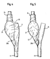
- Figure 4 is a longitudinal diametral section of a catheter in accordance with Figure 2, showing a sleeve extending around both the fluid drain coupling and the fluid supply element;
- Figure 5 is a longitudinal section, similar to that of Figure 4, but showing a sleeve which extends only around the fluid supply element, and not around the fluid drain coupling;
- Figure 6 is a longitudinal section through apparatus for placing the plug inside the lumen of the Foley catheter; and
- Figure 7 is a section like Figure 6, but showing the plug after placement in the lumen.
- Figure 1 shows a known pre-filled Foley catheter. The
catheter 10 comprises ashaft 11 of latex rubber which defines aballoon inflation lumen 12 and adrainage lumen 13. Thedrainage lumen 13 extends from adistal drainage port 14 to a drainagebag coupling element 15 at the proximal end of the catheter. Theinflation lumen 12 connects achamber 20 at the distal end of the catheter, but proximal of thedrainage port 14, with areservoir bulb 21 at the proximal end of the device. In Figure 1, both of theballoon 20 andbulb 21 are shown inflated, for the sake of clarity, but those skilled in the art will appreciate that the sterile water within thebulb 21 is not sufficient simultaneously to fill both the bulb and the balloon. The reality is that, when thebulb 21 is full, theballoon 20 is not yet inflated and, when theballoon 20 is fully inflated, thebulb 21 is deflated. - The
bulb 21 has aproximal end 22 and adistal end 23. At theproximal end 22 is a conventional one-way filler valve 24 with which those skilled in the art will already be familiar. At thedistal neck 23 of thebulb 21, there is a conventional external clip E to clamp together the walls of thelumen 12. - Turning to Figure 2, the catheter shown in this drawing figure is identical to that of the Figure 1 catheter, except that the external clip E has been replaced, in accordance with the invention, by a
plug 25 which is a friction fit inside thelumen 12, theplug 25 being introduced distally into thelumen 12 through the interior of thebulb 21 and, in so doing, elastically deforming the material of theshaft 11 of thecatheter 10. Figure 3 shows in more detail the construction of this control device. - In Figure 3 the control device can be seen to be made up of a tapered
plug portion 26 and asolid stem portion 27 which occludes theproximal end 28 of abore 29 which extends completely through theplug portion 26, as far as itsdistal end 30. Thesolid stem 27 is integral with theplug portion 26, but joined to it by a narrow andweak circle 31 of material around theproximal end 28 of thebore 29. Thecircle 31 constitutes a parting line. - The tapered
portion 26 is itself made up of adjacent more or less frusto-conical portions. The larger frusto-conical portion 26a has a relatively gentle taper along the plug axis, and the smaller frusto-conical portion 26b has a relatively faster steeper taper, together giving the plug a rounded bullet nose to be advanced along the lumen to the desire location. There is a step 26c between the tapered portion of the plug and itscylindrical portion 26d of largest diameter. - The length of the large diameter
cylindrical portion 26d is preferably smaller than its radius, thereby enhancing lumen sealing around this portion of the plug. The length of the plug annulus is preferably greater than its maximum diameter, which helps to keep the plug pointing in the axial direction as it is pushed from behind to advance along the lumen. - The control device is formed from synthetic polymeric material which is selected so that manual manipulation of the
solid stem 27 relative to theplug portion 26 is quite sufficient to tear the polymer material at a point on the circumference of theweak circle 31, thereby allowing thestem 27 to rotate relative to theplug portion 26, with further tearing of the material around thecircle 31 putting in fluid communication thebulb 21 surrounding thestem 27 with thebore 29 through the length of theplug portion 26. - Because of the softness of the bulb, and the open space between the wall surfaces of the
bulb 21 surrounding thestem 27, there is great scope for manual manipulation of the bulb, from outside it, to achieve a large angle of rotation of thestem 27 relative to theplug portion 26, with consequent great certainty of putting thebulb 21 in communication with thebore 29. Nevertheless, thestem 27 may lie in thelumen 12 spaced from the bulb, if the lumen is susceptible enough to external manipulation and bending to permit thestem 27 to be snapped away from theannulus 26. - Those skilled in the art will be familiar with the -conventional dimensions of a pre-filled Foley catheter. Of course, many of these are determined by the dimensions of the associated parts of the human body. The researches of the present applicant, as to what are the preferred dimensions of the plug control device, have resulted in a proposal that the control device should be constructed in accordance with the following scheme of dimensions (all in mm): the
stem portion 27 has a length of 10 and a diameter of 2.25;. the plug portion has a length of 9 and a bore diameter of 2; the frusto-conical outer diameter range is from 5.5. to 4.3; there is a transition zone from the proximal end of the 2 mm axial bore of the plug portion, to the 2.25 mm diameter circle on the proximal end face of the plug portion, which extends distally from the proximal end face over a distance of 0.625 mm. - The bulb can be water-proofed (as is known) for example by dipping in Saran® a polyvinylidene chloride coating composition. Otherwise it could be water-proofed by, e.g. dipping or spraying it with silicone, neoprene rubber, butyl rubber or hydrophobic polyurethane. Those skilled in the art will be aware of such procedures and practices.
- One suitable polymer material for the plug device is polyvinylchloride. However, there is currently prejudice against the use of PVC. High impact polystyrene is another possibility. A polyester material such as polybutyleneterephthalate may be worthy of consideration. Styreneacrylonitrile is another polymer of particular interest. The selection of polymers for medical applications is a field in which there is considerable experience. Some special factors apply, for example, gamma ray sterilisation is usual, and the polymer must obviously be able to withstand all production process steps, including sterilisation, as well as being stable enough to survive the required shelf life period in the environment in which it finds itself. Resistance to solvents, possibly acetone, may be another significant factor. Putting the bulb interior in communication with the tube should not result in any loose fragments of the control device, especially not any transport of such fragments to the fluid acceptor. Accordingly, the preferred failure mode between
stem portion 27 and plugportion 26 is tearing. - Although the presently preferred embodiment involves a circle of weakness, and parting of the polymer material around the
weakness circle 31, nevertheless it is contemplated that alternative embodiments, not presently preferred, might in the end prove more attractive, in which, for example, thestem portion 27 is not integral with theplug portion 26 but, rather, is a separate piece which is friction fitted with theproximal end 28 of thebore 29. If this were the case, then it might be appropriate to provide stepped or tapered portions of the proximal end of thebore 29 or the distal end of thestem 27. - Although the present invention arose out of a consideration of how to improve a specific product, the pre-filled Foley catheter, nevertheless the concept of the invention might be applicable elsewhere. In particular, the interaction of a plug stopper and a distended elastomeric reservoir of sterile fluid could be useful whenever there is need for a supply of sterile fluid from a bulb. Thus, it could be arranged that, while the plug remains intact, the fluid is safe and sterile within the bulb, and resistant to damage or decay but, upon a simple manipulation of the stem of the plug, a supply of sterile fluid is available, from the bulb, in whatever quantities and rate of flow are selected by the user, by varying the squeezing and manipulation of the elastomeric bulb.
- Moving on to drawing Figures 4 and 5, here are shown alternatives, in accordance with the second aspect of the present invention, to coating the fluid supply element at the proximal end of the device. Instead of dipping the proximal end in a coating liquid, the proximal end is surrounded by a sleeve. This sleeve can be like the
sleeve 40 of Figure 4, embracing both thebulb 21 and thecoupling element 15, or like thesleeve 42 of Figure 5, embracing only thebulb 21 and not thecoupling 15. - One way of providing the sleeve is to use stretchy material, pre-formed as a sleeve. The
lumen 11 could be advanced through the sleeve, and then the sleeve restrained while the distal parts of the catheter are pulled through the sleeve, until the sleeve is stretched by the structures at the proximal end of the catheter and ends up stretched over thebulb 21 andbag connector 15, as shown in figure 4. - However, it is presently preferred by Applicant to pre-form the sleeve from shrink wrap material, which is 50 µm thick oriented polystyrene material. Such material, somewhat thinner, say 40 µm thick, is also seen as likely to be suitable and useful. For the conventional Foley catheters which Applicant makes, it is appropriate to use a pre-formed tube which, when flat, has a width of 45 mm and which, for use in the present invention, is cut into lengths of 90 mm, this being long enough to extend over not only the
bulb 21 but also thefluid control device 25 and the distal end of thefiller valve 24, as shown in Figures 4 and 5. Preferred is shrink wrap sleeving which includes a tear strip or tab incorporated along its length. In the particular embodiment favoured at present by applicant, this tear tab has a width of 10 mm. - Shrink wrap sleeving, of the description immediately above, is available from Decorative Sleeves Ltd, Hardwick Industrial Estate, Kings Lynn, Norfolk, England.
- Although a tear tab is not essential, and although the precise location of the tear tab relative to the
drain coupling 15 andfluid bulb 21 is not critically important, it is presently preferred to locate the tear strip to lie over the surface of thebulb 21, diametrically opposite from the location of thedrain coupling 15. - Those skilled in the art will be familiar with techniques for printing on polystyrene film. Should it be desired, printed matter can be placed on the polystyrene tubing pre-form, before the sleeve is placed over the bulb of the catheter.
- As can be seen in Figures 4 and 5, heat shrinkage of the shrink wrap sleeving, in a length which extends distally beyond the sealing annulus of the
fluid control device 25, and proximally beyond the sealing annulus of thefiller valve 24, is sufficient to place a more or less fluid-impervious coating over thebulb 21, whether thebag coupling 15 is inside or outside the shrink wrap sleeve. - As the presently favoured method of placing the shrink wrap sleeve over the
catheter bulb 21, Applicant uses a vertically arranged heat shrink tunnel. Thus, theshaft 11 of the catheter is advanced through the sleeve prior to shrinking, so that the 90 mm length of the shrink sleeve lies over thecatheter bulb 21 in the axial position shown in Figure 4 or Figure 5, and then the catheter, with the sleeve in place, is placed between two vertical conveyor belts of the heat shrink tunnel, with the proximal end of the catheter uppermost. The conveyor belts advance the catheter downwardly through the vertically arranged heat shrink tunnel and, as the proximal end of the catheter passes through the tunnel, the heat within the tunnel will cause the sleeving to shrink around thecatheter bulb 21. - At the bottom end of the heat shrink tunnel, the catheter is taken from the conveyors, again to be subjected to a manual quality check before being placed into a transport box for further processing.
- Turning now to Figure 6, this shows schematically the presently favoured method which applicant uses to insert the
fluid control device 25 into the lumen of the catheter. A plurality of longflexible fingers 50, themselves mounted at their proximal ends to afinger ring 52, are introduced into theopen end 22 of the catheter lumen which is to become theelastomeric bulb 21. Radially outward movement of thefingers 50 allows theplug 25 to be advanced axially past theopen end 22 of the lumen, and beyond the part of thelumen 21 which becomes the bulb, until theplug 25 reaches thepart 23 of the lumen which will become the distal neck of thebulb 21. Here, the lumen narrows down, over the length of a neck-in section R4 to the diameter of the lumen in the shaft, which here is 0.8 mm. - This advancement of the
plug 25 along thelumen 12 is accomplished by an engagement of afemale end 54 of anengagement rod 56 arranged on the axis of the plug insertion apparatus. Thestem 27 of theplug 25 is received within thebore 58 of thefemale engagement portion 54 of theinjector rod 56. - Conveniently, the
injector rod 56 is pneumatically operated. In practice, it is convenient to provide the apparatus with a foot pedal actuator for theinjector rod 56, so that a human operative can arrange thelumen end 22,fingers 50 and plug 25 as desired, with delicate use of the fingers, and then achieve plug insertion in thelumen 12 using a movement of the foot to actuate the foot pedal. - The
rod 56 advances theplug 25 to the position shown in Figure 7, in which it is snugly and co-operatingly abutting the neck-in section R4 of the lumen. - Once the plug is inserted, and the
injector rod 56 retracted, thefingers 50 retract to their initial disposition, enabling theopen end 22 of thelumen 12 easily to be withdrawn from the fingers. The latex lumen wall is opaque, but because theprominent ring 26d of the large diameter cylindrical portion of theplug 25 distorts the latex lumen wall, as can be seen in Figures 2, 3, 4 and 5, the operative can check that theplug 25 is in the desired location. It will be noted that thestem 27 projects proximally into the void within thebulb 21. After this check, the partially manufactured catheter can be placed in a transport box, for onward transport and further processing. - The invention enables improvements to be made in the manufacture, storage and handling of medical devices such as Foley catheters. These improvements are appreciated not only by manufacturers and users of these devices but also, in large measure, by those who manipulate the medical devices for industrial users. The subject matter of this invention is defined by features which are technical, and the invention delivers useful technical effects.
Claims (30)
- A medical device (10) with a proximal end (22) and a distal end (23), an elastomeric bulb (21) at the proximal end for storing fluid under pressure, a fluid acceptor (20) at the distal end and a lumen (12) connecting the bulb and the acceptor for flow of fluid from the bulb to the acceptor when the device is used, and including a control device (25) at the proximal end of the lumen to prevent said flow until said flow is desired
said control device (25) comprises a plug (25) which blocks the lumen at its proximal end and includes a parting line, which enables the plug to be parted into two separate parts, by manual manipulation from outside the lumen, such parting having the effect of opening up fluid communication along the lumen from the elastomeric bulb (21) to the fluid acceptor (20) to fully fill the acceptor, and characterised in that
wherein the plug comprises a co-axial stem (27) and annular part with a diameter at least twice that of the stem (27), which meet at said parting line wherein the annular part comprises a tapering portion displaying a small end and a large end, the small end being remote from the stem, wherein the annular part comprises a cylindrical portion, wherein the cylindrical portion lies between the tapering portion and the stem, in the axial direction of the plug, wherein the diameter of the cylindrical portion is greater than that of the large end of the tapering portion, including a step (26c) between the large end of the tapering portion and the cylindrical portion. - Device as claimed in claim 1 wherein the bulb (21) is coated with a substance to inhibit the passage of the fluid through the wall thickness of the bulb.
- Device as claimed in claim 2 wherein the coating is on the outside of the bulb wall thickness.
- Device as claimed in claim 2 wherein the coating is on the inside surface of the bulb wall.
- Device as claimed in claim 1 wherein the plug (26) carries a fluid-tight skirt membrane which extends proximally from the proximal end face of the plug.
- Device as claimed in any one of the preceding claims, wherein the acceptor is a balloon (20).
- Device as claimed in any one of the preceding claims wherein the medical device is a catheter (10).
- Device as claimed in claim 7 wherein the catheter is a drainage catheter.
- A medical device as claimed in claim 8 having first and second lumens extending therebetween, the first lumen serving as a drainage lumen and having a fluid inflow port at its distal end and a fluid drain coupling at its proximal end, the second lumen serving to convey inflating fluid from a fluid supply element (21) at its proximal end to a balloon (20) at its distal end which is said fluid acceptor, with the fluid supply element (21) and the fluid drain coupling arranged side by side at the proximal end of the lumen, and which further includes
a sleeve which extends around both the fluid drain coupling and the fluid supply element. - A device as claimed in claim 9, wherein the sleeve is of a material which is more impervious to said fluid than is the elastomeric material of said bulb (21) thereby to have the effect of slowing the rate of loss of fluid radially outwardly from the bulb (21) through the wall thickness of the bulb.
- Device as claimed in any one of the preceding claims, wherein the acceptor (20) is made of elastomer.
- Device as claimed in any one of the preceding claims and made of latex rubber.
- Device as claimed in any one of the preceding claims wherein the fluid is a liquid, and the fluid supply element (21) contains said fluid.
- Device as claimed in claim 13 wherein the fluid is water.
- Device as claimed in any one of the preceding claims, wherein the diameter of the annular part of the plug is at least three times that of the stem.
- Device as claimed in claim 15 wherein the annular part comprises an annulus (26) of material with a proximal end face (30) and a distal end face (28) and a bare (29) extending between the two end faces.
- Device as claimed in claim 15 or 16, wherein said stem (27) extends proximal of the annular part, coaxially therewith and has an outside diameter substantially less than that of said annular part (26).
- Device as claimed in claim 17 wherein the stem is friction fitted within the bore (29) of the annular part.
- Device as claimed in claim 17 wherein the stem (27) is integral with the annular part and joined to it by a circle of weakness (31).
- Device as claimed in claim 19 wherein the annular part and stem are together formed as only one piece of molded polymer material.
- Device as claimed in any one of claims 15 to 20, wherein the axial length of the annular part is greater than its largest diameter.
- Device as claimed in any one of the preceding claims, wherein the length of the cylindrical portion is smaller than its radius.
- Device as claimed in any one of the preceding claims, in which the tapering portion comprises a frusto-conical or substantially frusto-conical portion which has a small end which is larger than the small end of the tapering portion.
- Device as claimed in any one of the preceding claims, in which the tapering portion comprises a frusto-conical or substantially frusto-conical portion which has a small end which constitutes the small end of the tapering portion.
- Device as claimed in claim 24, as dependent on claim 23, wherein the tapering portion comprises first and second frusto-conical or substantially frusto-conical portions, of different cone angle, such that the diameter of the tapering portion varies along the axis at a greater rate near the small end of the tapering portion than at the large end of the tapering portion.
- Device as claimed in any one of the preceding claims in which the stem is cylindrical.
- Device as claimed in any one of the preceding claims wherein the fluid supply element (21) has an open proximal end (22) closed by a filler valve (24).
- Device as claimed in any one of the preceding claims, and which is a urinary drainage catheter.
- Device as claimed in claim 28 wherein the catheter is a Foley catheter.
- Plug (25) for use as a flow control device in a medical device as claimed in any one of the preceding claims, said plug having an annular part and a stem (27) with a diameter not more than half that of the annular part, and with a parting line where the stem joins the annulus wherein the annular part comprises a tapering portion displaying a small end and a large end, the small end being remote from the stem, wherein the annular part comprises a cylindrical portion, wherein the cylindrical portion lies between the tapering portion and the stem, in the axial direction of the plug, wherein the diameter of the cylindrical portion is greater than that of the large end of the tapering portion, including a step (26c) between the large end of the tapering portion and the cylindrical portion.
Priority Applications (1)
| Application Number | Priority Date | Filing Date | Title |
|---|---|---|---|
| EP99931182A EP1089784B1 (en) | 1998-06-25 | 1999-06-25 | Medical device with elastomeric bulb |
Applications Claiming Priority (4)
| Application Number | Priority Date | Filing Date | Title |
|---|---|---|---|
| WOPCT/EP98/03892 | 1998-06-25 | ||
| EP9803892 | 1998-06-25 | ||
| EP99931182A EP1089784B1 (en) | 1998-06-25 | 1999-06-25 | Medical device with elastomeric bulb |
| PCT/EP1999/004421 WO1999066976A2 (en) | 1998-06-25 | 1999-06-25 | Medical device with elastomeric bulb |
Publications (2)
| Publication Number | Publication Date |
|---|---|
| EP1089784A2 EP1089784A2 (en) | 2001-04-11 |
| EP1089784B1 true EP1089784B1 (en) | 2006-08-02 |
Family
ID=8166985
Family Applications (1)
| Application Number | Title | Priority Date | Filing Date |
|---|---|---|---|
| EP99931182A Expired - Lifetime EP1089784B1 (en) | 1998-06-25 | 1999-06-25 | Medical device with elastomeric bulb |
Country Status (7)
| Country | Link |
|---|---|
| US (4) | US6979313B1 (en) |
| EP (1) | EP1089784B1 (en) |
| JP (1) | JP2002518140A (en) |
| CA (1) | CA2335957A1 (en) |
| DE (1) | DE69932616T2 (en) |
| ES (1) | ES2270604T3 (en) |
| WO (1) | WO1999066976A2 (en) |
Families Citing this family (24)
| Publication number | Priority date | Publication date | Assignee | Title |
|---|---|---|---|---|
| EP1089784B1 (en) * | 1998-06-25 | 2006-08-02 | C.R. Bard, Inc. | Medical device with elastomeric bulb |
| EP1551355B1 (en) * | 2002-10-15 | 2013-06-19 | GO Medical Industries Pty Ltd | A device for delivering fluid to the bladder |
| US20060161102A1 (en) * | 2005-01-18 | 2006-07-20 | Newcomb Kenneth R | Controlled failure balloon catheter assemblies |
| US20070015109A1 (en) * | 2005-07-14 | 2007-01-18 | Ryoji Yamaguchi | Jaw denture |
| WO2007022050A1 (en) | 2005-08-12 | 2007-02-22 | Vance Products Incorporated, D/B/A/ Cook Urological Incorporated | Drainage catheter with extended inflation lumen |
| WO2007085971A2 (en) * | 2006-01-24 | 2007-08-02 | C. R. Bard, Inc. | Water barrier for medical device |
| US8684175B2 (en) * | 2006-09-22 | 2014-04-01 | Covidien Lp | Method for shipping and protecting an endotracheal tube with an inflated cuff |
| US8562557B2 (en) * | 2007-05-25 | 2013-10-22 | Medical Components, Inc. | Small diameter dual lumen catheter |
| WO2009046176A1 (en) * | 2007-10-02 | 2009-04-09 | C. R. Bard, Inc. | Drainage catheter with one-way valve |
| AU2008347296A1 (en) * | 2008-01-04 | 2009-07-16 | C.R. Bard, Inc | Synthetic polyisoprene foley catheter |
| CA2668792C (en) | 2008-06-30 | 2017-08-01 | Tyco Healthcare Group Lp | Valve assembly including a dissolvable valve member |
| WO2010002914A1 (en) * | 2008-06-30 | 2010-01-07 | C.R. Bard, Inc. | Polyurethane/polysoprene blend catheter |
| US7998113B2 (en) * | 2008-09-30 | 2011-08-16 | Tyco Healthcare Group Lp | Medical device having prefilled balloon |
| US8518020B2 (en) | 2010-08-23 | 2013-08-27 | Mayo Foundation For Medical Education And Research | Safety urinary catheter |
| NO333062B1 (en) | 2011-01-13 | 2013-02-25 | Geir Hoelsaeter | Tool for simplifying attachment of hose to nipple |
| BR122021000786B1 (en) | 2011-08-17 | 2021-05-25 | Surgical Stabilization Technologies Inc | Trocar support apparatus for use with a trocar separate from the apparatus to hold the trocar in a fixed position on a patient's body wall |
| EP3092025B1 (en) | 2014-01-09 | 2020-03-18 | Hollister Incorporated | Package having integral tab with finger hole opening feature |
| EP3750495B1 (en) | 2015-11-17 | 2023-08-30 | Surgical Stabilization Technologies Inc. | Trocar support |
| WO2017180640A1 (en) | 2016-04-12 | 2017-10-19 | Safe Medical Design, Inc. | Safe urinary catheter and manufacturing method |
| US20180344973A1 (en) * | 2017-06-06 | 2018-12-06 | Jane ALLEN | Catheter with dedicated flushing port |
| US10835688B2 (en) * | 2017-08-01 | 2020-11-17 | Tejash Patel | Enhanced needle |
| MX2021003191A (en) * | 2018-09-26 | 2021-05-27 | Nxstage Medical Inc | Configurable fluid channel sealing devices and methods. |
| IT201800010798A1 (en) * | 2018-12-04 | 2020-06-04 | Sergiani Bruno | URINARY CATHETER |
| GB202006055D0 (en) * | 2020-04-24 | 2020-06-10 | Convatec Ltd | A wetting mechanism for a catheter |
Family Cites Families (33)
| Publication number | Priority date | Publication date | Assignee | Title |
|---|---|---|---|---|
| DE3100442C1 (en) | 1962-05-08 | 1982-09-30 | Dr. Eduard Fresenius, Chemisch-pharmazeutische Industrie KG, 6380 Bad Homburg | Adapter piece for plastic cannulas and vein catheters |
| US3275001A (en) * | 1962-05-22 | 1966-09-27 | Kendall & Co | Self-inflatable catheter |
| US3190291A (en) * | 1962-10-08 | 1965-06-22 | Frederic E B Foley | Self-inflating bag catheter |
| US3602226A (en) * | 1965-11-19 | 1971-08-31 | Kendall & Co | Self-inflating catheter with means to prevent loss of inflation fluid |
| US3599620A (en) | 1969-08-18 | 1971-08-17 | Kendall & Co | Resilient reservoir assembly |
| US3675658A (en) * | 1970-09-03 | 1972-07-11 | Kendall & Co | Catheter with valved fluid reservoir |
| US4018231A (en) * | 1974-01-24 | 1977-04-19 | Airco, Inc. | Disposable balloon type catheter |
| JPS5240621Y2 (en) | 1974-07-31 | 1977-09-13 | ||
| US4116201A (en) * | 1976-12-20 | 1978-09-26 | The Kendall Company | Catheter with inflation control device |
| US4140127A (en) * | 1977-04-08 | 1979-02-20 | The Kendall Company | Catheter assembly |
| US4181140A (en) | 1978-02-10 | 1980-01-01 | Baxter Travenol Laboratories, Inc. | Frangible resealable closure for a flexible tube having hold open means |
| JPS5448996A (en) | 1977-07-25 | 1979-04-17 | Baxter Travenol Lab | Weak stopping tool* which can again be sealed* of flexible tube |
| US4248236A (en) | 1978-12-26 | 1981-02-03 | Linder Gerald S | Packaged medical appliance |
| US4340049A (en) | 1979-10-18 | 1982-07-20 | Baxter Travenol Laboratories, Inc. | Breakaway valve |
| US4462430A (en) * | 1982-09-20 | 1984-07-31 | Anthony Leonard R | Pipe plugging device |
| DE3324699C1 (en) | 1983-07-08 | 1984-12-06 | B. Braun Melsungen Ag, 3508 Melsungen | Valve device |
| DE3330148A1 (en) | 1983-08-20 | 1985-03-07 | Deutsche Präzisions-Ventil GmbH, 6234 Hattersheim | Nonreturn valve for medical purposes, especially for balloon-tipped catheters |
| US4586928A (en) * | 1984-10-09 | 1986-05-06 | Miles Laboratories, Inc. | Pivoting frangible valve for plastic bags |
| DE3677535D1 (en) | 1985-02-28 | 1991-03-28 | Medtronic Inc | INCONTINENCE CONTROL DEVICE. |
| US5181913A (en) * | 1987-03-09 | 1993-01-26 | Prn Services, Inc. | Catheter with check valve and rolled sheath |
| JPS6420858A (en) | 1987-07-16 | 1989-01-24 | Terumo Corp | Tube body equipped with plug body separable by breakage |
| DE3837779A1 (en) | 1987-11-12 | 1989-05-24 | Ernst Peter Prof Dr M Strecker | CATHETER SYSTEM WITH INFUSION CHAMBER |
| DE3915251A1 (en) | 1989-05-10 | 1990-11-22 | Annemarie Schloegl Ges M B H | IMPLANTABLE DEVICE FOR DISPENSING DISPOSAL OF MEDICINES IN HUMAN BODIES |
| DE3927001A1 (en) | 1989-08-16 | 1991-02-21 | Lucien C Dr Med Olivier | CATHETER SYSTEM |
| US5014407A (en) | 1989-09-28 | 1991-05-14 | Boughten Larry R | Tube expanding device |
| DE4116474C2 (en) | 1991-05-21 | 1994-10-06 | Spang & Brands Gmbh | Breaking cap for clogging a hose |
| US5330464A (en) | 1992-03-11 | 1994-07-19 | Baxter International Inc. | Reliable breakable closure mechanism |
| US5292018A (en) * | 1992-07-07 | 1994-03-08 | Travisano Frank P | Tamper evident seal and system |
| US5273542A (en) | 1992-09-14 | 1993-12-28 | The Medtech Group, Inc. | Pre-filled syringe with flow valve |
| DE4313636C1 (en) | 1993-04-26 | 1994-10-13 | Fresenius Ag | Connector system for the connection of liquid containers |
| DE19621420C2 (en) | 1996-05-28 | 1998-12-03 | Engel Konrad Dr Med | Device for treating male and female urinary bladder emptying disorders |
| US5908409A (en) | 1997-08-26 | 1999-06-01 | Mcghan Medical Corporation | Tubing plug |
| EP1089784B1 (en) * | 1998-06-25 | 2006-08-02 | C.R. Bard, Inc. | Medical device with elastomeric bulb |
-
1999
- 1999-06-25 EP EP99931182A patent/EP1089784B1/en not_active Expired - Lifetime
- 1999-06-25 CA CA002335957A patent/CA2335957A1/en not_active Abandoned
- 1999-06-25 US US09/720,309 patent/US6979313B1/en not_active Expired - Lifetime
- 1999-06-25 WO PCT/EP1999/004421 patent/WO1999066976A2/en active IP Right Grant
- 1999-06-25 JP JP2000555661A patent/JP2002518140A/en active Pending
- 1999-06-25 DE DE69932616T patent/DE69932616T2/en not_active Expired - Lifetime
- 1999-06-25 ES ES99931182T patent/ES2270604T3/en not_active Expired - Lifetime
-
2005
- 2005-11-29 US US11/289,124 patent/US7875003B2/en not_active Expired - Lifetime
-
2011
- 2011-01-19 US US13/009,749 patent/US8241247B2/en not_active Expired - Fee Related
-
2012
- 2012-08-10 US US13/571,795 patent/US8641665B2/en not_active Expired - Fee Related
Also Published As
| Publication number | Publication date |
|---|---|
| US6979313B1 (en) | 2005-12-27 |
| WO1999066976A3 (en) | 2000-03-23 |
| WO1999066976A8 (en) | 2000-04-27 |
| US20120310219A1 (en) | 2012-12-06 |
| US7875003B2 (en) | 2011-01-25 |
| EP1089784A2 (en) | 2001-04-11 |
| ES2270604T3 (en) | 2007-04-01 |
| US8641665B2 (en) | 2014-02-04 |
| DE69932616T2 (en) | 2007-10-25 |
| CA2335957A1 (en) | 1999-12-29 |
| DE69932616D1 (en) | 2006-09-14 |
| US20060135951A1 (en) | 2006-06-22 |
| WO1999066976A2 (en) | 1999-12-29 |
| US8241247B2 (en) | 2012-08-14 |
| US20110112516A1 (en) | 2011-05-12 |
| JP2002518140A (en) | 2002-06-25 |
Similar Documents
| Publication | Publication Date | Title |
|---|---|---|
| US8241247B2 (en) | Medical device with elastomeric bulb | |
| US20230347116A1 (en) | Reinforced balloon catheter | |
| US4290428A (en) | Catheter with bulb | |
| CA2451364C (en) | A method of producing a catheter and a catheter | |
| US4917667A (en) | Retroperfusion balloon catheter and method | |
| CA2797832C (en) | Apparatus for introducing a fecal management appliance | |
| US3409016A (en) | Disposable cartridge for inflating bag catheters | |
| EP0112388B1 (en) | Tubular extrusion catheter | |
| US5669881A (en) | Vascular introducer system incorporating inflatable occlusion balloon | |
| US4995868A (en) | Catheter | |
| CA1256344A (en) | Syringe with pressure sensing means | |
| US3482576A (en) | Easy deflatable retention catheter | |
| US4816020A (en) | Retainer device for attaching members to flexible tubes and the like to flexible tubes and the like | |
| WO2016081950A1 (en) | Improved reinforced balloon catheter | |
| CA2196220A1 (en) | Method of shaping structures with an overcoat layer including female urinary catheter | |
| CN208741719U (en) | A kind of sacculus dilating catheter | |
| CN209173034U (en) | A kind of expanding catheter | |
| JPH02283379A (en) | Balloon dilation catheter and use thereof | |
| WO2004050158A1 (en) | Process for producing unitary component and a catheter having a unitary component | |
| JPS5910969Y2 (en) | Balloon catheter for endoscope | |
| JPH02107274A (en) | Double balloon catheter |
Legal Events
| Date | Code | Title | Description |
|---|---|---|---|
| PUAI | Public reference made under article 153(3) epc to a published international application that has entered the european phase |
Free format text: ORIGINAL CODE: 0009012 |
|
| 17P | Request for examination filed |
Effective date: 20010124 |
|
| AK | Designated contracting states |
Kind code of ref document: A2 Designated state(s): DE ES FR GB IT |
|
| 17Q | First examination report despatched |
Effective date: 20041217 |
|
| GRAP | Despatch of communication of intention to grant a patent |
Free format text: ORIGINAL CODE: EPIDOSNIGR1 |
|
| GRAS | Grant fee paid |
Free format text: ORIGINAL CODE: EPIDOSNIGR3 |
|
| GRAA | (expected) grant |
Free format text: ORIGINAL CODE: 0009210 |
|
| AK | Designated contracting states |
Kind code of ref document: B1 Designated state(s): DE ES FR GB IT |
|
| PG25 | Lapsed in a contracting state [announced via postgrant information from national office to epo] |
Ref country code: IT Free format text: LAPSE BECAUSE OF FAILURE TO SUBMIT A TRANSLATION OF THE DESCRIPTION OR TO PAY THE FEE WITHIN THE PRESCRIBED TIME-LIMIT;WARNING: LAPSES OF ITALIAN PATENTS WITH EFFECTIVE DATE BEFORE 2007 MAY HAVE OCCURRED AT ANY TIME BEFORE 2007. THE CORRECT EFFECTIVE DATE MAY BE DIFFERENT FROM THE ONE RECORDED. Effective date: 20060802 |
|
| REG | Reference to a national code |
Ref country code: GB Ref legal event code: FG4D |
|
| REF | Corresponds to: |
Ref document number: 69932616 Country of ref document: DE Date of ref document: 20060914 Kind code of ref document: P |
|
| ET | Fr: translation filed | ||
| REG | Reference to a national code |
Ref country code: ES Ref legal event code: FG2A Ref document number: 2270604 Country of ref document: ES Kind code of ref document: T3 |
|
| PLBE | No opposition filed within time limit |
Free format text: ORIGINAL CODE: 0009261 |
|
| STAA | Information on the status of an ep patent application or granted ep patent |
Free format text: STATUS: NO OPPOSITION FILED WITHIN TIME LIMIT |
|
| 26N | No opposition filed |
Effective date: 20070503 |
|
| PGFP | Annual fee paid to national office [announced via postgrant information from national office to epo] |
Ref country code: ES Payment date: 20090709 Year of fee payment: 11 |
|
| PGFP | Annual fee paid to national office [announced via postgrant information from national office to epo] |
Ref country code: DE Payment date: 20100625 Year of fee payment: 12 |
|
| REG | Reference to a national code |
Ref country code: FR Ref legal event code: ST Effective date: 20110228 |
|
| PG25 | Lapsed in a contracting state [announced via postgrant information from national office to epo] |
Ref country code: FR Free format text: LAPSE BECAUSE OF NON-PAYMENT OF DUE FEES Effective date: 20100630 |
|
| REG | Reference to a national code |
Ref country code: ES Ref legal event code: FD2A Effective date: 20110718 |
|
| PG25 | Lapsed in a contracting state [announced via postgrant information from national office to epo] |
Ref country code: ES Free format text: LAPSE BECAUSE OF NON-PAYMENT OF DUE FEES Effective date: 20110706 |
|
| PG25 | Lapsed in a contracting state [announced via postgrant information from national office to epo] |
Ref country code: ES Free format text: LAPSE BECAUSE OF NON-PAYMENT OF DUE FEES Effective date: 20100626 |
|
| REG | Reference to a national code |
Ref country code: DE Ref legal event code: R119 Ref document number: 69932616 Country of ref document: DE Effective date: 20120103 |
|
| PG25 | Lapsed in a contracting state [announced via postgrant information from national office to epo] |
Ref country code: DE Free format text: LAPSE BECAUSE OF NON-PAYMENT OF DUE FEES Effective date: 20120103 |
|
| PGFP | Annual fee paid to national office [announced via postgrant information from national office to epo] |
Ref country code: FR Payment date: 20090611 Year of fee payment: 11 |
|
| PGFP | Annual fee paid to national office [announced via postgrant information from national office to epo] |
Ref country code: GB Payment date: 20180620 Year of fee payment: 20 |
|
| REG | Reference to a national code |
Ref country code: GB Ref legal event code: PE20 Expiry date: 20190624 |
|
| PG25 | Lapsed in a contracting state [announced via postgrant information from national office to epo] |
Ref country code: GB Free format text: LAPSE BECAUSE OF EXPIRATION OF PROTECTION Effective date: 20190624 |