EP1089524A2 - System for supporting multiple Internet service providers on a single network - Google Patents
System for supporting multiple Internet service providers on a single network Download PDFInfo
- Publication number
- EP1089524A2 EP1089524A2 EP00308550A EP00308550A EP1089524A2 EP 1089524 A2 EP1089524 A2 EP 1089524A2 EP 00308550 A EP00308550 A EP 00308550A EP 00308550 A EP00308550 A EP 00308550A EP 1089524 A2 EP1089524 A2 EP 1089524A2
- Authority
- EP
- European Patent Office
- Prior art keywords
- network
- address
- computer
- local
- modem
- Prior art date
- Legal status (The legal status is an assumption and is not a legal conclusion. Google has not performed a legal analysis and makes no representation as to the accuracy of the status listed.)
- Withdrawn
Links
Images


Classifications
-
- H—ELECTRICITY
- H04—ELECTRIC COMMUNICATION TECHNIQUE
- H04L—TRANSMISSION OF DIGITAL INFORMATION, e.g. TELEGRAPHIC COMMUNICATION
- H04L12/00—Data switching networks
- H04L12/28—Data switching networks characterised by path configuration, e.g. LAN [Local Area Networks] or WAN [Wide Area Networks]
- H04L12/2854—Wide area networks, e.g. public data networks
- H04L12/2856—Access arrangements, e.g. Internet access
- H04L12/2869—Operational details of access network equipments
- H04L12/287—Remote access server, e.g. BRAS
- H04L12/2872—Termination of subscriber connections
-
- H—ELECTRICITY
- H04—ELECTRIC COMMUNICATION TECHNIQUE
- H04L—TRANSMISSION OF DIGITAL INFORMATION, e.g. TELEGRAPHIC COMMUNICATION
- H04L41/00—Arrangements for maintenance, administration or management of data switching networks, e.g. of packet switching networks
- H04L41/50—Network service management, e.g. ensuring proper service fulfilment according to agreements
- H04L41/5041—Network service management, e.g. ensuring proper service fulfilment according to agreements characterised by the time relationship between creation and deployment of a service
- H04L41/5045—Making service definitions prior to deployment
-
- H—ELECTRICITY
- H04—ELECTRIC COMMUNICATION TECHNIQUE
- H04L—TRANSMISSION OF DIGITAL INFORMATION, e.g. TELEGRAPHIC COMMUNICATION
- H04L41/00—Arrangements for maintenance, administration or management of data switching networks, e.g. of packet switching networks
- H04L41/50—Network service management, e.g. ensuring proper service fulfilment according to agreements
- H04L41/5041—Network service management, e.g. ensuring proper service fulfilment according to agreements characterised by the time relationship between creation and deployment of a service
- H04L41/5054—Automatic deployment of services triggered by the service manager, e.g. service implementation by automatic configuration of network components
-
- H—ELECTRICITY
- H04—ELECTRIC COMMUNICATION TECHNIQUE
- H04L—TRANSMISSION OF DIGITAL INFORMATION, e.g. TELEGRAPHIC COMMUNICATION
- H04L61/00—Network arrangements, protocols or services for addressing or naming
- H04L61/09—Mapping addresses
- H04L61/10—Mapping addresses of different types
-
- H—ELECTRICITY
- H04—ELECTRIC COMMUNICATION TECHNIQUE
- H04L—TRANSMISSION OF DIGITAL INFORMATION, e.g. TELEGRAPHIC COMMUNICATION
- H04L61/00—Network arrangements, protocols or services for addressing or naming
- H04L61/50—Address allocation
- H04L61/5007—Internet protocol [IP] addresses
-
- H—ELECTRICITY
- H04—ELECTRIC COMMUNICATION TECHNIQUE
- H04L—TRANSMISSION OF DIGITAL INFORMATION, e.g. TELEGRAPHIC COMMUNICATION
- H04L61/00—Network arrangements, protocols or services for addressing or naming
- H04L61/50—Address allocation
- H04L61/5007—Internet protocol [IP] addresses
- H04L61/5014—Internet protocol [IP] addresses using dynamic host configuration protocol [DHCP] or bootstrap protocol [BOOTP]
-
- H—ELECTRICITY
- H04—ELECTRIC COMMUNICATION TECHNIQUE
- H04L—TRANSMISSION OF DIGITAL INFORMATION, e.g. TELEGRAPHIC COMMUNICATION
- H04L67/00—Network arrangements or protocols for supporting network services or applications
- H04L67/01—Protocols
- H04L67/10—Protocols in which an application is distributed across nodes in the network
- H04L67/1001—Protocols in which an application is distributed across nodes in the network for accessing one among a plurality of replicated servers
- H04L67/1038—Load balancing arrangements to avoid a single path through a load balancer
-
- H—ELECTRICITY
- H04—ELECTRIC COMMUNICATION TECHNIQUE
- H04L—TRANSMISSION OF DIGITAL INFORMATION, e.g. TELEGRAPHIC COMMUNICATION
- H04L67/00—Network arrangements or protocols for supporting network services or applications
- H04L67/01—Protocols
- H04L67/10—Protocols in which an application is distributed across nodes in the network
- H04L67/1001—Protocols in which an application is distributed across nodes in the network for accessing one among a plurality of replicated servers
- H04L67/10015—Access to distributed or replicated servers, e.g. using brokers
Definitions
- the invention relates to network-device registration systems that allow devices on a local network, such as a cable network, to register with Internet service providers to obtain access to the Internet.
- Cable modems handle incoming and outgoing data signals between a cable provider and a personal or business computer or television set. Cable modems are quickly replacing telephone modems in many areas because of the cable modem's superior bandwidth.
- DOCSIS Data Over Cable Systems Interface Specifications
- DOCSIS specifies modulation schemes and protocols for exchanging bi-directional signals between devices on a cable network and devices on a TCP/IP network, typically the Internet.
- DOCSIS describes a method by which a cable modem can receive an IP address to gain connectivity to the Internet. This method is sufficient for the simple case where the cable provider supplies cable modems to cable customers, who then access the Internet through an Internet Service Provider (ISP) specified by the cable provider.
- ISP Internet Service Provider
- the present invention is directed to methods and apparatus that let cable customers who wish to add a cable modem (or other device) to a local cable network choose both the cable modem through which they access the Internet and the ISP that will provide them that access.
- a system of hardware configured in accordance with one embodiment of the invention connects the local network to the Internet.
- This hardware includes cable-modem infrastructure (CMI) that denies Internet access to devices on the local network that are not registered with an ISP authorized by the cable company.
- CMS cable-modem infrastructure
- the hardware also facilitates the registration process, allowing devices new to the local network to establish Internet-access agreements with ISPs, and thereby gain access to the Internet.
- Every network device including cable modems, has a unique identification code called a media-access control (MAC) address.
- New devices connected to the local network send their MAC address out onto the local network in an effort to obtain a routable IP address (i.e., an IP address that can be used to gain access to the Internet).
- the CMI intercepts such requests and looks in a MAC database to determine whether the device associated with the MAC address is registered with an ISP, and is therefore entitled to a routable IP address. If the MAC address is not listed, the CMI assigns the modem a non-routable address that can be used on the local network, but cannot be used to gain access to the Internet.
- the unregistered device can then use the non-routable address to communicate with a registration server in the CMI.
- the registration server is adapted to facilitate communication between the device and a selected ISP.
- a user of the network device uses the non-routable IP address and the registration server to enter into an agreement with a selected ISP.
- the selected ISP sends a message to the CMI identifying the device, the ISP, and the existence of the service agreement.
- the CMI modifies the MAC database to indicate that the device is now registered.
- the CMI responds to subsequent address requests from the now-registered device with a routable IP address.
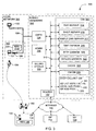
- Figure 1 depicts a system 100 configured in accordance with the invention to facilitate communication between each of a pair of clients 102 and 103 on a cable subnet 105 and information resources available on the Internet 106.
- Figure 2 is a flowchart 200 depicting a process of initiating a service agreement between a prospective Internet user and an Internet service provider.
- Figure 3 depicts another system 300 configured in accordance with the invention to facilitate bi-directional communication between clients 102 and 103 and information resources available on the Internet 106.
- Figure 4 is a flowchart 400 depicting a process of initiating a service agreement between a prospective Internet user and an Internet service provider.
- Figure 5 is a flowchart 500 depicting the process of Figure 4 from the perspective of a client controlled by the prospective user.
- Figure 1 depicts a system 100 configured in accordance with the invention to facilitate bi-directional communication between each of a pair of clients 102 and 103 on a cable subnet 105 and resources available on the Internet 106 (or some other network or collection of networks).
- Cable subnet 105 connects to the Internet 106 via subnet hardware 108.
- subnet hardware 108 enables clients 102 and 103 to register for Internet service with one of a number of Internet service providers (ISPs) 116, 118, and 120.
- ISPs 116, 118, and 120 connect to the Internet 106 via respective connections 122, 124, and 126.
- Cable subnet 105 and subnet hardware 108 collectively form a local network 109 through which clients 102 and 103 can access the Internet 106.
- Client 102 is a set-top box equipped with an internal cable modem; client 103 includes a personal computer 127 connected to cable subnet 105 using an external cable modem 128. Each of clients 102 and 103 conventionally contains a unique media-access control (MAC) address, though only MAC address 129 for client 103 is shown. A computer user 130 is responsible for contracting with an ISP to receive Internet access via client 103.
- MAC media-access control
- Subnet hardware 108 includes a conventional router 132 connected to a conventional Cable Modem Termination System (CMTS) 134 via a TCP/IP subnet 135.
- CMTS Cable Modem Termination System
- CMTS 134 facilitates bi-directional information transfer between cable 105 and a TCP/IP network, such as the Internet 106.
- TCP/IP network such as the Internet 106.
- subnet hardware 108 additionally includes cable-modem infrastructure (CMI) 136 connected to both CMTS 134 and router 132 via subnet 135.
- CMI 136 includes a MAC database 140, listing which clients on local network 102 are registered with an ISP, and a CMI callout 138 that bars unregistered devices from accessing the Internet and that allows unregistered devices to register for Internet service with authorized ISPs.
- Authorized ISPs are listed in CMI callout 138 as ISP list 142.
- ISP list 142 lists only ISP 116 and 118. The remaining ISP 120 is not authorized to provide service to clients on cable subnet 105, perhaps because the administrator of ISP 120 has not contracted with the administrator of local network 109 to provide service to clients on local network 109.
- the dashed line delineating the boundary of local network 109 includes clients 102 and 103 and subnet hardware 108. Strictly speaking, however, local network 109 only includes cable subnet 105, CMTS 134, and TCP/IP subnet 135. Router 132 defines the boundary between local network 109 and the Internet 106.
- ISP 116 includes an administrator 146 and an ISP registry 148.
- Administrator 146 can be either human or an automated user interface with which user 130 can establish an Internet-service agreement 150, illustrated as a "handshake" between administrator 146 and user 130.
- ISPs 118 and 120 may have administrators and registration databases similar to those of ISP 116.
- Figure 2 is a flowchart 200 depicting a process of initiating service agreement 150 of Figure 1 between user 130 and administrator 146 of ISP 116, also of Figure 1. Such an agreement typically affords user 130 access to Internet resources via client 103.
- the first digit of each reference number in this document corresponds to the number of the figure in which the identified element was first introduced.
- modem 128 and CMTS 134 employ conventional protocols to communicate over cable subnet 105.
- CMTS 134 converts between RF signals on cable subnet 105 and digital signals that can be understood by devices on subnet 135.
- modem 128 transmits a message that includes MAC address 129.
- CMI callout 138 intercepts this message and determines whether modem 128 is registered with an ISP, and therefore has access to the Internet 106.
- CMI callout 138 makes this determination by looking to MAC database 140 for an entry identifying MAC address 129 (decision 204). If the answer is yes, then CMI 136 provides modem 128 with an IP address selected from a pool of ISP addresses stored within CMI callout 138.
- CMI callout 138 provides modem 128 with a non-routable IP address (step 208).
- the non-routable IP address allows modem 128 to communicate with resources on subnet 135; however, router 132 blocks modem 128 from communicating over the Internet 106.
- CMI callout 138 then stores MAC address 129 and the corresponding non-routable IP address in database 140 (step 210).
- CMI server will receive one of two requests from client 103, depending upon whether additional devices within client 103 require an IP address.
- Computer 127 is a network device, and therefore requires its own IP address. Computer 127 typically transmits an address request a number of times before CMI 136 provides modem 128 with an IP address, thereby enabling modem 128 to communicate requests from computer 127.
- the process Upon receiving an address request from computer 127 (step 211), the process returns to decision 204. Computer 127 will then go through steps 208 and 210 as described above for modem 128.
- modem 128 and 127 have been through steps 208 and 210, both devices have non-routable IP addresses that can be used to communicate with entities on local network 109.
- User 130 then begins the registration process by starting the browser on computer 127 and directing the browser to connect to a login page stored in CMI 136. This connection initiates a registration request to CMI 136 (step 211).
- the address of the login page might be provided to user 130 in the installation instructions for modem 128 or by the company that controls local network 109.
- the browser of computer 127 is factory configured to automatically connect to the appropriate login page when started.
- CMI 136 responds to the registration request of step 211 by sending ISP list 142 to client 103 (step 212) and facilitating communication between client 103 and a selected ISP (step 214).
- CMI 136 thus enables user 130 to register client 103 with an ISP on the Internet 106 without requiring client 103 have a routable IP address.
- next two steps 216 and 218 are set out with dashed lines to emphasize that they are not separate steps performed by CMI 136, but are instead accomplished between user 130 and administrator 146 of ISP 116 during step 214.
- User 130 selects an ISP from ISP list 142 (step 216) and completes an Internet-service agreement with the administrator of the selected ISP (step 218).
- user 130 is assumed to have selected ISP 116 and entered into agreement 150 with administrator 146.
- CMI callout 138 modifies the entry in database 140 corresponding to the MAC address of computer 127 (step 222) to indicate that computer 127 is registered with the selected ISP.
- CMI 136 also requests that computer 127 release its non-routable IP address and request a new one (step 224). Computer 127 complies with these requests, returning the process to step 203. With computer 127 registered, subsequent requests from computer 127 for IP addresses pass through decision 204 to step 226, in which computer 127 receives a routable IP address.
- modem 128 does not communicate with devices outside of local network 109, and consequently need not register with an ISP to receive a routable IP address.
- modem 128 registers to receive a routable IP address and then uses that address to provide Internet access to any number of devices, such as collection of computers like computer 127.
- modem 128 acts as a DHCP server that provides local IP addresses for each of the computers.
- Modem 128 then translates these local IP addresses to the routable IP address assigned to modem 128 during the registration process.
- modem 128 and the associated collection of computers appear as a single device with a single MAC address and a single IP address.
- CMI callout 138 communicates with CMTS 134 to receive a service-flow identifier (SFID) associated with modem 128. All devices behind modem 128 (e.g., computer 127) then automatically use the same SFID as modem 128.
- SFID service-flow identifier
- CMI callout 138 requests the SFID associated with the requesting device from CMTS 134; if that SFID matches one for a registered modem, then CMI callout 138 provides a routable IP address. Otherwise, the requesting device is directed through the registration process discussed above. Thereafter, modem 128 will be marked in database 140 as registered, which will allow all devices behind the modem to receive routable IP addresses.
- Figure 3 depicts a system 300 configured in accordance with the invention.
- Various elements of Figure 3 were described above in connection with Figure 1, like-numbered elements being similar.
- cable subnet 105, the Internet 106, and each component connected directly to cable subnet 105 and the Internet 106 are identical to the like-numbered elements of Figure 1.
- subnet hardware 302 facilitates communication between devices on cable subnet 105 and devices on the Internet 106.
- Subnet hardware 302 includes the same conventional router 132 and CMTS 134 described in connection with Figure 1.
- Subnet hardware 302 and cable subnet 105 are parts of a local network 303 controlled by e.g. a local cable company.
- Router 132 defines the boundary between local network 303 and the Internet 106.
- Subnet hardware 302 includes cable-modem infrastructure (CMI) 304, a network administration interface 306, and a billing system 308, all interconnected by a TCP/IP subnet 312.
- CMI 304 includes a registration server 314, a DHCP server 316, a simple DNS server 317, a TIME daemon 318, a TFTP daemon 320, a SYSLOG daemon 322, a cache 326, a CMI database 328, and a DHCP callout 330.
- DHCP stands for "Dynamic Host Configuration Protocol.”
- DHCP server 316 passes configuration data and reusable network addresses to clients 102 and 103.
- DHCP server 316 uses a standard protocol specified in Request for Comment (RFC) 2131, entitled “Dynamic Host Configuration Protocol,” by R. Droms (March 1997), which is incorporated herein by reference.
- RRC Request for Comment
- DCHP callout 330 is an Application Program Interface (API) that intercepts address requests from clients 102 and 103 directed to DHCP server 316, and intercepts responses from DHCP server 316 directed to clients 102 and 103.
- DHCP callout 330 caches messages from clients 102 and 103 in cache 326 to avoid unnecessary database lookups in response to redundant client requests.
- DHCP callout 330 includes a list 331 of ISPs with which clients on local network 303 may enter into a service agreement. Callout 330 bars unregistered devices from accessing the Internet and allow unregistered devices to register for Internet service. In the present example, DHCP callout 330 lists only ISPs 116 and 118.
- DHCP callout 330 additionally includes a local address pool 332 of non-routable IP addresses and an IP address pool 333 with IP addresses for use with each listed ISP.
- DCHP callout 330 is described below in more detail in connection with Figure 4.
- TIME daemon 318 provides the time and date to network clients so that cable modems do not require battery operated clocks.
- "Daemon” is a conventional term used to describe a program that is activated, when needed, without user intervention.
- TIME daemon 318 uses a standard protocol specified in RFC 868, entitled “Time Protocol,” by J. Postel and K. Harrenstien (May 1983), which is incorporated herein by reference.
- TFTP stands for “Trivial File Transfer Protocol.”
- TFTP daemon 320 implements a simple file-transfer service that CMI 304 uses to provide configuration files to clients 102 and 103.
- TFTP daemon 320 uses a standard protocol specified in RFC 1350, entitled “The TFTP Protocol (Revision 2)” by K. Sollins (July 1992), which is incorporated herein by reference.
- SYSLOG daemon 322 provides a standard Application Program Interface (API) that allows clients 102 and 103 to log errors in a single location. For example, once modem 128 receives an IP address, modem 128 will send error messages over local network 303 to SYSLOG daemon 322 for logging. This allows administrator 306 to check for error messages in a single location.
- API Application Program Interface
- CMI database 328 defines a number of fields that correlate MAC addresses from network clients with information specific to each client. For example, CMI database 328 lists, for each registered client, the type of modem, the ISP with which the client is registered, and the client's billing status. A specific embodiment of database 328 is detailed in "Cable Modem Infrastructure Guide, Microsoft® TV Server 1.0 Deployment Pre-Release,” from WebTV Networks, Inc. (September 29, 1999 - 3pm), which is incorporated herein by reference.
- Figure 4 is a flowchart 400 depicting a process of initiating service agreement 150 ( Figures 1 and 3) between user 130 and administrator 146 of ISP 116.
- modem 128 and CMTS 134 establish communication between subnet 105 and TCP/IP subnet 312.
- Modem 128 then transmits a DHCP discover message asking for DHCP servers on local network 303.
- DHCP callout 330 receives and intercepts the discover message (step 402), which includes MAC address 129, and checks to see whether MAC address 129 is listed in database 328 (decision 404).
- DHCP callout 330 adds MAC address 129 and some default modem settings to both database 328 and cache 326 (step 408).
- Caching MAC 129 and the default settings speeds step 404 in the event that CMI 304 receives more than one discover message from modem 128. Such a repeat message might occur during high load situations or when a malicious user attempts to disrupt local network 303 by sending a stream of repeat messages.
- DHCP server 316 responds to the DHCP discover message with a DHCP offer message (step 410) that includes an available non-routable IP address from local address pool 332 and conventional configuration parameters for use by modem 128.
- Modem 128 responds to the DHCP offer message by broadcasting a DHCP request message addressed to DHCP server 316.
- DHCP server 316 then receives the request message (step 414) and returns a DCHP response message to modem 128 (step 416).
- the DCHP response message provides modem 128 with configuration parameters, including a committed non-routable IP address from local address pool 332 and the IP addresses of devices on local network 303 with which modem 128 may have to communicate.
- Such devices include simple DNS server 317, time daemon 318, tftp daemon 320, and syslog daemon 322.
- modem 128 accesses the addressed devices to obtain configuration information and, in the case of syslog daemon 322, to report any errors. This completes the boot process of modem 128, leaving modem 128 able to communicate information to and from computer 127.
- CMI callout 138 then flushes cache 326 (step 417) and stores the assigned IP address and default configuration data in database 328 (step 418) with MAC address 129.
- a device behind cable modem 128 may require an additional IP address.
- computer 127 needs an IP address and will therefore issue a DHCP discover request.
- Computer 127 may issue this request a number of times before modem 128 receives an IP address enabling modem 128 to convey the request from computer 127.
- DHCP discover message from computer 127 (step 419)
- the process returns to decision 404.
- computer 127 is not registered. Thus, the MAC address of computer 127 is not listed in cache 326 or database 328. Consequently, computer 127 proceeds from step 408 through step 418 in the same manner that modem 128 traversed those steps. Thus, the second time the process arrives at step 419, both modem 128 and computer 127 are listed in database 328.
- both modem 128 and computer 127 have non-routable IP addresses that can be used to communicate with entities on local network 303. Further, computer 127 has been provided with the addressing information required for computer 127 to communicate with various elements of CMI 304, including registration server 314.
- User 130 begins the registration process by starting the browser on computer 127 and, if the browser is not configured to do so automatically, directing the browser to connect to a login page, http://login , in one embodiment.
- the DHCP response message set the DNS server entry in computer 127 to simple DNS 317.
- the hostname "login" on simple DNS server 317 points to the self-registration page on registration server 314.
- registration server 314 requests a token and ISP list 331 from DHCP callout 330.
- the token is a key given to client 103 to present to an ISP when registering with the ISP.
- the ISP will have to present the token back to CMI 304 to authenticate that client 103 registered with the ISP.
- the use of a token thus ensures that user 130 entered into a service agreement with the ISP.
- the token is a 64-bit random number.
- callout 330 presents the requested token and ISP list 331 to registration server 314 and stores the token in database 328 with the MAC address of computer 127 (step 422).
- Registration server 314 then forwards the token and ISP list 131 to computer 127 and prompts user 130 to select from among the listed ISPs.
- user 130 is presented with the registration page of the selected ISP (e.g., a page in registry 148 of- ISP 116) by way of registration server 314.
- registration server 314 acts as a TCP/IP proxy and routes data between client 103 and ISP 116.
- Registry 148 prompts user 130 for registration data and requests a list of available IP and service classes from CMI 304. Registry 148 then presents the available IP and service classes to user 130, who then selects a service class from the list.
- IP classes are used when a single ISP has multiple pools of IP addresses. Addresses from different pools may be routed differently, through better network connections, for example. Service classes specify what level of service a user receives within a given pool of IP addresses. For example, a particular user may receive higher priority than others in the same IP class.
- ISP registry 148 receives this message and, if the token is the same one originally supplied to computer 127, modifies the entry in database 328 corresponding to computer 127 (step 426) to include the ISP settings and to indicate that computer 127 is registered with the selected ISP.
- callout 330 Upon completion of the registration process, callout 330 requests that computer 127 release and re-request its IP address (step 428). Computer 127 thus releases its non-routable IP address and transmits a new DHCP discover message. Callout 330 receives the DHCP request (step 203) and again examines the MAC entry of computer 127 to determine whether computer 127 is listed in database 328. Because computer 127 was so listed in step 408, the process moves to step 430 in which callout 330 determines whether computer 127 is listed in database 328 as "blocked.”
- a particular client or device may be listed as "blocked" for many reasons.
- an administrator in the local cable company controlling local network 303 might block access from a device found to be distributing illegal or offensive content, or a member of the cable company's billing department might block access to cable subscribers who are unwilling to pay for the service.
- Administration interface 306 and billing-system interface 308 are Component Object Model (COM) interfaces that afford cable-company employees access to database 328 for these and other purposes.
- COM Component Object Model
- CMI callout 330 examines a second field in database 328 corresponding to the respective MAC address, this time to determine whether computer 127 is registered with an ISP (decision 432). In the example, computer 127 is registered with ISP 116, so callout 330 issues computer 127 a routable IP address from address pool 333. Had computer 127 not been registered, then the process flow would move to step 410 and would continue as described above.
- a client might be listed in database 328 but not registered if, for example, the user did not complete a registration process.
- a user or an ISP might send a message to registration server 314 indicating the cessation of a registration agreement between the user and the ISP. Registration server 314 could then mark the user's client as unregistered without removing the associated MAC address from database 328.
- FIG. 5 is a flowchart 500 depicting the process of initiating service agreement 150 between user 130 and administrator 146 of ISP 116 from the perspective of client 103.
- modem 128 and CMTS 134 communicate over cable subnet 105 to establish a connection between cable subnet 105 and TCP/IP subnet 312.
- Modem 128 then transmits a DHCP discover message (step 502) asking for DHCP servers on local network 303.
- Modem 128 can expect one of three responses:
- the browser connects to its login page, http://login , either automatically or as directed by user 130 (step 522).
- Registration server 314 requests and receives a token and ISP list 331 from DHCP callout 330.
- Registration server 314 then sends the token and list to computer 127. Having received the token and ISP list 331 (step 523), user 130 selects from among the listed ISPs (step 524).
- Registration server 314 facilitates communication between client 103 and the selected ISP so that user 130 can register computer 127 with the selected ISP.
- computer 127 receives a request from CMI 304 instructing computer 127 to release the assigned IP address and request another (step 526).
- Computer 127 then releases its non-routable IP address (step 528) and acquires a new IP address by issuing a new DHCP discover message (returning to step 502).
- CMI 304 responds to the DHCP discover message with a routable IP address (step 504) that allows computer 127 to access the Internet 106.
Abstract
Description
- The invention relates to network-device registration systems that allow devices on a local network, such as a cable network, to register with Internet service providers to obtain access to the Internet.
- Cable modems handle incoming and outgoing data signals between a cable provider and a personal or business computer or television set. Cable modems are quickly replacing telephone modems in many areas because of the cable modem's superior bandwidth.
- DOCSIS (Data Over Cable Systems Interface Specifications) is an industry standard that specifies an interface for cable modems. More specifically, DOCSIS specifies modulation schemes and protocols for exchanging bi-directional signals between devices on a cable network and devices on a TCP/IP network, typically the Internet.
- DOCSIS describes a method by which a cable modem can receive an IP address to gain connectivity to the Internet. This method is sufficient for the simple case where the cable provider supplies cable modems to cable customers, who then access the Internet through an Internet Service Provider (ISP) specified by the cable provider. However, there is no provision for cable customers to receive IP addresses for cable modems that are not supplied by their cable provider. Moreover, there is no provision for allowing cable customers to select from among several ISPs on a single cable network. There is therefore a need for a system that allows cable customers to choose both the cable modem through which they access the Internet and the ISP that will provide them that access.
- The present invention is directed to methods and apparatus that let cable customers who wish to add a cable modem (or other device) to a local cable network choose both the cable modem through which they access the Internet and the ISP that will provide them that access.
- A system of hardware configured in accordance with one embodiment of the invention connects the local network to the Internet. This hardware includes cable-modem infrastructure (CMI) that denies Internet access to devices on the local network that are not registered with an ISP authorized by the cable company. The hardware also facilitates the registration process, allowing devices new to the local network to establish Internet-access agreements with ISPs, and thereby gain access to the Internet.
- Every network device, including cable modems, has a unique identification code called a media-access control (MAC) address. New devices connected to the local network send their MAC address out onto the local network in an effort to obtain a routable IP address (i.e., an IP address that can be used to gain access to the Internet). The CMI intercepts such requests and looks in a MAC database to determine whether the device associated with the MAC address is registered with an ISP, and is therefore entitled to a routable IP address. If the MAC address is not listed, the CMI assigns the modem a non-routable address that can be used on the local network, but cannot be used to gain access to the Internet. The unregistered device can then use the non-routable address to communicate with a registration server in the CMI. The registration server is adapted to facilitate communication between the device and a selected ISP.
- Using the non-routable IP address and the registration server, a user of the network device enters into an agreement with a selected ISP. The selected ISP sends a message to the CMI identifying the device, the ISP, and the existence of the service agreement. The CMI then modifies the MAC database to indicate that the device is now registered. The CMI responds to subsequent address requests from the now-registered device with a routable IP address.
- Other features of the present invention will be apparent from the accompanying drawings and from the detailed description that follows.
- Figure 1 depicts a
system 100 configured in accordance with the invention to facilitate communication between each of a pair ofclients cable subnet 105 and information resources available on the Internet 106. - Figure 2 is a
flowchart 200 depicting a process of initiating a service agreement between a prospective Internet user and an Internet service provider. - Figure 3 depicts another
system 300 configured in accordance with the invention to facilitate bi-directional communication betweenclients - Figure 4 is a
flowchart 400 depicting a process of initiating a service agreement between a prospective Internet user and an Internet service provider. - Figure 5 is a
flowchart 500 depicting the process of Figure 4 from the perspective of a client controlled by the prospective user. - Figure 1 depicts a
system 100 configured in accordance with the invention to facilitate bi-directional communication between each of a pair ofclients cable subnet 105 and resources available on the Internet 106 (or some other network or collection of networks). -
Cable subnet 105 connects to the Internet 106 viasubnet hardware 108. In accordance with the invention,subnet hardware 108 enablesclients ISPs respective connections Cable subnet 105 andsubnet hardware 108 collectively form alocal network 109 through whichclients -
Client 102 is a set-top box equipped with an internal cable modem;client 103 includes apersonal computer 127 connected tocable subnet 105 using anexternal cable modem 128. Each ofclients MAC address 129 forclient 103 is shown. Acomputer user 130 is responsible for contracting with an ISP to receive Internet access viaclient 103. - Subnet
hardware 108 includes aconventional router 132 connected to a conventional Cable Modem Termination System (CMTS) 134 via a TCP/IP subnet 135. A detailed discussion ofCMTS 134, sometime referred to as a cable network "headend," is beyond the scope of the present disclosure. It is enough to note that CMTS 134 facilitates bi-directional information transfer betweencable 105 and a TCP/IP network, such as the Internet 106. For a detailed discussion of CMTS 134, see the document entitled "Cable Modem Termination System-Network Side Interface Specification," SP-CMTS-NSII01-960702 (1996), which is incorporated herein by reference. - In accordance with the invention,
subnet hardware 108 additionally includes cable-modem infrastructure (CMI) 136 connected to both CMTS 134 androuter 132 viasubnet 135. CMI 136, in turn, includes aMAC database 140, listing which clients onlocal network 102 are registered with an ISP, and aCMI callout 138 that bars unregistered devices from accessing the Internet and that allows unregistered devices to register for Internet service with authorized ISPs. Authorized ISPs are listed inCMI callout 138 asISP list 142. - In the present example,
ISP list 142 lists onlyISP remaining ISP 120 is not authorized to provide service to clients oncable subnet 105, perhaps because the administrator ofISP 120 has not contracted with the administrator oflocal network 109 to provide service to clients onlocal network 109. - The dashed line delineating the boundary of
local network 109 includesclients subnet hardware 108. Strictly speaking, however,local network 109 only includescable subnet 105, CMTS 134, and TCP/IP subnet 135.Router 132 defines the boundary betweenlocal network 109 and the Internet 106. -
ISP 116 includes anadministrator 146 and anISP registry 148.Administrator 146 can be either human or an automated user interface with whichuser 130 can establish an Internet-service agreement 150, illustrated as a "handshake" betweenadministrator 146 anduser 130.ISPs ISP 116. - Figure 2 is a
flowchart 200 depicting a process of initiatingservice agreement 150 of Figure 1 betweenuser 130 andadministrator 146 ofISP 116, also of Figure 1. Such an agreement typically affordsuser 130 access to Internet resources viaclient 103. (Incidentally, the first digit of each reference number in this document corresponds to the number of the figure in which the identified element was first introduced.) - Beginning at step 202,
modem 128 and CMTS 134 employ conventional protocols to communicate overcable subnet 105.CMTS 134 converts between RF signals oncable subnet 105 and digital signals that can be understood by devices onsubnet 135. Having established communication withsubnet 135,modem 128 transmits a message that includesMAC address 129. CMIcallout 138 intercepts this message and determines whethermodem 128 is registered with an ISP, and therefore has access to the Internet 106.CMI callout 138 makes this determination by looking toMAC database 140 for an entry identifying MAC address 129 (decision 204). If the answer is yes, thenCMI 136 providesmodem 128 with an IP address selected from a pool of ISP addresses stored withinCMI callout 138. - If
MAC 129 is not registered, thenCMI callout 138 providesmodem 128 with a non-routable IP address (step 208). The non-routable IP address allowsmodem 128 to communicate with resources onsubnet 135; however,router 132blocks modem 128 from communicating over theInternet 106.CMI callout 138 then storesMAC address 129 and the corresponding non-routable IP address in database 140 (step 210). - CMI server will receive one of two requests from
client 103, depending upon whether additional devices withinclient 103 require an IP address.Computer 127 is a network device, and therefore requires its own IP address.Computer 127 typically transmits an address request a number of times beforeCMI 136 providesmodem 128 with an IP address, thereby enablingmodem 128 to communicate requests fromcomputer 127. Upon receiving an address request from computer 127 (step 211), the process returns todecision 204.Computer 127 will then go throughsteps modem 128. - Once
modem steps local network 109.User 130 then begins the registration process by starting the browser oncomputer 127 and directing the browser to connect to a login page stored inCMI 136. This connection initiates a registration request to CMI 136 (step 211). The address of the login page might be provided touser 130 in the installation instructions formodem 128 or by the company that controlslocal network 109. In another embodiment, the browser ofcomputer 127 is factory configured to automatically connect to the appropriate login page when started. -
CMI 136 responds to the registration request ofstep 211 by sendingISP list 142 to client 103 (step 212) and facilitating communication betweenclient 103 and a selected ISP (step 214).CMI 136 thus enablesuser 130 to registerclient 103 with an ISP on theInternet 106 without requiringclient 103 have a routable IP address. - The next two steps 216 and 218 are set out with dashed lines to emphasize that they are not separate steps performed by
CMI 136, but are instead accomplished betweenuser 130 andadministrator 146 ofISP 116 duringstep 214.User 130 selects an ISP from ISP list 142 (step 216) and completes an Internet-service agreement with the administrator of the selected ISP (step 218). For illustrative purposes,user 130 is assumed to have selectedISP 116 and entered intoagreement 150 withadministrator 146. - Once
user 130 andadministrator 146 finalizeagreement 150, thenadministrator 146 notes the agreement inregistry 148 and notifiesCMI 136 thatcomputer 127 is registered. Upon receipt of this notice (step 220),CMI callout 138 modifies the entry indatabase 140 corresponding to the MAC address of computer 127 (step 222) to indicate thatcomputer 127 is registered with the selected ISP.CMI 136 also requests thatcomputer 127 release its non-routable IP address and request a new one (step 224).Computer 127 complies with these requests, returning the process to step 203. Withcomputer 127 registered, subsequent requests fromcomputer 127 for IP addresses pass throughdecision 204 to step 226, in whichcomputer 127 receives a routable IP address. - In the embodiment of Figure 2,
modem 128 does not communicate with devices outside oflocal network 109, and consequently need not register with an ISP to receive a routable IP address. In other embodiments,modem 128 registers to receive a routable IP address and then uses that address to provide Internet access to any number of devices, such as collection of computers likecomputer 127. In that embodiment,modem 128 acts as a DHCP server that provides local IP addresses for each of the computers.Modem 128 then translates these local IP addresses to the routable IP address assigned tomodem 128 during the registration process. Thus, from the perspective of devices outside ofclient 103,modem 128 and the associated collection of computers appear as a single device with a single MAC address and a single IP address. - In another embodiment,
CMI callout 138 communicates withCMTS 134 to receive a service-flow identifier (SFID) associated withmodem 128. All devices behind modem 128 (e.g., computer 127) then automatically use the same SFID asmodem 128. WhenCMI callout 138 receives a new DHCP request,callout 138 requests the SFID associated with the requesting device fromCMTS 134; if that SFID matches one for a registered modem, thenCMI callout 138 provides a routable IP address. Otherwise, the requesting device is directed through the registration process discussed above. Thereafter,modem 128 will be marked indatabase 140 as registered, which will allow all devices behind the modem to receive routable IP addresses. - Figure 3 depicts a
system 300 configured in accordance with the invention. Various elements of Figure 3 were described above in connection with Figure 1, like-numbered elements being similar. For example,cable subnet 105, theInternet 106, and each component connected directly tocable subnet 105 and theInternet 106, are identical to the like-numbered elements of Figure 1. - In
system 300,subnet hardware 302 facilitates communication between devices oncable subnet 105 and devices on theInternet 106.Subnet hardware 302 includes the sameconventional router 132 andCMTS 134 described in connection with Figure 1.Subnet hardware 302 andcable subnet 105 are parts of alocal network 303 controlled by e.g. a local cable company.Router 132 defines the boundary betweenlocal network 303 and theInternet 106. -
Subnet hardware 302 includes cable-modem infrastructure (CMI) 304, anetwork administration interface 306, and abilling system 308, all interconnected by a TCP/IP subnet 312.CMI 304 includes aregistration server 314, aDHCP server 316, asimple DNS server 317, aTIME daemon 318, aTFTP daemon 320, aSYSLOG daemon 322, acache 326, aCMI database 328, and aDHCP callout 330. - DHCP stands for "Dynamic Host Configuration Protocol."
DHCP server 316 passes configuration data and reusable network addresses toclients DHCP server 316 uses a standard protocol specified in Request for Comment (RFC) 2131, entitled "Dynamic Host Configuration Protocol," by R. Droms (March 1997), which is incorporated herein by reference. -
DCHP callout 330 is an Application Program Interface (API) that intercepts address requests fromclients DHCP server 316, and intercepts responses fromDHCP server 316 directed toclients DHCP callout 330 caches messages fromclients cache 326 to avoid unnecessary database lookups in response to redundant client requests.DHCP callout 330 includes alist 331 of ISPs with which clients onlocal network 303 may enter into a service agreement.Callout 330 bars unregistered devices from accessing the Internet and allow unregistered devices to register for Internet service. In the present example,DHCP callout 330 lists onlyISPs DHCP callout 330 additionally includes alocal address pool 332 of non-routable IP addresses and anIP address pool 333 with IP addresses for use with each listed ISP.DCHP callout 330 is described below in more detail in connection with Figure 4. - "TIME"
daemon 318 provides the time and date to network clients so that cable modems do not require battery operated clocks. "Daemon" is a conventional term used to describe a program that is activated, when needed, without user intervention.TIME daemon 318 uses a standard protocol specified in RFC 868, entitled "Time Protocol," by J. Postel and K. Harrenstien (May 1983), which is incorporated herein by reference. - "TFTP" stands for "Trivial File Transfer Protocol."
TFTP daemon 320 implements a simple file-transfer service that CMI 304 uses to provide configuration files toclients TFTP daemon 320 uses a standard protocol specified in RFC 1350, entitled "The TFTP Protocol (Revision 2)" by K. Sollins (July 1992), which is incorporated herein by reference. -
SYSLOG daemon 322 provides a standard Application Program Interface (API) that allowsclients modem 128 receives an IP address,modem 128 will send error messages overlocal network 303 toSYSLOG daemon 322 for logging. This allowsadministrator 306 to check for error messages in a single location. -
CMI database 328 defines a number of fields that correlate MAC addresses from network clients with information specific to each client. For example,CMI database 328 lists, for each registered client, the type of modem, the ISP with which the client is registered, and the client's billing status. A specific embodiment ofdatabase 328 is detailed in "Cable Modem Infrastructure Guide, Microsoft® TV Server 1.0 Deployment Pre-Release," from WebTV Networks, Inc. (September 29, 1999 - 3pm), which is incorporated herein by reference. - Figure 4 is a
flowchart 400 depicting a process of initiating service agreement 150 (Figures 1 and 3) betweenuser 130 andadministrator 146 ofISP 116. Beginning atstep 401,modem 128 andCMTS 134 establish communication betweensubnet 105 and TCP/IP subnet 312.Modem 128 then transmits a DHCP discover message asking for DHCP servers onlocal network 303.DHCP callout 330 receives and intercepts the discover message (step 402), which includesMAC address 129, and checks to see whetherMAC address 129 is listed in database 328 (decision 404). - Assuming that
modem 128 is new tolocal network 303 -- and therefore thatMAC address 129 is not listed indatabase 328 --DHCP callout 330 addsMAC address 129 and some default modem settings to bothdatabase 328 and cache 326 (step 408). CachingMAC 129 and the default settings speeds step 404 in the event thatCMI 304 receives more than one discover message frommodem 128. Such a repeat message might occur during high load situations or when a malicious user attempts to disruptlocal network 303 by sending a stream of repeat messages. -
DHCP server 316 responds to the DHCP discover message with a DHCP offer message (step 410) that includes an available non-routable IP address fromlocal address pool 332 and conventional configuration parameters for use bymodem 128.Modem 128 responds to the DHCP offer message by broadcasting a DHCP request message addressed toDHCP server 316.DHCP server 316 then receives the request message (step 414) and returns a DCHP response message to modem 128 (step 416). The DCHP response message providesmodem 128 with configuration parameters, including a committed non-routable IP address fromlocal address pool 332 and the IP addresses of devices onlocal network 303 with whichmodem 128 may have to communicate. Such devices includesimple DNS server 317,time daemon 318,tftp daemon 320, andsyslog daemon 322. Oncemodem 128 receives these parameters,modem 128 accesses the addressed devices to obtain configuration information and, in the case ofsyslog daemon 322, to report any errors. This completes the boot process ofmodem 128, leavingmodem 128 able to communicate information to and fromcomputer 127.CMI callout 138 then flushes cache 326 (step 417) and stores the assigned IP address and default configuration data in database 328 (step 418) withMAC address 129. - A device behind
cable modem 128 may require an additional IP address. In the present example,computer 127 needs an IP address and will therefore issue a DHCP discover request.Computer 127 may issue this request a number of times beforemodem 128 receives an IPaddress enabling modem 128 to convey the request fromcomputer 127. Upon receiving DHCP discover message from computer 127 (step 419), the process returns todecision 404. - In the example,
computer 127 is not registered. Thus, the MAC address ofcomputer 127 is not listed incache 326 ordatabase 328. Consequently,computer 127 proceeds fromstep 408 through step 418 in the same manner thatmodem 128 traversed those steps. Thus, the second time the process arrives atstep 419, bothmodem 128 andcomputer 127 are listed indatabase 328. - At this point, both
modem 128 andcomputer 127 have non-routable IP addresses that can be used to communicate with entities onlocal network 303. Further,computer 127 has been provided with the addressing information required forcomputer 127 to communicate with various elements ofCMI 304, includingregistration server 314. -
User 130 begins the registration process by starting the browser oncomputer 127 and, if the browser is not configured to do so automatically, directing the browser to connect to a login page, http://login, in one embodiment. Earlier (step 416), the DHCP response message set the DNS server entry incomputer 127 tosimple DNS 317. The hostname "login" onsimple DNS server 317 points to the self-registration page onregistration server 314. Thus, whenuser 130 starts the browser on theunregistered client 103, the browser automatically connects to the self-registration page. When the browser connects,registration server 314 requests a token andISP list 331 fromDHCP callout 330. The token is a key given toclient 103 to present to an ISP when registering with the ISP. The ISP will have to present the token back toCMI 304 to authenticate thatclient 103 registered with the ISP. The use of a token thus ensures thatuser 130 entered into a service agreement with the ISP. In one embodiment, the token is a 64-bit random number. - From
step 419,callout 330 presents the requested token andISP list 331 toregistration server 314 and stores the token indatabase 328 with the MAC address of computer 127 (step 422).Registration server 314 then forwards the token and ISP list 131 tocomputer 127 and promptsuser 130 to select from among the listed ISPs. Upon selecting an ISP,user 130 is presented with the registration page of the selected ISP (e.g., a page inregistry 148 of- ISP 116) by way ofregistration server 314. In effect,registration server 314 acts as a TCP/IP proxy and routes data betweenclient 103 andISP 116. -
Registry 148 promptsuser 130 for registration data and requests a list of available IP and service classes fromCMI 304.Registry 148 then presents the available IP and service classes touser 130, who then selects a service class from the list. IP classes are used when a single ISP has multiple pools of IP addresses. Addresses from different pools may be routed differently, through better network connections, for example. Service classes specify what level of service a user receives within a given pool of IP addresses. For example, a particular user may receive higher priority than others in the same IP class. - Once
user 130 andadministrator 146 finalizeagreement 150,administrator 146 adds the MAC address forcomputer 127 toISP registry 148 and notifiesCMI 136 thatcomputer 127 is registered. The notice fromISP registry 148 includes the token and various required ISP settings.Callout 138 receives this message and, if the token is the same one originally supplied tocomputer 127, modifies the entry indatabase 328 corresponding to computer 127 (step 426) to include the ISP settings and to indicate thatcomputer 127 is registered with the selected ISP. - Upon completion of the registration process,
callout 330 requests thatcomputer 127 release and re-request its IP address (step 428).Computer 127 thus releases its non-routable IP address and transmits a new DHCP discover message.Callout 330 receives the DHCP request (step 203) and again examines the MAC entry ofcomputer 127 to determine whethercomputer 127 is listed indatabase 328. Becausecomputer 127 was so listed instep 408, the process moves to step 430 in which callout 330 determines whethercomputer 127 is listed indatabase 328 as "blocked." - A particular client or device may be listed as "blocked" for many reasons. For example, an administrator in the local cable company controlling
local network 303 might block access from a device found to be distributing illegal or offensive content, or a member of the cable company's billing department might block access to cable subscribers who are unwilling to pay for the service.Administration interface 306 and billing-system interface 308 are Component Object Model (COM) interfaces that afford cable-company employees access todatabase 328 for these and other purposes. - If
computer 127 is not blocked,CMI callout 330 examines a second field indatabase 328 corresponding to the respective MAC address, this time to determine whethercomputer 127 is registered with an ISP (decision 432). In the example,computer 127 is registered withISP 116, so callout 330 issues computer 127 a routable IP address fromaddress pool 333. Hadcomputer 127 not been registered, then the process flow would move to step 410 and would continue as described above. A client might be listed indatabase 328 but not registered if, for example, the user did not complete a registration process. Alternatively, a user or an ISP might send a message toregistration server 314 indicating the cessation of a registration agreement between the user and the ISP.Registration server 314 could then mark the user's client as unregistered without removing the associated MAC address fromdatabase 328. - Figure 5 is a
flowchart 500 depicting the process of initiatingservice agreement 150 betweenuser 130 andadministrator 146 ofISP 116 from the perspective ofclient 103. Beginning atstep 501,modem 128 andCMTS 134 communicate overcable subnet 105 to establish a connection betweencable subnet 105 and TCP/IP subnet 312.Modem 128 then transmits a DHCP discover message (step 502) asking for DHCP servers onlocal network 303.Modem 128 can expect one of three responses: - 1. if
modem 128 is registered with an ISP, thenmodem 128 will receive a DHCP offer message containing a fully routable IP address (step 504) fromaddress pool 333; - 2. if
CMI 304 listsmodem 128 as a blocked device, thenmodem 128 will receive anerror message 509 fromCMI 304; and - 3. if
modem 128 is not registered with an ISP, thenmodem 128 will receive a DHCP offer message (step 510) fromCMI 304 containing a non-routable IP address.
The offer message of - 1.
time daemon 318 to get the time; - 2.
tftp daemon 320 to get a modem configuration file; - 3.
syslog daemon 322, as necessary, to report any errors; and - 4.
simple DNS server 317 to get the address ofregistration server 314, which contains the self-registration page. -
- If another device, such as
computer 127, requires an IP address, then that other device will send its own DHCP discover message (decision 520) and traverseflowchart 500 in the manner described above formodem 128. Assuming thatcomputer 127 requires an IP address, the process proceeds once again through the steps on the left-hand side offlowchart 500 to step 518. Bothmodem 128 andcomputer 127 then have non-routable IP addresses that can be used to communicate with entities onlocal network 303. Once each device withinclient 103 has a non-routable IP address, the registration process begins whenuser 130 starts the browser on computer 127 (step 521). - The browser connects to its login page, http://login, either automatically or as directed by user 130 (step 522).
Registration server 314 then requests and receives a token andISP list 331 fromDHCP callout 330.Registration server 314 then sends the token and list tocomputer 127. Having received the token and ISP list 331 (step 523),user 130 selects from among the listed ISPs (step 524).Registration server 314 facilitates communication betweenclient 103 and the selected ISP so thatuser 130 can registercomputer 127 with the selected ISP. - Once registered,
computer 127 receives a request fromCMI 304 instructingcomputer 127 to release the assigned IP address and request another (step 526).Computer 127 then releases its non-routable IP address (step 528) and acquires a new IP address by issuing a new DHCP discover message (returning to step 502). Becausecomputer 127 is now registered,CMI 304 responds to the DHCP discover message with a routable IP address (step 504) that allowscomputer 127 to access theInternet 106. - While the present invention has been described in connection with specific embodiments, variations of these embodiments will be apparent. For example, while described in connection with cable-modem networks, the invention is equally applicable to other types of local networks. Therefore, the spirit and scope of the appended claims should not be limited to the foregoing description.
Claims (21)
- A method for initiating a service agreement between a user of a network device on a first network and one of a plurality of service providers having corresponding servers on a second network, wherein the network device includes an identification code unique to the first network, the method comprising:a. receiving the code from the network device;b. transmitting a message to the network device, the message including a list of the service providers;c. prompting the user to select one of the service providers and establish the service agreement with the selected one of the service providers; andd. receiving a notice from the selected one of the service providers, the notice identifying the network device and the selected one of the service providers.
- The method of claim 1, further comprising storing at least a portion of the notice.
- The method of claim 1, further comprising receiving a request for a second address unique on the first and second networks before (a), and refusing the request until after (d).
- The method of claim 1, wherein the notice includes the code.
- The method of claim 1, wherein the message to the network device includes a token, and wherein the notice from the selected one of the service providers also includes the token.
- A method for initiating a service agreement between a user of a network device on a first network and a service provider on a second network, wherein the network device includes at least one identification code unique to the first network, the method comprising:a. receiving the code from the network device;b. assigning a local IP address to the network device;c. transmitting the code and the local IP address to the network device, the local IP address allowing the network device to communicate with at least one of a first plurality of devices on the first network, but not allowing the network device to communicate with a second plurality of devices on the second network;d. prompting the user to establish the service agreement with the service provider;e. receiving a notice from the service provider, the notice identifying at least one of the network device and the user of the network device; andf. assigning a global IP address to the network device, the global IP address allowing the network device to communicate with the second plurality of devices on the second network.
- The method of claim 6, further comprising prompting the user to select the service provider from a plurality of service providers.
- The method of claim 6, further comprising storing the code and a second code identifying the service provider after (e).
- A local network system comprising:a. a plurality of cable modems connected to one another via a cable network, each of the modems including a corresponding unique identifier;b. a network headend having a first network node connected to the cable network and a second network node;c. an address server connected to the second network node of the headend, the address server including a modem database adapted to store the identifiers of the cable modems;d. a router connected between the local network and a second network;e. an ISP server connected to the router via the second network.
- The local network system of claim 9, wherein the headend is a CMTS headend.
- The local network system of claim 9, wherein the address server is a DHCP server.
- A system for establishing communication between a network computer connected to a local network and a remote information store connected to a second network, the system comprising:a. a server connected to the local network and adapted to:i. receive a unique identifier from the network computer and, in response, assign a non-routable address to the network computer, wherein the non-routable address is unique to the local network;ii. facilitate an agreement between a user of the network computer and an entity authorized to grant the network computer access to the second network; andiii. store the unique identifier in a database identifying the network computer as a registered network computer;b. an address server connected to the local network and adapted to assign a routable IP address to the registered network computer.
- The system of claim 12, wherein the local network comprises a cable network.
- The system of claim 12, wherein the second network comprises the Internet.
- The system of claim 14, wherein the entity authorized to grant the network computer access to the second network is an Internet Service Provider.
- The system of claim 14, wherein the remote information store is an Internet resource.
- A method of establishing communication between a network computer connected to a local network and a remote information store connected to a second network, the method comprising:a. receiving a unique identifier from the network computer;b. determining, based on the unique identifier from the network computer, whether the network computer has authority to access the second network; andc. if the network computer lacks authority to access the second network,i. providing a non-routable address to the network computer, wherein the non-routable address lacks authority to access the second network;ii. facilitating an agreement between a user of the network computer and an entity authorized to grant the network computer access to the second network; andiii. providing the network computer a routable address with authority to access the second network upon completion of the agreement.
- A method of establishing communication between a network computer connected to a local network and a remote information store connected to a second network, the method comprising:a. sending a unique identifier from the network computer;b. receiving a non-routable address, wherein the non-routable address lacks authority to access the second network;c. receiving, from a device on the local network, a list identifying a plurality of service providers on the second network; andd. selecting one of the plurality of service providers.
- The method of claim 18, further comprising receiving a token from the device on the local network and sending the token to the selected one of the plurality of service providers.
- The method of claim 18, further comprising receiving a token from the device on the local network and sending the token to the selected one of the plurality of service providers through the device on the local network.
- The method of claim 18, further comprising receiving a request to release the non-routable address after (d).
Applications Claiming Priority (2)
| Application Number | Priority Date | Filing Date | Title |
|---|---|---|---|
| US411012 | 1989-09-22 | ||
| US09/411,012 US6603758B1 (en) | 1999-10-01 | 1999-10-01 | System for supporting multiple internet service providers on a single network |
Publications (2)
| Publication Number | Publication Date |
|---|---|
| EP1089524A2 true EP1089524A2 (en) | 2001-04-04 |
| EP1089524A3 EP1089524A3 (en) | 2004-03-10 |
Family
ID=23627192
Family Applications (1)
| Application Number | Title | Priority Date | Filing Date |
|---|---|---|---|
| EP00308550A Withdrawn EP1089524A3 (en) | 1999-10-01 | 2000-09-28 | System for supporting multiple Internet service providers on a single network |
Country Status (2)
| Country | Link |
|---|---|
| US (1) | US6603758B1 (en) |
| EP (1) | EP1089524A3 (en) |
Cited By (4)
| Publication number | Priority date | Publication date | Assignee | Title |
|---|---|---|---|---|
| EP1349323A1 (en) * | 2002-03-29 | 2003-10-01 | Kabushiki Kaisha Toshiba | Source address selection system suitable for a multi-home environment |
| WO2003081875A1 (en) * | 2002-03-27 | 2003-10-02 | Siemens Aktiengesellschaft | Aaa server system for efficient access control and address assignment |
| WO2004062228A1 (en) * | 2002-12-19 | 2004-07-22 | Intel Corporation | Automatic wireless network login using embedded meta data |
| EP2566138A1 (en) | 2011-08-31 | 2013-03-06 | Liberty Global Europe Holding B.V. | Method and system for routing data traffic |
Families Citing this family (82)
| Publication number | Priority date | Publication date | Assignee | Title |
|---|---|---|---|---|
| US6370571B1 (en) | 1997-03-05 | 2002-04-09 | At Home Corporation | System and method for delivering high-performance online multimedia services |
| US7529856B2 (en) * | 1997-03-05 | 2009-05-05 | At Home Corporation | Delivering multimedia services |
| US8516055B2 (en) * | 1998-05-29 | 2013-08-20 | Research In Motion Limited | System and method for pushing information from a host system to a mobile data communication device in a wireless data network |
| US6996167B2 (en) * | 1999-09-14 | 2006-02-07 | Mindspeed Technologies, Inc. | Modem identification and diagnostics |
| US7092380B1 (en) * | 1999-10-22 | 2006-08-15 | Cisco Technology, Inc. | Method and system for providing voice communication over data networks |
| US7251820B1 (en) * | 1999-11-15 | 2007-07-31 | General Instruments Corporation | Method and system for automatically locating set-top terminals within a cable television system |
| CA2320413C (en) * | 2000-03-15 | 2013-12-10 | Danny St-Denis | Method and apparatus for network gaming |
| US20020038419A1 (en) * | 2000-03-20 | 2002-03-28 | Garrett John W. | Service selection in a shared access network using tunneling |
| ATE393513T1 (en) * | 2000-03-20 | 2008-05-15 | At & T Corp | METHOD AND APPARATUS FOR COORDINATING SERVICE PROVIDER SWITCHING BETWEEN A CLIENT AND A SERVER USING IDENTITY-BASED SERVICE ACCESS MANAGEMENT |
| AU2001247590A1 (en) * | 2000-03-20 | 2001-10-03 | At And T Corp. | Method and apparatus for coordinating a change in service provider between a client and a server |
| US6804232B1 (en) | 2000-03-27 | 2004-10-12 | Bbnt Solutions Llc | Personal area network with automatic attachment and detachment |
| EP1308046A1 (en) * | 2000-07-27 | 2003-05-07 | Koninklijke Philips Electronics N.V. | Method and arrangement for providing access to a consumer device |
| US6985963B1 (en) * | 2000-08-23 | 2006-01-10 | At Home Corporation | Sharing IP network resources |
| US20020124111A1 (en) * | 2000-09-22 | 2002-09-05 | Narad Networks, Inc. | System and method for message transmission based on intelligent network element device identifiers |
| US20020075875A1 (en) * | 2000-09-22 | 2002-06-20 | Narad Networks, Inc. | Broadband system with transmission scheduling and flow control |
| US20020085589A1 (en) * | 2000-09-22 | 2002-07-04 | Narad Networks, Inc. | System and method for assigning network data packet header |
| US20020085552A1 (en) * | 2000-09-22 | 2002-07-04 | Narad Networks, Inc., Westford Massachusetts | Broadband system having routing identification assignment |
| US20020075805A1 (en) * | 2000-09-22 | 2002-06-20 | Narad Networks, Inc. | Broadband system with QOS based packet handling |
| US6948000B2 (en) * | 2000-09-22 | 2005-09-20 | Narad Networks, Inc. | System and method for mapping end user identifiers to access device identifiers |
| US20020097674A1 (en) * | 2000-09-22 | 2002-07-25 | Narad Networks, Inc. | System and method for call admission control |
| US20020105965A1 (en) * | 2000-09-22 | 2002-08-08 | Narad Networks, Inc. | Broadband system having routing identification based switching |
| US7139247B2 (en) | 2000-09-22 | 2006-11-21 | Narad Networks, Inc. | Broadband system with topology discovery |
| US7072360B2 (en) * | 2000-09-22 | 2006-07-04 | Narad Networks, Inc. | Network architecture for intelligent network elements |
| US7027394B2 (en) * | 2000-09-22 | 2006-04-11 | Narad Networks, Inc. | Broadband system with traffic policing and transmission scheduling |
| US7146630B2 (en) * | 2000-09-22 | 2006-12-05 | Narad Networks, Inc. | Broadband system with intelligent network devices |
| KR100402981B1 (en) * | 2000-09-29 | 2003-10-22 | 엘지전자 주식회사 | Apparatus and Method of Managing IP Address in the Exchange |
| US7107326B1 (en) * | 2000-10-13 | 2006-09-12 | 3Com Corporation | Method and system for integrating IP address reservations with policy provisioning |
| US7152099B1 (en) * | 2000-10-31 | 2006-12-19 | Hewlett-Packard Development Company, Lp. | Friend configuration and method for network devices |
| US20020073182A1 (en) * | 2000-12-08 | 2002-06-13 | Zakurdaev Maxim V. | Method and apparatus for a smart DHCP relay |
| US7188179B1 (en) * | 2000-12-22 | 2007-03-06 | Cingular Wireless Ii, Llc | System and method for providing service provider choice over a high-speed data connection |
| US6952428B1 (en) * | 2001-01-26 | 2005-10-04 | 3Com Corporation | System and method for a specialized dynamic host configuration protocol proxy in a data-over-cable network |
| US20020138561A1 (en) * | 2001-02-16 | 2002-09-26 | Gemini Networks, Inc. | System, method, and computer program product for an end-user of an open access network to select a new service provider following a discontinuance of a business relationship between their current service provider and the operator of the open access network |
| US20020116645A1 (en) * | 2001-02-16 | 2002-08-22 | Gemini Networks, Inc. | System, method, and computer program product for an irrevocable right to use (IRU) modem registration process |
| US20040015405A1 (en) * | 2001-02-16 | 2004-01-22 | Gemini Networks, Inc. | System, method, and computer program product for end-user service provider selection |
| US7058059B1 (en) | 2001-02-20 | 2006-06-06 | At&T Corp. | Layer-2 IP networking method and apparatus for mobile hosts |
| US7069433B1 (en) | 2001-02-20 | 2006-06-27 | At&T Corp. | Mobile host using a virtual single account client and server system for network access and management |
| US20020141420A1 (en) * | 2001-03-30 | 2002-10-03 | Sugiarto Basuki Afandi | Throttling control system and method |
| US6928478B1 (en) * | 2001-06-25 | 2005-08-09 | Network Appliance, Inc. | Method and apparatus for implementing a MAC address pool for assignment to a virtual interface aggregate |
| US7099944B1 (en) * | 2001-07-13 | 2006-08-29 | Bellsouth Intellectual Property Corporation | System and method for providing network and service access independent of an internet service provider |
| US7047304B2 (en) * | 2001-08-14 | 2006-05-16 | The Directv Group, Inc. | System and method for provisioning broadband service in a PPPoE network using a configuration domain name |
| US7154912B2 (en) * | 2001-08-14 | 2006-12-26 | The Directv Group, Inc. | System and method for provisioning broadband service in a PPPoE network using a list of stored domain names |
| JP2003110596A (en) * | 2001-09-28 | 2003-04-11 | Hitachi Ltd | Data communication service providing method |
| US20030069948A1 (en) * | 2001-10-05 | 2003-04-10 | Donghai Ma | Automated online subscription |
| US7123609B2 (en) * | 2001-10-22 | 2006-10-17 | Microsoft Corporation | Managing packet-based telephony |
| AU2002361637B2 (en) * | 2001-11-14 | 2009-04-30 | Igt | Method of verifying entitlement to participate in a gaming event from a remote location |
| US7617317B2 (en) * | 2001-12-03 | 2009-11-10 | Sprint Spectrum L.P. | Method and system for allowing multiple service providers to serve users via a common access network |
| US20030105839A1 (en) * | 2001-12-04 | 2003-06-05 | Ben Jeffrey P. | Method and system for provisioning broadband access and automated configuration of broadband devices |
| US20030172170A1 (en) * | 2002-03-08 | 2003-09-11 | Johnson Gerald R. | Providing multiple ISP access to devices behind NAT |
| CA2380702A1 (en) * | 2002-04-05 | 2003-10-05 | Gary Tremblay | Method and apparatus for location dependent software applications |
| US20030204598A1 (en) * | 2002-04-25 | 2003-10-30 | Bifano Louis Dominick | Method and arrangement for controlling interconnection between cable modem devices and multiple cable modem termination systems |
| US7895304B1 (en) * | 2002-04-26 | 2011-02-22 | Ericsson Ab | Subscriber service selection over non-channelized media |
| US7577154B1 (en) * | 2002-06-03 | 2009-08-18 | Equinix, Inc. | System and method for traffic accounting and route customization of network services |
| US8037299B2 (en) * | 2002-06-18 | 2011-10-11 | Ericsson Ab | Domain-less service selection |
| US8886808B2 (en) * | 2002-11-12 | 2014-11-11 | Arris Enterprises, Inc. | Method and system for provisioning specification subsets for standards-based communication network devices |
| US7188245B2 (en) | 2002-12-09 | 2007-03-06 | Kabushiki Kaisha Toshiba | Contents transmission/reception scheme with function for limiting recipients |
| US7272846B2 (en) * | 2002-12-20 | 2007-09-18 | Time Warner Cable, A Division Of Time Warner Entertainment Company, Lp | System and method for detecting and reporting cable modems with duplicate media access control addresses |
| US8260941B2 (en) * | 2002-12-20 | 2012-09-04 | Time Warner Cable, Inc. | System and method for detecting and reporting cable modems with duplicate media access control addresses |
| US7467227B1 (en) * | 2002-12-31 | 2008-12-16 | At&T Corp. | System using policy filter decision to map data traffic to virtual networks for forwarding the traffic in a regional access network |
| US20040144717A1 (en) * | 2003-01-29 | 2004-07-29 | Sheng Henry P. | Apparatus for separating immiscible liquids |
| JP2005110001A (en) * | 2003-09-30 | 2005-04-21 | Komatsu Ltd | Communication environment setting method and communication environment setting program |
| US7512969B2 (en) * | 2003-11-21 | 2009-03-31 | Time Warner Cable, A Division Of Time Warner Entertainment Company, L.P. | System and method for detecting and reporting cable network devices with duplicate media access control addresses |
| MY145725A (en) * | 2004-07-30 | 2012-03-30 | Ericsson Telefon Ab L M | Method and system for retrieving network addresses in hybrid telecommunication networks |
| JP2006094417A (en) * | 2004-09-27 | 2006-04-06 | Nec Corp | Subscriber's line accommodation apparatus and packet filtering method |
| CN1756153B (en) * | 2004-09-29 | 2010-04-21 | 宏碁股份有限公司 | Method for executing automatic Internet access under hot point environment |
| US20060088026A1 (en) * | 2004-10-27 | 2006-04-27 | Microsoft Corporation | Message based network configuration of domain name services |
| US20060117091A1 (en) * | 2004-11-30 | 2006-06-01 | Justin Antony M | Data logging to a database |
| US8073971B2 (en) * | 2004-12-10 | 2011-12-06 | Microsoft Corporation | Message based network configuration of dynamic domain name services |
| DE102005006889B4 (en) * | 2005-02-15 | 2007-01-11 | Siemens Ag | Method, communication arrangement and communication device for establishing a communication relationship in at least one communication network |
| US20060184618A1 (en) * | 2005-02-17 | 2006-08-17 | Cox Communications, Inc. | Methods and systems for providing self-registration of communication services |
| US8563491B2 (en) | 2005-03-04 | 2013-10-22 | The Procter & Gamble Company | Methods of cleansing skin and rinse-off or wipe-off compositions therefor |
| US20090125958A1 (en) * | 2005-11-23 | 2009-05-14 | Pak Siripunkaw | Method of upgrading a platform in a subscriber gateway device |
| US8185423B2 (en) * | 2005-12-22 | 2012-05-22 | Canon Kabushiki Kaisha | Just-in time workflow |
| JP2007251537A (en) * | 2006-03-15 | 2007-09-27 | Fujitsu Ltd | Route controller and route control method |
| US8645568B2 (en) * | 2007-11-16 | 2014-02-04 | Equinix, Inc. | Various methods and apparatuses for a route server |
| US8577998B2 (en) * | 2008-07-08 | 2013-11-05 | Cisco Technology, Inc. | Systems and methods of detecting non-colocated subscriber devices |
| US8441939B2 (en) * | 2008-12-19 | 2013-05-14 | Cisco Technology, Inc. | Cable modem access using layer-2 messaging |
| US20110137980A1 (en) * | 2009-12-08 | 2011-06-09 | Samsung Electronics Co., Ltd. | Method and apparatus for using service of plurality of internet service providers |
| US8650805B1 (en) | 2010-05-17 | 2014-02-18 | Equinix, Inc. | Systems and methods for DMARC in a cage mesh design |
| US9609586B2 (en) | 2011-08-05 | 2017-03-28 | Hewlett-Packard Development Company, L.P. | Controlling access to a network |
| US10536545B2 (en) * | 2013-09-27 | 2020-01-14 | Oracle International Corporation | Cloud database connection multiplexing |
| US9521033B2 (en) | 2014-02-23 | 2016-12-13 | Telefonaktiebolaget L M Ericsson (Publ) | IPoE dual-stack subscriber for bridged residential gateway configuration |
| US10200342B2 (en) | 2015-07-31 | 2019-02-05 | Nicira, Inc. | Dynamic configurations based on the dynamic host configuration protocol |
Citations (2)
| Publication number | Priority date | Publication date | Assignee | Title |
|---|---|---|---|---|
| US5790548A (en) * | 1996-04-18 | 1998-08-04 | Bell Atlantic Network Services, Inc. | Universal access multimedia data network |
| US6018767A (en) * | 1998-02-24 | 2000-01-25 | 3Com Corporation | Method and system for managing subscription services with a cable modem |
Family Cites Families (10)
| Publication number | Priority date | Publication date | Assignee | Title |
|---|---|---|---|---|
| US6023698A (en) * | 1996-12-05 | 2000-02-08 | International Business Machines Corporation | System and method for transparently registering and updating information over the internet |
| US6324267B1 (en) * | 1997-01-17 | 2001-11-27 | Scientific-Atlanta, Inc. | Two-tiered authorization and authentication for a cable data delivery system |
| US6170061B1 (en) * | 1998-02-04 | 2001-01-02 | 3Com Corporation | Method and system for secure cable modem registration |
| US6385651B2 (en) * | 1998-05-05 | 2002-05-07 | Liberate Technologies | Internet service provider preliminary user registration mechanism provided by centralized authority |
| US6112305A (en) * | 1998-05-05 | 2000-08-29 | Liberate Technologies | Mechanism for dynamically binding a network computer client device to an approved internet service provider |
| US6108789A (en) * | 1998-05-05 | 2000-08-22 | Liberate Technologies | Mechanism for users with internet service provider smart cards to roam among geographically disparate authorized network computer client devices without mediation of a central authority |
| US6141752A (en) * | 1998-05-05 | 2000-10-31 | Liberate Technologies | Mechanism for facilitating secure storage and retrieval of information on a smart card by an internet service provider using various network computer client devices |
| US6351773B1 (en) * | 1998-12-21 | 2002-02-26 | 3Com Corporation | Methods for restricting access of network devices to subscription services in a data-over-cable system |
| US6442608B1 (en) * | 1999-01-14 | 2002-08-27 | Cisco Technology, Inc. | Distributed database system with authoritative node |
| US6412007B1 (en) * | 1999-01-14 | 2002-06-25 | Cisco Technology, Inc. | Mechanism for authorizing a data communication session between a client and a server |
-
1999
- 1999-10-01 US US09/411,012 patent/US6603758B1/en not_active Expired - Lifetime
-
2000
- 2000-09-28 EP EP00308550A patent/EP1089524A3/en not_active Withdrawn
Patent Citations (2)
| Publication number | Priority date | Publication date | Assignee | Title |
|---|---|---|---|---|
| US5790548A (en) * | 1996-04-18 | 1998-08-04 | Bell Atlantic Network Services, Inc. | Universal access multimedia data network |
| US6018767A (en) * | 1998-02-24 | 2000-01-25 | 3Com Corporation | Method and system for managing subscription services with a cable modem |
Non-Patent Citations (3)
| Title |
|---|
| BLAHUT D E ET AL: "The AT&T interactive consumer video services platform" COMMUNITY NETWORKING INTEGRATED MULTIMEDIA SERVICES TO THE HOME, 1994., PROCEEDINGS OF THE 1ST INTERNATIONAL WORKSHOP ON SAN FRANCISCO, CA, USA 13-14 JULY 1994, NEW YORK, NY, USA,IEEE, 13 July 1994 (1994-07-13), pages 3-10, XP010124413 ISBN: 0-7803-2076-X * |
| KOBAYASHI K ET AL: "NETWORK ACCESS CONTROL FOR DHCP ENVIRONMENT" IEICE TRANSACTIONS ON COMMUNICATIONS, INSTITUTE OF ELECTRONICS INFORMATION AND COMM. ENG. TOKYO, JP, vol. E81-B, no. 9, 1 September 1998 (1998-09-01), pages 1718-1723, XP000790192 ISSN: 0916-8516 * |
| RATH K ET AL: "Set-top box control software: a key component in digital video" PHILIPS JOURNAL OF RESEARCH, ELSEVIER, AMSTERDAM, NL, vol. 50, no. 1, 1996, pages 185-199, XP004008210 ISSN: 0165-5817 * |
Cited By (8)
| Publication number | Priority date | Publication date | Assignee | Title |
|---|---|---|---|---|
| WO2003081875A1 (en) * | 2002-03-27 | 2003-10-02 | Siemens Aktiengesellschaft | Aaa server system for efficient access control and address assignment |
| CN1643879B (en) * | 2002-03-27 | 2010-09-29 | 诺基亚西门子通信有限责任两合公司 | Method for updating information in AAA server |
| EP1349323A1 (en) * | 2002-03-29 | 2003-10-01 | Kabushiki Kaisha Toshiba | Source address selection system suitable for a multi-home environment |
| US7680949B2 (en) | 2002-03-29 | 2010-03-16 | Kabushiki Kaisha Toshiba | Source address selection scheme suitable for multi-home environment |
| WO2004062228A1 (en) * | 2002-12-19 | 2004-07-22 | Intel Corporation | Automatic wireless network login using embedded meta data |
| CN1726691B (en) * | 2002-12-19 | 2011-08-03 | 英特尔公司 | Automatic wireless network login using embedded meta data |
| EP2566138A1 (en) | 2011-08-31 | 2013-03-06 | Liberty Global Europe Holding B.V. | Method and system for routing data traffic |
| WO2013032320A1 (en) | 2011-08-31 | 2013-03-07 | Liberty Global Europe Holding B.V. | Method and system for routing data traffic |
Also Published As
| Publication number | Publication date |
|---|---|
| US6603758B1 (en) | 2003-08-05 |
| EP1089524A3 (en) | 2004-03-10 |
Similar Documents
| Publication | Publication Date | Title |
|---|---|---|
| US6603758B1 (en) | System for supporting multiple internet service providers on a single network | |
| US6240464B1 (en) | Method and system for managing addresses for network host interfaces in a data-over-cable system | |
| US6351773B1 (en) | Methods for restricting access of network devices to subscription services in a data-over-cable system | |
| US6018767A (en) | Method and system for managing subscription services with a cable modem | |
| US6189102B1 (en) | Method for authentication of network devices in a data-over cable system | |
| US6070246A (en) | Method and system for secure cable modem initialization | |
| JP4072536B2 (en) | Network device dynamic port configuration | |
| US7590733B2 (en) | Dynamic address assignment for access control on DHCP networks | |
| US7571460B2 (en) | System and method for affecting the behavior of a network device in a cable network | |
| US6170061B1 (en) | Method and system for secure cable modem registration | |
| US6657991B1 (en) | Method and system for provisioning network addresses in a data-over-cable system | |
| US8484695B2 (en) | System and method for providing access control | |
| CA2403832C (en) | Method and apparatus for coordinating a change in service provider between a client and a server with identity based service access management | |
| US6223222B1 (en) | Method and system for providing quality-of-service in a data-over-cable system using configuration protocol messaging | |
| US6754622B1 (en) | Method for network address table maintenance in a data-over-cable system using destination reachibility | |
| US6775276B1 (en) | Method and system for seamless address allocation in a data-over-cable system | |
| US6697862B1 (en) | System and method for network address maintenance using dynamic host configuration protocol messages in a data-over-cable system | |
| US8543674B2 (en) | Configuration of routers for DHCP service requests | |
| US7991856B2 (en) | Network system | |
| US20080134315A1 (en) | Gateway, Network Configuration, And Method For Conrtolling Access To Web Server | |
| US20060195611A1 (en) | Method and system for using a transfer agent for translating a configuration file | |
| US20060173977A1 (en) | A process for dynamic user control on always-on ip network | |
| US6654387B1 (en) | Method for network address table maintenance in a data-over-cable system using a network device registration procedure | |
| US20030147421A1 (en) | Method and apparatus for dynamic host configuration protocol lease time determination | |
| US20040117473A1 (en) | Proxy network control apparatus |
Legal Events
| Date | Code | Title | Description |
|---|---|---|---|
| PUAI | Public reference made under article 153(3) epc to a published international application that has entered the european phase |
Free format text: ORIGINAL CODE: 0009012 |
|
| AK | Designated contracting states |
Kind code of ref document: A2 Designated state(s): AT BE CH CY DE DK ES FI FR GB GR IE IT LI LU MC NL PT SE |
|
| AX | Request for extension of the european patent |
Free format text: AL;LT;LV;MK;RO;SI |
|
| PUAL | Search report despatched |
Free format text: ORIGINAL CODE: 0009013 |
|
| AK | Designated contracting states |
Kind code of ref document: A3 Designated state(s): AT BE CH CY DE DK ES FI FR GB GR IE IT LI LU MC NL PT SE |
|
| AX | Request for extension of the european patent |
Extension state: AL LT LV MK RO SI |
|
| RIC1 | Information provided on ipc code assigned before grant |
Ipc: 7H 04L 29/12 A |
|
| 17P | Request for examination filed |
Effective date: 20040624 |
|
| AKX | Designation fees paid |
Designated state(s): AT BE CH CY DE DK ES FI FR GB GR IE IT LI LU MC NL PT SE |
|
| 17Q | First examination report despatched |
Effective date: 20041221 |
|
| RAP1 | Party data changed (applicant data changed or rights of an application transferred) |
Owner name: MICROSOFT CORPORATION |
|
| STAA | Information on the status of an ep patent application or granted ep patent |
Free format text: STATUS: THE APPLICATION IS DEEMED TO BE WITHDRAWN |
|
| 18D | Application deemed to be withdrawn |
Effective date: 20100401 |