EP1089479A2 - Wavelength division add/drop multiplexer - Google Patents
Wavelength division add/drop multiplexer Download PDFInfo
- Publication number
- EP1089479A2 EP1089479A2 EP00308091A EP00308091A EP1089479A2 EP 1089479 A2 EP1089479 A2 EP 1089479A2 EP 00308091 A EP00308091 A EP 00308091A EP 00308091 A EP00308091 A EP 00308091A EP 1089479 A2 EP1089479 A2 EP 1089479A2
- Authority
- EP
- European Patent Office
- Prior art keywords
- optical
- waveguides
- channel
- add
- router
- Prior art date
- Legal status (The legal status is an assumption and is not a legal conclusion. Google has not performed a legal analysis and makes no representation as to the accuracy of the status listed.)
- Granted
Links
- 230000003287 optical effect Effects 0.000 claims abstract description 155
- 230000003595 spectral effect Effects 0.000 claims abstract description 7
- 238000000034 method Methods 0.000 claims description 7
- 238000001914 filtration Methods 0.000 claims description 3
- 238000005516 engineering process Methods 0.000 description 8
- 238000010586 diagram Methods 0.000 description 6
- XUIMIQQOPSSXEZ-UHFFFAOYSA-N Silicon Chemical compound [Si] XUIMIQQOPSSXEZ-UHFFFAOYSA-N 0.000 description 4
- 230000001902 propagating effect Effects 0.000 description 4
- 229910052710 silicon Inorganic materials 0.000 description 4
- 239000010703 silicon Substances 0.000 description 4
- 238000004519 manufacturing process Methods 0.000 description 3
- 230000000644 propagated effect Effects 0.000 description 3
- 238000004891 communication Methods 0.000 description 2
- 239000013307 optical fiber Substances 0.000 description 2
- 238000011160 research Methods 0.000 description 2
- 238000007493 shaping process Methods 0.000 description 2
- 229910052581 Si3N4 Inorganic materials 0.000 description 1
- VYPSYNLAJGMNEJ-UHFFFAOYSA-N Silicium dioxide Chemical compound O=[Si]=O VYPSYNLAJGMNEJ-UHFFFAOYSA-N 0.000 description 1
- 238000003491 array Methods 0.000 description 1
- 238000000151 deposition Methods 0.000 description 1
- 238000013461 design Methods 0.000 description 1
- 230000000694 effects Effects 0.000 description 1
- 238000005530 etching Methods 0.000 description 1
- 239000000835 fiber Substances 0.000 description 1
- 230000002452 interceptive effect Effects 0.000 description 1
- 229910021420 polycrystalline silicon Inorganic materials 0.000 description 1
- 229920005591 polysilicon Polymers 0.000 description 1
- 239000004065 semiconductor Substances 0.000 description 1
- HQVNEWCFYHHQES-UHFFFAOYSA-N silicon nitride Chemical compound N12[Si]34N5[Si]62N3[Si]51N64 HQVNEWCFYHHQES-UHFFFAOYSA-N 0.000 description 1
- 229910052814 silicon oxide Inorganic materials 0.000 description 1
- 238000006467 substitution reaction Methods 0.000 description 1
- 239000000758 substrate Substances 0.000 description 1
- 238000012546 transfer Methods 0.000 description 1
Images



Classifications
-
- G—PHYSICS
- G02—OPTICS
- G02B—OPTICAL ELEMENTS, SYSTEMS OR APPARATUS
- G02B6/00—Light guides; Structural details of arrangements comprising light guides and other optical elements, e.g. couplings
- G02B6/10—Light guides; Structural details of arrangements comprising light guides and other optical elements, e.g. couplings of the optical waveguide type
- G02B6/12—Light guides; Structural details of arrangements comprising light guides and other optical elements, e.g. couplings of the optical waveguide type of the integrated circuit kind
- G02B6/12007—Light guides; Structural details of arrangements comprising light guides and other optical elements, e.g. couplings of the optical waveguide type of the integrated circuit kind forming wavelength selective elements, e.g. multiplexer, demultiplexer
- G02B6/12009—Light guides; Structural details of arrangements comprising light guides and other optical elements, e.g. couplings of the optical waveguide type of the integrated circuit kind forming wavelength selective elements, e.g. multiplexer, demultiplexer comprising arrayed waveguide grating [AWG] devices, i.e. with a phased array of waveguides
- G02B6/12016—Light guides; Structural details of arrangements comprising light guides and other optical elements, e.g. couplings of the optical waveguide type of the integrated circuit kind forming wavelength selective elements, e.g. multiplexer, demultiplexer comprising arrayed waveguide grating [AWG] devices, i.e. with a phased array of waveguides characterised by the input or output waveguides, e.g. tapered waveguide ends, coupled together pairs of output waveguides
-
- G—PHYSICS
- G02—OPTICS
- G02B—OPTICAL ELEMENTS, SYSTEMS OR APPARATUS
- G02B6/00—Light guides; Structural details of arrangements comprising light guides and other optical elements, e.g. couplings
- G02B6/24—Coupling light guides
- G02B6/26—Optical coupling means
- G02B6/28—Optical coupling means having data bus means, i.e. plural waveguides interconnected and providing an inherently bidirectional system by mixing and splitting signals
- G02B6/293—Optical coupling means having data bus means, i.e. plural waveguides interconnected and providing an inherently bidirectional system by mixing and splitting signals with wavelength selective means
- G02B6/29379—Optical coupling means having data bus means, i.e. plural waveguides interconnected and providing an inherently bidirectional system by mixing and splitting signals with wavelength selective means characterised by the function or use of the complete device
- G02B6/2938—Optical coupling means having data bus means, i.e. plural waveguides interconnected and providing an inherently bidirectional system by mixing and splitting signals with wavelength selective means characterised by the function or use of the complete device for multiplexing or demultiplexing, i.e. combining or separating wavelengths, e.g. 1xN, NxM
- G02B6/29382—Optical coupling means having data bus means, i.e. plural waveguides interconnected and providing an inherently bidirectional system by mixing and splitting signals with wavelength selective means characterised by the function or use of the complete device for multiplexing or demultiplexing, i.e. combining or separating wavelengths, e.g. 1xN, NxM including at least adding or dropping a signal, i.e. passing the majority of signals
- G02B6/29383—Adding and dropping
-
- H—ELECTRICITY
- H04—ELECTRIC COMMUNICATION TECHNIQUE
- H04J—MULTIPLEX COMMUNICATION
- H04J14/00—Optical multiplex systems
- H04J14/02—Wavelength-division multiplex systems
- H04J14/0201—Add-and-drop multiplexing
- H04J14/0202—Arrangements therefor
- H04J14/021—Reconfigurable arrangements, e.g. reconfigurable optical add/drop multiplexers [ROADM] or tunable optical add/drop multiplexers [TOADM]
- H04J14/0212—Reconfigurable arrangements, e.g. reconfigurable optical add/drop multiplexers [ROADM] or tunable optical add/drop multiplexers [TOADM] using optical switches or wavelength selective switches [WSS]
Definitions
- This invention relates to an optical wavelength division multiplexing (WDM) add/drop arrangement.
- WDM optical wavelength division multiplexing
- WDM wavelength division multiplexing
- WDM add/drop systems have been disclosed in the prior art. Such systems have been constructed by pairing two waveguide grating routers (WGR), the first a 1XN wavelength demultiplexer and the second a NX1 passive wavelength combiner or multiplexer.
- WGR waveguide grating router
- an array of optical switches operate on a subset of the N wavelength interconnections between these two WGRs to remove, add and replace selective optical wavelengths (a system of this sort is disclosed in U.S. Patent No. 5,526,153, entitled "Optical Channel Adding/Dropping Filter, issued to Glance on June 11, 1996).
- a multiwavelength-multiplexed signal is first demultiplexed, in the first WGR (e.g., the demultiplexer) to yield a multiplicity of individual optical wavelengths. Thereafter, a subset of the demultiplexed optical wavelengths is directed to the optical switches where either a drop, add, or a drop and add of one or more of the individual optical wavelengths takes place. Subsequently, the individual wavelengths are directed to the second WGR (e.g., the multiplexer) to produce a new multiwavelength-multiplexed signal.
- the optical multiplexers and demultiplexers used in such add/drop systems are further described in U.S. Patent No.
- WDM add/drop systems are effective for dropping and adding wavelengths, they add significant cost to optical networks since they require an array of expensive optical switches. With increased market competition and heightened customer expectations, it has become important to develop a low-cost WDM add/drop system.
- An optical wavelength division add/drop multiplexer (WADM) arrangement in accordance with the principles of the present invention includes a pair of optical routers, such as waveguide grating routers (WGRs), wherein at least one of the optical routers includes a duplicated plurality of input or output waveguides. Certain waveguides associated with each optical router are coupled together and at least one attenuator-switch, such as a micro-electromechanical system (MEMS) optical shutter, is interconnected between the coupled waveguides.
- WGRs waveguide grating routers
- MEMS micro-electromechanical system
- the WADM arrangement includes two duplicated-port waveguide grating routers (DWGR) and a plurality of optical shutters.
- the first DWGR is configured as a 1 X 2N demultiplexer, which demultiplexes an optical multiplexed signal into a duplicated plurality of channels.
- the other DWGR is configured as a 2N X 1 multiplexer.
- Each DWGR includes a duplicated plurality of input or output waveguides, wherein respective pairs of each duplicated plurality of waveguides have substantially identical spectral filtering characteristics.
- the first plurality of output waveguides of the first DWGR which are coupled to the first plurality of input waveguides of the second DWGR, propagate one of the duplicated plurality of channels.
- Optical shutters are inserted between respective waveguides of these two pluralities of waveguides and can be used to block or reflect incident optical wavelengths corresponding to channels to be terminated at the node where the WADM arrangement is provided.
- the second plurality of output waveguides in the first DWGR propagate the other duplicated plurality of channels and drop these channels at the node where the WADM arrangement is provided.
- the second plurality of input waveguides in the second DWGR are for adding channels to provide full add/drop capability.
- the WADM arrangement has a so-called “drop and continue” functionality, wherein channels are both dropped at a particular node and may also continue to further nodes in an optical network.
- the present invention by virtue of the DWGRs and a unique configuration, achieves add/drop as well as drop and continue functionality while reducing the cost of conventional WADM nodes in optical networks.
- the optical switches used in typical WADM nodes are not needed; the optical shutters that are present in this invention are much less expensive.
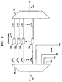
- FIG. 1 shows a block diagram of an illustrative embodiment of a WADM arrangement for selectively adding/dropping/substituting optical channels from an optical multiplexed signal in accordance with the principles of the present invention.
- An input waveguide 102 typically an optical fiber, serves as the input of the WADM arrangement.
- the input supplies an optical multiplexed signal, for example an N channel wavelength division multiplexed signal, to a first optical router 104.
- Optical router 104 has 2N output optical waveguides that form two sets of N waveguides each.
- the first set includes N waveguides 106 1 - 106 N
- the second duplicate set of waveguides includes waveguides 108 1 - 108 N .
- each waveguide set is known collectively as waveguides 106 and 108 respectively, and the arrangement is said to have a duplicated plurality of waveguides.
- a second optical router 110 has 2N input optical waveguides, waveguides 112 1 - 112 N , and a duplicate set of waveguides 114 1 - 114 N .
- each waveguide set is known collectively as waveguides 112 and 114 respectively.
- respective pairs of waveguides 106 and 108 and waveguides 112 and 114 have substantially identical spectral characteristics (for example, waveguide 106 1 propagates a substantially equivalent wavelength (e.g., ⁇ 1 ) as waveguide 108 1 ).
- Waveguides 106 and 112 interconnect optical router 104 to WGR 110. As shown in FIG. 1, waveguides 108 of optical router 104 drop channels at a particular network node and waveguides 114 of optical router 110 can add channels at the particular network node. Lastly, output waveguide 116 serves as an output of the WADM arrangement.
- Attenuator-switches 120 1 - 120 n are attenuator-switches 120 1 - 120 n , hereinafter known collectively as attenuator-switches 120.
- the attenuator-switches are optical shutters, which are described in more detail below.
- an attenuator-switch When open, permits any optical signal exiting an output waveguide 106 of optical router 104 to pass through to an input waveguide 112 of optical router 110 with minimum loss.
- an attenuator-switch absorbs or reflects, desirably with high efficiency, an incident optical channel preventing the channel from reaching optical router 110.
- Lead 118 receives a control signal from a source (not shown) to open and close the attenuator-switches 120.
- the control signal may be generated by any conventional means including, but not limited to: 1) local control, such as a central office network control operator; 2) remote control, such as a network control center, 3) automated through the use of dynamic network reconfiguration software; or 4) manual control.
- an optical multiplexed signal is directed to the WADM arrangement of FIG.1, wherein: (1) channels of the multiplexed signal may be dropped, (2) new channels, absent from the original optical multiplexed signal, may be added, (3) channels may be replaced by other channels which have the same carrier frequency channel, but which contain a different modulated signal, or (4) the channels may pass through substantially unchanged.
- FIG. 2 illustrates the manner in which an exemplary optical multiplexed signal (represented by and includes the following channels ⁇ 1 ⁇ 2 ⁇ 4 ... ⁇ n ) is affected by each optical router and the optical shutters (It is to be understood that the optical multiplexed input signal may or may not contain all channels of an N channel optical network).
- the optical multiplexed signal is first demultiplexed in optical router 104.
- each channel present in the multiplexed signal is propagated in respective pairs of waveguides 106 and 108.
- channel ⁇ 1 is present in the optical multiplexed input signal and is propagated in respective pairs of input waveguides 106 and 108, namely 106 1 and 108 1 .
- channel ⁇ 3 is not present in the optical multiplexed input signal. Therefore, a channel is not propagated in input waveguides 106 3 and 108 3 , wherein a dash ("-") is used to indicate where no channel is present in a particular waveguide.
- a dash is used to indicate where no channel is present in a particular waveguide.
- each attenuator-switch 120 is configured in one of two states, namely opened or closed, corresponding to channels that will be passed through unchanged or dropped.
- attenuator-switch 120 1 is configured in an open state (represented by horizontal lines in FIG. 2), thus channel ⁇ 1 is passed through to waveguide 112 1 of optical router 110.
- Attenuator-switch 120 2 is configured in a closed state (represented by vertical lines in FIG. 2), thus channel ⁇ 2 is absorbed and thereby prevented from reaching waveguide 112 2 of optical router 110.
- waveguides corresponding to channel components not present, for example ⁇ 3 in the optical multiplexed input signal can be configured in either state.
- Waveguides 114 are used to input channels, for example, as shown in FIG. 2, channels ⁇ ' 2 and ⁇ ' 3 are input to the WADM arrangement using waveguides 114 2 and 114 3 of optical router 110 (as above, a dash is used to indicate that no channel is being added, e.g., waveguides 114 1 and 114 4 ). Thereafter, the optical channels propagating within waveguides 114 and 112 are multiplexed in optical router 110 to produce a new optical multiplexed signal ⁇ 1 ⁇ ' 2 ⁇ ' 3 ... ⁇ N .
- FIG. 3 shows another illustrative embodiment for selectively dropping optical channels, which includes all of elements of the WADM arrangement shown and described in FIG. 1 except that the arrangement includes only one duplicated-port waveguide grating router (DWGR) 104.
- the other optical router is a conventional waveguide grating router (WGR) 310 (i.e. the ports are not duplicated).
- WGR 104 is configured as a 1 X 2N demultiplexer, which demultiplexes an optical multiplexed signal into a duplicated plurality of channels.
- WGR 310 is configured as an N X 1 multiplexer.
- the channels propagating in input waveguides 112 1 through 112 N are multiplexed by WGR 310.
- This embodiment illustrates the "drop and continue” functionality, wherein channels are both dropped at a particular node and may also continue to further nodes in an optical network.
- FIG. 4 shows another illustrative embodiment for selectively adding/substituting optical channels, which again includes all of elements of the WADM arrangement shown and described in FIG. 1 except, as in FIG. 3, the arrangement includes only one duplicated-port waveguide grating router (DWGR) 110.
- the other optical router is a conventional waveguide grating router (WGR) 404 (i.e. the ports are not duplicated).
- WGR 404 is configured as a 1 X N demultiplexer, which demultiplexes an optical multiplexed signal into a single plurality of channels.
- DWGR 110 is configured as a 2N X 1 multiplexer.
- the optical routers 104 and 110 of FIGS. 1 through 4 can be any known optical router (also commonly known as a frequency routing device) that has duplicated input or output ports.
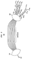
- FIG. 5 shows one type of optical router that can be used.
- the optical router of FIG.5 is described in US patent application Serial No. /19409463 filed concurrently.
- the optical router of FIG. 5 is a duplicated-port waveguide grating router (DWGR) and can be used as a 1 X 2N demultiplexer or as a 2N X 1 multiplexer, which correspond to optical router 104 and optical router 110 of FIGS. 1 through 4, respectively.
- DWGR duplicated-port waveguide grating router
- the use of the particular optical router described in the indicated application is particularly advantageous since the optical router provides duplicated (input or output) waveguides with substantially identical, largely flat passband spectral responses.
- the optical router of FIG. 5 when used as a 1 X 2N demultiplexer, the optical router includes an input waveguide 502, a first free space region 504, an optical grating 506, a second free space region 508, a plurality of output waveguides 510 1 through 510 N (hereinafter known collectively as output waveguides 510) and a plurality of 2X2 couplers 512 1 through 512 M , (hereinafter known collectively as 2X2 couplers 512) with each coupler having two output waveguides, for example, 514 11 and 514 12 (hereinafter known collectively as output ports 514).
- Each 2X2 coupler couples two adjacent output waveguides 510 to produce substantially identical spectral responses in each of the respective output ports 514.
- Each coupler may be, for example, an evanescent coupler, multi-mode interference coupler, star coupler or the like, in which the coupler has two input ports and two output ports.
- waveguide grating routers have reciprocal properties, when the waveguide grating router of FIG. 5 is used as a 2N X 1 multiplexer, the waveguide grating router would be operated in reverse and the output ports 514 of 2X2 couplers 512 would serve as the input waveguides and the input waveguide 502 as the output port of the waveguide grating router.
- the WADM arrangement of the present invention achieves full add/drop as well as drop and continue capability without unnecessary additional elements as taught in the prior art.
- a drop and continue WADM apparatus was implemented with external 3dB fiber couplers (at the expense of increased through-loss of the WADM).
- the attenuator-switches 120 are optical shutters, for example, micro-electromechanical system (MEMS) optical shutters.
- MEMS micro-electromechanical system
- the optical shutters could also be integrated with the optical routers as thermo-optic switches (as wall as flip-chip bonded MEMS optical shutters).
- arrays of optical shutters could be separately packaged and connected through optical fibers to the optical routers.
- the shutter is designed to completely reflect incident light. Alternatively, it is feasible, when desired, to move the shutter only enough so that some light is transmitted and some light is reflected to be extracted in a suitable manner for transfer to an auxiliary waveguide.
- the shutter may be made to redirect the reflected light either into alternative waveguides or back into source waveguides.
- some optical shutters could be made to both transmit and reflect, with an equivalent effect.
- MEMS devices can be used as variable optical attenuators with analog control to equalize or vary the desired signal level of individual channels as desired.
- MEMS is a technology that exploits lithographic mass fabrication techniques of the kind that are used by the semiconductor industry in the manufacture of silicon integrated circuits.
- the technology involves forming a multilayer structure by sequentially depositing and shaping layers on a silicon substrate. Layers typically include a plurality of polysilicon layers that are separated by layers of silicon oxide and silicon nitride.
- the shaping of individual layers is generally done by photolithographic techniques of the kind involved in silicon device manufacture.
- the technology may also involve the etching of intermediate sacrificial layers of the wafer to release overlying layers for use as flexible elements that can be easily moved.
- MEMS technology is discussed in a paper entitled "MEMS the Word for Optical Beam Manipulation" published in Circuits and Devices , July 1997, pp. 11 - 18.
- MEMS devices can be made to order by the MCNC MEMS Technology Application Center, Research Triangle Park, NC 27709.
- the technology is described in "Multiuser MEMS Processes (MUMPS) Introduction and Design Rules," Rev. 4, 7/15/96 MCNC MEMS Technology Applications Center, Research Triangle Park. NC 27709 by D. Keoster et al.
- the WADM arrangement is able to provide both a drop and continue and conventional add/drop functionality, without certain limitations of the prior art.
- the WADM arrangement of the present invention is able to eliminate elements, namely optical switches,, used in conventional WADM configurations that contribute significant cost within optical networks.
Landscapes
- Physics & Mathematics (AREA)
- Engineering & Computer Science (AREA)
- General Physics & Mathematics (AREA)
- Optics & Photonics (AREA)
- Microelectronics & Electronic Packaging (AREA)
- Computer Networks & Wireless Communication (AREA)
- Signal Processing (AREA)
- Optical Integrated Circuits (AREA)
- Optical Communication System (AREA)
- Mechanical Light Control Or Optical Switches (AREA)
- Optical Modulation, Optical Deflection, Nonlinear Optics, Optical Demodulation, Optical Logic Elements (AREA)
- Use Of Switch Circuits For Exchanges And Methods Of Control Of Multiplex Exchanges (AREA)
Abstract
Description
- This invention relates to an optical wavelength division multiplexing (WDM) add/drop arrangement.
- In a long-haul, high-capacity wavelength division multiplexing (WDM) optical network, the capability to remove and replace selective WDM wavelengths at multiple add/drop nodes across the network is essential for a variety of value-added communication services. Such communication services include local access, interactive multimedia and wavelength leasing. In particular, this capability requires adding or dropping one or more optical wavelengths (also known as channels) at each add/drop network node from a multiwavelength-multiplexed signal as well as substituting one or more optical wavelengths with new optical wavelengths.
- WDM add/drop systems have been disclosed in the prior art. Such systems have been constructed by pairing two waveguide grating routers (WGR), the first a 1XN wavelength demultiplexer and the second a NX1 passive wavelength combiner or multiplexer. In addition, an array of optical switches operate on a subset of the N wavelength interconnections between these two WGRs to remove, add and replace selective optical wavelengths (a system of this sort is disclosed in U.S. Patent No. 5,526,153, entitled "Optical Channel Adding/Dropping Filter, issued to Glance on June 11, 1996). In such a system, a multiwavelength-multiplexed signal is first demultiplexed, in the first WGR (e.g., the demultiplexer) to yield a multiplicity of individual optical wavelengths. Thereafter, a subset of the demultiplexed optical wavelengths is directed to the optical switches where either a drop, add, or a drop and add of one or more of the individual optical wavelengths takes place. Subsequently, the individual wavelengths are directed to the second WGR (e.g., the multiplexer) to produce a new multiwavelength-multiplexed signal. The optical multiplexers and demultiplexers used in such add/drop systems are further described in U.S. Patent No. 5,002,350, entitled "Optical Multiplexer/Demultiplexer', and U.S. Patent No. 5,136,671, entitled "Optical Switch, Multiplexer, and Demultiplexer" both issued to Dragone on March 26, 1991 and August 4, 1992, respectively.
- Although such WDM add/drop systems are effective for dropping and adding wavelengths, they add significant cost to optical networks since they require an array of expensive optical switches. With increased market competition and heightened customer expectations, it has become important to develop a low-cost WDM add/drop system.
- An optical wavelength division add/drop multiplexer (WADM) arrangement in accordance with the principles of the present invention includes a pair of optical routers, such as waveguide grating routers (WGRs), wherein at least one of the optical routers includes a duplicated plurality of input or output waveguides. Certain waveguides associated with each optical router are coupled together and at least one attenuator-switch, such as a micro-electromechanical system (MEMS) optical shutter, is interconnected between the coupled waveguides.
- In one illustrative embodiment, the WADM arrangement includes two duplicated-port waveguide grating routers (DWGR) and a plurality of optical shutters. The first DWGR is configured as a 1 X 2N demultiplexer, which demultiplexes an optical multiplexed signal into a duplicated plurality of channels. The other DWGR is configured as a
2N X 1 multiplexer. Each DWGR includes a duplicated plurality of input or output waveguides, wherein respective pairs of each duplicated plurality of waveguides have substantially identical spectral filtering characteristics. The first plurality of output waveguides of the first DWGR, which are coupled to the first plurality of input waveguides of the second DWGR, propagate one of the duplicated plurality of channels. Optical shutters are inserted between respective waveguides of these two pluralities of waveguides and can be used to block or reflect incident optical wavelengths corresponding to channels to be terminated at the node where the WADM arrangement is provided. The second plurality of output waveguides in the first DWGR propagate the other duplicated plurality of channels and drop these channels at the node where the WADM arrangement is provided. Lastly, the second plurality of input waveguides in the second DWGR are for adding channels to provide full add/drop capability. Once all of the appropriate adds/drops are accomplished, the channels propagating in the first and second input waveguides are multiplexed by the second DWGR. Thus, in addition to conventional add/drop capability, the WADM arrangement has a so-called "drop and continue" functionality, wherein channels are both dropped at a particular node and may also continue to further nodes in an optical network. - In contrast with the prior art, the present invention, by virtue of the DWGRs and a unique configuration, achieves add/drop as well as drop and continue functionality while reducing the cost of conventional WADM nodes in optical networks. The optical switches used in typical WADM nodes are not needed; the optical shutters that are present in this invention are much less expensive.
- The invention will be more fully understood from the following detailed description of an illustrative embodiment taken in conjunction with the appended figures in which:
- FIG. 1 shows a block diagram of an illustrative embodiment of the WADM arrangement in accordance with the principles of the present invention for selectively adding/dropping optical channels;
- FIG. 2 shows a block diagram of one exemplary configuration of the embodiment of FIG. 1 selectively adding/dropping/substituting optical channels;
- FIG. 3 shows a block diagram of an exemplary configuration of the present invention for selectively dropping optical channels;
- FIG. 4 shows a block diagram of one exemplary configuration of the present invention for selectively adding/substituting optical channels; and
- FIG. 5 shows a schematic diagram of an exemplary WGR used in the embodiment of FIG. 1.
-
- FIG. 1 shows a block diagram of an illustrative embodiment of a WADM arrangement for selectively adding/dropping/substituting optical channels from an optical multiplexed signal in accordance with the principles of the present invention. An
input waveguide 102, typically an optical fiber, serves as the input of the WADM arrangement. The input supplies an optical multiplexed signal, for example an N channel wavelength division multiplexed signal, to a firstoptical router 104.Optical router 104 has 2N output optical waveguides that form two sets of N waveguides each. The first set includes N waveguides 1061 - 106N, and the second duplicate set of waveguides includes waveguides 1081 - 108N. Hereinafter each waveguide set is known collectively as waveguides 106 and 108 respectively, and the arrangement is said to have a duplicated plurality of waveguides. A secondoptical router 110 has 2N input optical waveguides, waveguides 1121 - 112N, and a duplicate set of waveguides 1141 - 114N. Hereinafter each waveguide set is known collectively aswaveguides 112 and 114 respectively. As will be described in more detail below, respective pairs of waveguides 106 and 108 andwaveguides 112 and 114 have substantially identical spectral characteristics (for example, waveguide 1061 propagates a substantially equivalent wavelength (e.g., λ1) as waveguide 1081). Waveguides 106 and 112 interconnectoptical router 104 to WGR 110. As shown in FIG. 1, waveguides 108 ofoptical router 104 drop channels at a particular network node andwaveguides 114 ofoptical router 110 can add channels at the particular network node. Lastly,output waveguide 116 serves as an output of the WADM arrangement. - Between respective pairs of waveguides 106 and waveguides 112 of the input and output optical routers and along the wave path are attenuator-switches 1201 - 120n, hereinafter known collectively as attenuator-switches 120. In a preferred embodiment, the attenuator-switches are optical shutters, which are described in more detail below. When open, an attenuator-switch permits any optical signal exiting an output waveguide 106 of
optical router 104 to pass through to an input waveguide 112 ofoptical router 110 with minimum loss. When closed, an attenuator-switch absorbs or reflects, desirably with high efficiency, an incident optical channel preventing the channel from reachingoptical router 110.Lead 118 receives a control signal from a source (not shown) to open and close the attenuator-switches 120. As will be understood by persons skilled in the art, the control signal may be generated by any conventional means including, but not limited to: 1) local control, such as a central office network control operator; 2) remote control, such as a network control center, 3) automated through the use of dynamic network reconfiguration software; or 4) manual control. - Operationally, an optical multiplexed signal is directed to the WADM arrangement of FIG.1, wherein: (1) channels of the multiplexed signal may be dropped, (2) new channels, absent from the original optical multiplexed signal, may be added, (3) channels may be replaced by other channels which have the same carrier frequency channel, but which contain a different modulated signal, or (4) the channels may pass through substantially unchanged.
- FIG. 2 illustrates the manner in which an exemplary optical multiplexed signal (represented by and includes the following channels λ1λ2λ4... λn) is affected by each optical router and the optical shutters (It is to be understood that the optical multiplexed input signal may or may not contain all channels of an N channel optical network). In this illustrative embodiment, the optical multiplexed signal is first demultiplexed in
optical router 104. As shown in FIG. 2, each channel present in the multiplexed signal is propagated in respective pairs of waveguides 106 and 108. For example, channel λ1 is present in the optical multiplexed input signal and is propagated in respective pairs of input waveguides 106 and 108, namely 1061 and 1081. Moreover, channel λ3 is not present in the optical multiplexed input signal. Therefore, a channel is not propagated in input waveguides 1063 and 1083, wherein a dash ("-") is used to indicate where no channel is present in a particular waveguide. By using waveguides 106 and 108 in this manner, the so-called drop and continue function is implemented in the WADM arrangement because all of the channels are simultaneously dropped (using waveguides 108) at a particular network node and may continue (using waveguides 106) to further network nodes in an optical network. - Responsive to a control signal received by
lead 118, each attenuator-switch 120 is configured in one of two states, namely opened or closed, corresponding to channels that will be passed through unchanged or dropped. For example, attenuator-switch 1201 is configured in an open state (represented by horizontal lines in FIG. 2), thus channel λ1 is passed through to waveguide 1121 ofoptical router 110. Attenuator-switch 1202, however, is configured in a closed state (represented by vertical lines in FIG. 2), thus channel λ2 is absorbed and thereby prevented from reaching waveguide 1122 ofoptical router 110. Lastly, waveguides corresponding to channel components not present, for example λ3, in the optical multiplexed input signal can be configured in either state. -
Waveguides 114 are used to input channels, for example, as shown in FIG. 2, channels λ'2 and λ'3 are input to the WADMarrangement using waveguides waveguides 1141 and 1144). Thereafter, the optical channels propagating withinwaveguides 114 and 112 are multiplexed inoptical router 110 to produce a new optical multiplexed signal λ1 λ'2λ'3... λN. - FIG. 3 shows another illustrative embodiment for selectively dropping optical channels, which includes all of elements of the WADM arrangement shown and described in FIG. 1 except that the arrangement includes only one duplicated-port waveguide grating router (DWGR) 104. The other optical router is a conventional waveguide grating router (WGR) 310 (i.e. the ports are not duplicated).
DWGR 104 is configured as a 1 X 2N demultiplexer, which demultiplexes an optical multiplexed signal into a duplicated plurality of channels.WGR 310 is configured as anN X 1 multiplexer. Once all of the appropriate drops are accomplished, in a similar manner as described with regard to the operation of the embodiment of FIG. 1, the channels propagating in input waveguides 1121 through 112N are multiplexed byWGR 310. This embodiment illustrates the "drop and continue" functionality, wherein channels are both dropped at a particular node and may also continue to further nodes in an optical network. - FIG. 4 shows another illustrative embodiment for selectively adding/substituting optical channels, which again includes all of elements of the WADM arrangement shown and described in FIG. 1 except, as in FIG. 3, the arrangement includes only one duplicated-port waveguide grating router (DWGR) 110. The other optical router is a conventional waveguide grating router (WGR) 404 (i.e. the ports are not duplicated).
WGR 404 is configured as a 1 X N demultiplexer, which demultiplexes an optical multiplexed signal into a single plurality of channels.DWGR 110 is configured as a2N X 1 multiplexer. Once all of the appropriate adds/substitutions are accomplished, in a manner similar as described with regard to the operation of the embodiment of FIG. 1, the channels propagating in input waveguides 1121 through 112N and 1141 through 114N are multiplexed byDWGR 110. This embodiment illustrates the adding/substituting functionality. - The
optical routers - The optical router of FIG. 5 is a duplicated-port waveguide grating router (DWGR) and can be used as a 1 X 2N demultiplexer or as a
2N X 1 multiplexer, which correspond tooptical router 104 andoptical router 110 of FIGS. 1 through 4, respectively. The use of the particular optical router described in the indicated application is particularly advantageous since the optical router provides duplicated (input or output) waveguides with substantially identical, largely flat passband spectral responses. - Briefly, when the optical router of FIG. 5 is used as a 1 X 2N demultiplexer, the optical router includes an
input waveguide 502, a firstfree space region 504, anoptical grating 506, a secondfree space region 508, a plurality ofoutput waveguides 5101 through 510N (hereinafter known collectively as output waveguides 510) and a plurality of 2X2 couplers 5121 through 512M, (hereinafter known collectively as 2X2 couplers 512) with each coupler having two output waveguides, for example, 51411 and 51412 (hereinafter known collectively as output ports 514). Each 2X2 coupler couples twoadjacent output waveguides 510 to produce substantially identical spectral responses in each of the respective output ports 514. Each coupler may be, for example, an evanescent coupler, multi-mode interference coupler, star coupler or the like, in which the coupler has two input ports and two output ports. - Since waveguide grating routers have reciprocal properties, when the waveguide grating router of FIG. 5 is used as a
2N X 1 multiplexer, the waveguide grating router would be operated in reverse and the output ports 514 of 2X2 couplers 512 would serve as the input waveguides and theinput waveguide 502 as the output port of the waveguide grating router. - By using the optical router of FIG. 5, the WADM arrangement of the present invention achieves full add/drop as well as drop and continue capability without unnecessary additional elements as taught in the prior art. For example, as described in an article written by C.R. Giles et al., entitled "Reconfigurable 16-Channel WDM DROP Module Using Silicon MEMS Optical Switches" published in Photonics Technology Letters Vol. 11, NO. 1 on January, 1999, a drop and continue WADM apparatus was implemented with external 3dB fiber couplers (at the expense of increased through-loss of the WADM).
- Referring now to the other elements in FIGS. 1 - 4, advantageously, in a preferred embodiment, the attenuator-switches 120 are optical shutters, for example, micro-electromechanical system (MEMS) optical shutters. The optical shutters could also be integrated with the optical routers as thermo-optic switches (as wall as flip-chip bonded MEMS optical shutters). Alternatively, arrays of optical shutters could be separately packaged and connected through optical fibers to the optical routers. The shutter is designed to completely reflect incident light. Alternatively, it is feasible, when desired, to move the shutter only enough so that some light is transmitted and some light is reflected to be extracted in a suitable manner for transfer to an auxiliary waveguide. For example, the shutter may be made to redirect the reflected light either into alternative waveguides or back into source waveguides. Alternatively, some optical shutters could be made to both transmit and reflect, with an equivalent effect. Additionally, MEMS devices can be used as variable optical attenuators with analog control to equalize or vary the desired signal level of individual channels as desired.
- MEMS is a technology that exploits lithographic mass fabrication techniques of the kind that are used by the semiconductor industry in the manufacture of silicon integrated circuits. Generally, the technology involves forming a multilayer structure by sequentially depositing and shaping layers on a silicon substrate. Layers typically include a plurality of polysilicon layers that are separated by layers of silicon oxide and silicon nitride. The shaping of individual layers is generally done by photolithographic techniques of the kind involved in silicon device manufacture. The technology may also involve the etching of intermediate sacrificial layers of the wafer to release overlying layers for use as flexible elements that can be easily moved. MEMS technology is discussed in a paper entitled "MEMS the Word for Optical Beam Manipulation" published in Circuits and Devices, July 1997, pp. 11 - 18.
- MEMS devices can be made to order by the MCNC MEMS Technology Application Center, Research Triangle Park, NC 27709. The technology is described in "Multiuser MEMS Processes (MUMPS) Introduction and Design Rules," Rev. 4, 7/15/96 MCNC MEMS Technology Applications Center, Research Triangle Park. NC 27709 by D. Keoster et al.
- Using a duplicated-port optical router and a unique configuration, the WADM arrangement is able to provide both a drop and continue and conventional add/drop functionality, without certain limitations of the prior art. In addition, the WADM arrangement of the present invention is able to eliminate elements, namely optical switches,, used in conventional WADM configurations that contribute significant cost within optical networks.
- The exemplary embodiment of the invention described above is but one of a number of alternative embodiments of the invention that will be apparent to those skilled in the art in view of the foregoing description. Accordingly, this description is to be construed as illustrative only, and is for the purpose of teaching those skilled in the art the best mode of carrying out the invention. Various other alternatives can be devised by a person skilled in the art without departing from the teachings of this invention.
Claims (12)
- An add/drop optical multiplexing arrangement for dropping at least one channel of an optical multiplexed signal, the arrangement including:a first optical router having a duplicated plurality of output waveguides, said first optical router for demultiplexing said optical multiplexed signal, wherein a first one of said duplicated plurality of output waveguides is used for dropping said at least one channel;a second optical router having a first plurality of input waveguides, wherein respective waveguides of said first plurality of input waveguides are coupled to respective waveguides of a second one of said duplicated plurality of output waveguides, said second optical router for multiplexing channels in said first plurality of input waveguides; andat least one optical attenuator switch connected between one of said coupled waveguides, said at least one optical attenuator switch responsive to a control signal for preventing a channel of said first plurality of channels from reaching said first plurality of input waveguides when said optical attenuator switch is configured in a closed state.
- The add/drop optical multiplexing arrangement of claim 1 further for adding at least one channel to said optical multiplexed signal, wherein said second optical router further includes a second plurality of input waveguides for adding channels, said second plurality of input waveguides is a duplicate of said first plurality of input waveguides; and
wherein said second optical router multiplexes channels in said first and second plurality of input waveguides. - The add/drop optical multiplexing arrangement of claim 1, wherein respective pairs of said duplicated plurality of output waveguides of said first optical router have substantially identical spectral filtering characteristics.
- The add/drop optical multiplexing arrangement of claim 2, wherein respective pairs of said first and second plurality of input waveguides of said second optical router have substantially identical spectral filtering characteristics.
- The add/drop optical multiplexing arrangement of claim 1, wherein said first and second optical routers are waveguide grating routers.
- The add/drop optical multiplexing arrangement of claim 2, wherein said second plurality of input waveguides adds a channel to said add/drop optical multiplexing arrangement corresponding to a channel absent from said optical multiplexed signal.
- The add/drop optical multiplexing arrangement of claim 4, wherein said at least one optical attenuator switch prevents a channel from reaching said first plurality of input waveguides and said second plurality of input waveguides adds another channel having a carrier frequency substantially equal to, and a modulation different from, the channel prevented from reaching said first plurality of input waveguides,
- The add/drop optical multiplexing arrangement of claim 5, wherein said at least one optical attenuator switch is an optical shutter.
- The add/drop optical multiplexing arrangement of claim 8, wherein the at least one optical shutter is a micro-electromechanical system optical shutter (MEMS).
- The add/drop optical multiplexing arrangement of claim 5, wherein the at least one optical shutter is integrated with the first and second optical routers as a thermo-optic switch.
- A. method for adding at least one channel to a multiplexed optical signal, the method comprising the steps of:demultiplexing, in a first optical router having a first plurality of output waveguides, said multiplexed optical signal;configuring at least one optical attenuator switch to a closed or an open state, said at least one optical attenuator switch both for preventing a channel of said first plurality of channels from reaching a first plurality of input waveguides of a second optical router when said optical attenuator switch is configured in a closed state and for allowing said channel to propagate to said first plurality of input waveguides when said optical attenuator switch is configured in an open state;adding at least one channel using a second plurality of input waveguides of said second optical router andmultiplexing, in said second optical router, channels in said first and second plurality of input waveguides.
- The method of claim 11 further for dropping at least one channel of said optical multiplexed signal, said method further including the step of dropping at least one channel, wherein said first optical router further includes a second plurality of output waveguides for dropping said at least one channel, said second plurality of output waveguides is a duplicate of said first plurality of output waveguides; and
wherein said first optical router demultiplexes said optical multiplexed signal.
Applications Claiming Priority (2)
| Application Number | Priority Date | Filing Date | Title |
|---|---|---|---|
| US09/408,932 US6519059B1 (en) | 1999-09-30 | 1999-09-30 | Wavelength division add/drop multiplexer |
| US408932 | 1999-09-30 |
Publications (3)
| Publication Number | Publication Date |
|---|---|
| EP1089479A2 true EP1089479A2 (en) | 2001-04-04 |
| EP1089479A3 EP1089479A3 (en) | 2005-09-28 |
| EP1089479B1 EP1089479B1 (en) | 2015-03-11 |
Family
ID=23618367
Family Applications (1)
| Application Number | Title | Priority Date | Filing Date |
|---|---|---|---|
| EP00308091.8A Expired - Lifetime EP1089479B1 (en) | 1999-09-30 | 2000-09-18 | Wavelength division add/drop multiplexer |
Country Status (3)
| Country | Link |
|---|---|
| US (1) | US6519059B1 (en) |
| EP (1) | EP1089479B1 (en) |
| JP (1) | JP4388681B2 (en) |
Cited By (4)
| Publication number | Priority date | Publication date | Assignee | Title |
|---|---|---|---|---|
| WO2003017548A1 (en) * | 2001-08-17 | 2003-02-27 | Bookham Technology Plc | Modular optical system |
| US7860396B2 (en) | 2002-01-04 | 2010-12-28 | Ericsson Ab | Noise reduction in optical communications networks |
| EP1841277A3 (en) * | 2006-03-27 | 2013-06-12 | Oclaro (North America), Inc. | Multiport switch for an optical performance monitor |
| US20130223796A1 (en) * | 2012-02-29 | 2013-08-29 | Electronics And Telecommunications Research Institute | Arrayed wavelength grating router (awgr) for wavelength multiplexing and demultiplexing |
Families Citing this family (9)
| Publication number | Priority date | Publication date | Assignee | Title |
|---|---|---|---|---|
| US6721509B2 (en) * | 2000-12-05 | 2004-04-13 | Avanex Corporation | Self-adjusting optical add-drop multiplexer and optical networks using same |
| US6690848B2 (en) * | 2001-06-29 | 2004-02-10 | Nortel Networks Limited | Metropolitan photonic switch |
| US7171067B2 (en) * | 2003-03-03 | 2007-01-30 | Lucent Technologies Inc. | Integrateable optical interleaver and de-interleaver |
| US7424223B1 (en) * | 2003-08-04 | 2008-09-09 | Ciena Corporation | Reconfigurable wavelength blocking apparatus and optical selector device therefore |
| US20050226620A1 (en) * | 2004-04-05 | 2005-10-13 | Feuer Mark D | Four-port wavelength-selective crossbar switches (4WCS) using reciprocal WDM mux-demux and optical circulator combination |
| WO2012154958A1 (en) | 2011-05-10 | 2012-11-15 | Invensys Systems, Inc. | Multi-drop optical communication |
| CN103797737B (en) * | 2011-06-20 | 2017-02-15 | 普莱克希公司 | Optical architecture and channel plan employing multi-fiber configurations for data center network switching |
| US9450815B2 (en) * | 2013-07-11 | 2016-09-20 | Plexxi Inc. | Network node connection configuration |
| US11733468B2 (en) | 2021-12-08 | 2023-08-22 | Viavi Solutions Inc. | Photonic structure using optical heater |
Citations (2)
| Publication number | Priority date | Publication date | Assignee | Title |
|---|---|---|---|---|
| US5612805A (en) | 1994-06-07 | 1997-03-18 | Alcatel Cit | Add-drop optical spectrum-division multiplexer |
| US5930016A (en) | 1996-10-10 | 1999-07-27 | Tellabs Operations, Inc. | Upgradable modular wavelength division multiplexer |
Family Cites Families (9)
| Publication number | Priority date | Publication date | Assignee | Title |
|---|---|---|---|---|
| US5002350A (en) * | 1990-02-26 | 1991-03-26 | At&T Bell Laboratories | Optical multiplexer/demultiplexer |
| US5136671A (en) * | 1991-08-21 | 1992-08-04 | At&T Bell Laboratories | Optical switch, multiplexer, and demultiplexer |
| EP0651529B1 (en) * | 1993-10-29 | 2004-06-23 | Siemens Aktiengesellschaft | Optical transparent ring network with dropping of one wavelength signal in one or more ring nodes |
| US5526153A (en) * | 1994-01-21 | 1996-06-11 | At&T Corp. | Optical channel adding/dropping filter |
| US5566014A (en) * | 1994-12-28 | 1996-10-15 | At&T Corp. | Tunable add/drop optical filter providing arbitrary channel arrangements |
| JPH11239100A (en) * | 1998-02-20 | 1999-08-31 | Fujitsu Ltd | Optical wavelength multiplexing system with redundant configuration |
| KR100400362B1 (en) * | 1998-08-04 | 2003-11-14 | 삼성전자주식회사 | Apparatus for optical add drop multiplexing and WDM optical network comprising it |
| US6236781B1 (en) * | 1999-09-30 | 2001-05-22 | Agere Systems Optoelectronics Guardian Corp. | Duplicated-port waveguide grating router having substantially flat passbands |
| US6429974B1 (en) * | 2000-05-12 | 2002-08-06 | Mahi Networks | Add-drop multiplexer |
-
1999
- 1999-09-30 US US09/408,932 patent/US6519059B1/en not_active Expired - Lifetime
-
2000
- 2000-09-18 EP EP00308091.8A patent/EP1089479B1/en not_active Expired - Lifetime
- 2000-09-29 JP JP2000298175A patent/JP4388681B2/en not_active Expired - Fee Related
Patent Citations (2)
| Publication number | Priority date | Publication date | Assignee | Title |
|---|---|---|---|---|
| US5612805A (en) | 1994-06-07 | 1997-03-18 | Alcatel Cit | Add-drop optical spectrum-division multiplexer |
| US5930016A (en) | 1996-10-10 | 1999-07-27 | Tellabs Operations, Inc. | Upgradable modular wavelength division multiplexer |
Cited By (4)
| Publication number | Priority date | Publication date | Assignee | Title |
|---|---|---|---|---|
| WO2003017548A1 (en) * | 2001-08-17 | 2003-02-27 | Bookham Technology Plc | Modular optical system |
| US7860396B2 (en) | 2002-01-04 | 2010-12-28 | Ericsson Ab | Noise reduction in optical communications networks |
| EP1841277A3 (en) * | 2006-03-27 | 2013-06-12 | Oclaro (North America), Inc. | Multiport switch for an optical performance monitor |
| US20130223796A1 (en) * | 2012-02-29 | 2013-08-29 | Electronics And Telecommunications Research Institute | Arrayed wavelength grating router (awgr) for wavelength multiplexing and demultiplexing |
Also Published As
| Publication number | Publication date |
|---|---|
| US6519059B1 (en) | 2003-02-11 |
| JP4388681B2 (en) | 2009-12-24 |
| EP1089479B1 (en) | 2015-03-11 |
| JP2001156716A (en) | 2001-06-08 |
| EP1089479A3 (en) | 2005-09-28 |
Similar Documents
| Publication | Publication Date | Title |
|---|---|---|
| US6614953B2 (en) | Modular all-optical cross-connect | |
| US6148124A (en) | Wavelength division multiplexed optical networks | |
| US6631222B1 (en) | Reconfigurable optical switch | |
| EP0985289B1 (en) | Optical multiplexing and demultiplexing | |
| JP2001112034A (en) | Cross connection exchange and its realization method | |
| US20050281558A1 (en) | Flexible band tunable add/drop multiplexer and modular optical node architecture | |
| JPH08254720A (en) | Tunable add / drop optical filter to provide arbitrary channel arrangement | |
| US6519059B1 (en) | Wavelength division add/drop multiplexer | |
| US7437075B2 (en) | Integrated reconfigurable optical add/drop multiplexer | |
| US6956987B2 (en) | Planar lightwave wavelength blocker devices using micromachines | |
| JP2007148042A (en) | Wavelength selective optical switch, optical combiner, optical branching device, and wavelength selective optical switch module | |
| Pu et al. | Client-configurable eight-channel optical add/drop multiplexer using micromachining technology | |
| EP1116346B1 (en) | Tuneable add/drop multiplexer | |
| US7257285B2 (en) | Wavelength-selective switch and integrated wavelength demultiplexer using stacked planar lightwave circuits | |
| US7113662B2 (en) | Optical filtering by using an add-drop node | |
| JPH11271559A (en) | Optical device | |
| US20030081888A1 (en) | Integrated wavelength router | |
| US6950571B1 (en) | Optical switchable component | |
| Pu et al. | Micro-machined optical add/drop multiplexer with client configurability | |
| Earnshaw et al. | A colorless wavelength add or drop module with ultralow power consumption | |
| WO2002098038A1 (en) | Integrated optical add-drop multiplexer (oadm) using optical waveguide mirrors and multiplexer/demultiplexer |
Legal Events
| Date | Code | Title | Description |
|---|---|---|---|
| PUAI | Public reference made under article 153(3) epc to a published international application that has entered the european phase |
Free format text: ORIGINAL CODE: 0009012 |
|
| AK | Designated contracting states |
Kind code of ref document: A2 Designated state(s): AT BE CH CY DE DK ES FI FR GB GR IE IT LI LU MC NL PT SE |
|
| AX | Request for extension of the european patent |
Free format text: AL;LT;LV;MK;RO;SI |
|
| PUAL | Search report despatched |
Free format text: ORIGINAL CODE: 0009013 |
|
| AK | Designated contracting states |
Kind code of ref document: A3 Designated state(s): AT BE CH CY DE DK ES FI FR GB GR IE IT LI LU MC NL PT SE |
|
| AX | Request for extension of the european patent |
Extension state: AL LT LV MK RO SI |
|
| 17P | Request for examination filed |
Effective date: 20060321 |
|
| AKX | Designation fees paid |
Designated state(s): DE FR GB IT |
|
| 17Q | First examination report despatched |
Effective date: 20061229 |
|
| RAP3 | Party data changed (applicant data changed or rights of an application transferred) |
Owner name: LUCENT TECHNOLOGIES INC. |
|
| RAP1 | Party data changed (applicant data changed or rights of an application transferred) |
Owner name: ALCATEL-LUCENT USA INC. |
|
| 111Z | Information provided on other rights and legal means of execution |
Free format text: DE FR GB IT Effective date: 20130410 |
|
| GRAP | Despatch of communication of intention to grant a patent |
Free format text: ORIGINAL CODE: EPIDOSNIGR1 |
|
| RIC1 | Information provided on ipc code assigned before grant |
Ipc: G02B 6/12 20060101ALI20140409BHEP Ipc: G02B 6/293 20060101ALI20140409BHEP Ipc: H04J 14/02 20060101AFI20140409BHEP |
|
| INTG | Intention to grant announced |
Effective date: 20140430 |
|
| RAP1 | Party data changed (applicant data changed or rights of an application transferred) |
Owner name: ALCATEL LUCENT |
|
| GRAP | Despatch of communication of intention to grant a patent |
Free format text: ORIGINAL CODE: EPIDOSNIGR1 |
|
| GRAJ | Information related to disapproval of communication of intention to grant by the applicant or resumption of examination proceedings by the epo deleted |
Free format text: ORIGINAL CODE: EPIDOSDIGR1 |
|
| GRAP | Despatch of communication of intention to grant a patent |
Free format text: ORIGINAL CODE: EPIDOSNIGR1 |
|
| INTG | Intention to grant announced |
Effective date: 20141015 |
|
| D11X | Information provided on other rights and legal means of execution (deleted) | ||
| INTG | Intention to grant announced |
Effective date: 20141024 |
|
| GRAS | Grant fee paid |
Free format text: ORIGINAL CODE: EPIDOSNIGR3 |
|
| GRAL | Information related to payment of fee for publishing/printing deleted |
Free format text: ORIGINAL CODE: EPIDOSDIGR3 |
|
| GRAS | Grant fee paid |
Free format text: ORIGINAL CODE: EPIDOSNIGR3 |
|
| GRAA | (expected) grant |
Free format text: ORIGINAL CODE: 0009210 |
|
| AK | Designated contracting states |
Kind code of ref document: B1 Designated state(s): DE FR GB IT |
|
| REG | Reference to a national code |
Ref country code: GB Ref legal event code: FG4D |
|
| REG | Reference to a national code |
Ref country code: DE Ref legal event code: R096 Ref document number: 60048891 Country of ref document: DE Effective date: 20150423 |
|
| REG | Reference to a national code |
Ref country code: FR Ref legal event code: PLFP Year of fee payment: 16 |
|
| REG | Reference to a national code |
Ref country code: DE Ref legal event code: R097 Ref document number: 60048891 Country of ref document: DE |
|
| PG25 | Lapsed in a contracting state [announced via postgrant information from national office to epo] |
Ref country code: IT Free format text: LAPSE BECAUSE OF FAILURE TO SUBMIT A TRANSLATION OF THE DESCRIPTION OR TO PAY THE FEE WITHIN THE PRESCRIBED TIME-LIMIT Effective date: 20150311 |
|
| PLBE | No opposition filed within time limit |
Free format text: ORIGINAL CODE: 0009261 |
|
| STAA | Information on the status of an ep patent application or granted ep patent |
Free format text: STATUS: NO OPPOSITION FILED WITHIN TIME LIMIT |
|
| 26N | No opposition filed |
Effective date: 20151214 |
|
| REG | Reference to a national code |
Ref country code: FR Ref legal event code: PLFP Year of fee payment: 17 |
|
| PGFP | Annual fee paid to national office [announced via postgrant information from national office to epo] |
Ref country code: DE Payment date: 20160921 Year of fee payment: 17 Ref country code: GB Payment date: 20160920 Year of fee payment: 17 |
|
| PGFP | Annual fee paid to national office [announced via postgrant information from national office to epo] |
Ref country code: FR Payment date: 20160921 Year of fee payment: 17 |
|
| REG | Reference to a national code |
Ref country code: DE Ref legal event code: R119 Ref document number: 60048891 Country of ref document: DE |
|
| GBPC | Gb: european patent ceased through non-payment of renewal fee |
Effective date: 20170918 |
|
| REG | Reference to a national code |
Ref country code: FR Ref legal event code: ST Effective date: 20180531 |
|
| PG25 | Lapsed in a contracting state [announced via postgrant information from national office to epo] |
Ref country code: GB Free format text: LAPSE BECAUSE OF NON-PAYMENT OF DUE FEES Effective date: 20170918 Ref country code: DE Free format text: LAPSE BECAUSE OF NON-PAYMENT OF DUE FEES Effective date: 20180404 |
|
| PG25 | Lapsed in a contracting state [announced via postgrant information from national office to epo] |
Ref country code: FR Free format text: LAPSE BECAUSE OF NON-PAYMENT OF DUE FEES Effective date: 20171002 |