EP1089323A1 - Lamp with fuse - Google Patents
Lamp with fuse Download PDFInfo
- Publication number
- EP1089323A1 EP1089323A1 EP00308541A EP00308541A EP1089323A1 EP 1089323 A1 EP1089323 A1 EP 1089323A1 EP 00308541 A EP00308541 A EP 00308541A EP 00308541 A EP00308541 A EP 00308541A EP 1089323 A1 EP1089323 A1 EP 1089323A1
- Authority
- EP
- European Patent Office
- Prior art keywords
- flare
- leads
- lamp
- envelope
- arc
- Prior art date
- Legal status (The legal status is an assumption and is not a legal conclusion. Google has not performed a legal analysis and makes no representation as to the accuracy of the status listed.)
- Withdrawn
Links
- 239000000463 material Substances 0.000 claims abstract description 23
- 238000010791 quenching Methods 0.000 claims abstract description 20
- 239000011324 bead Substances 0.000 claims abstract description 18
- 239000000945 filler Substances 0.000 claims abstract description 13
- 239000011521 glass Substances 0.000 claims abstract description 13
- 238000000034 method Methods 0.000 claims description 20
- VYPSYNLAJGMNEJ-UHFFFAOYSA-N Silicium dioxide Chemical compound O=[Si]=O VYPSYNLAJGMNEJ-UHFFFAOYSA-N 0.000 claims description 10
- 238000007789 sealing Methods 0.000 claims description 9
- 230000000171 quenching effect Effects 0.000 claims description 5
- 239000004576 sand Substances 0.000 claims description 3
- 239000006004 Quartz sand Substances 0.000 claims description 2
- 229910052602 gypsum Inorganic materials 0.000 claims description 2
- 239000010440 gypsum Substances 0.000 claims description 2
- 239000000377 silicon dioxide Substances 0.000 claims description 2
- WFKWXMTUELFFGS-UHFFFAOYSA-N tungsten Chemical compound [W] WFKWXMTUELFFGS-UHFFFAOYSA-N 0.000 abstract description 2
- 229910052721 tungsten Inorganic materials 0.000 abstract description 2
- 239000010937 tungsten Substances 0.000 abstract description 2
- 239000000565 sealant Substances 0.000 abstract 1
- PXHVJJICTQNCMI-UHFFFAOYSA-N Nickel Chemical compound [Ni] PXHVJJICTQNCMI-UHFFFAOYSA-N 0.000 description 8
- XKRFYHLGVUSROY-UHFFFAOYSA-N Argon Chemical compound [Ar] XKRFYHLGVUSROY-UHFFFAOYSA-N 0.000 description 6
- 238000004519 manufacturing process Methods 0.000 description 5
- IJGRMHOSHXDMSA-UHFFFAOYSA-N Atomic nitrogen Chemical compound N#N IJGRMHOSHXDMSA-UHFFFAOYSA-N 0.000 description 4
- 230000006378 damage Effects 0.000 description 4
- 239000002245 particle Substances 0.000 description 4
- 229910000792 Monel Inorganic materials 0.000 description 3
- 208000027418 Wounds and injury Diseases 0.000 description 3
- 229910052786 argon Inorganic materials 0.000 description 3
- 229910052736 halogen Inorganic materials 0.000 description 3
- 150000002367 halogens Chemical class 0.000 description 3
- 239000000155 melt Substances 0.000 description 3
- 239000000203 mixture Substances 0.000 description 3
- 229910052759 nickel Inorganic materials 0.000 description 3
- RYGMFSIKBFXOCR-UHFFFAOYSA-N Copper Chemical compound [Cu] RYGMFSIKBFXOCR-UHFFFAOYSA-N 0.000 description 2
- 229910000990 Ni alloy Inorganic materials 0.000 description 2
- 230000015572 biosynthetic process Effects 0.000 description 2
- 229910052802 copper Inorganic materials 0.000 description 2
- 239000010949 copper Substances 0.000 description 2
- 239000007788 liquid Substances 0.000 description 2
- 238000002844 melting Methods 0.000 description 2
- 230000008018 melting Effects 0.000 description 2
- 229910052751 metal Inorganic materials 0.000 description 2
- 239000002184 metal Substances 0.000 description 2
- 229910052757 nitrogen Inorganic materials 0.000 description 2
- OKTJSMMVPCPJKN-UHFFFAOYSA-N Carbon Chemical compound [C] OKTJSMMVPCPJKN-UHFFFAOYSA-N 0.000 description 1
- 229910000881 Cu alloy Inorganic materials 0.000 description 1
- 229910000934 Monel 400 Inorganic materials 0.000 description 1
- VEQPNABPJHWNSG-UHFFFAOYSA-N Nickel(2+) Chemical compound [Ni+2] VEQPNABPJHWNSG-UHFFFAOYSA-N 0.000 description 1
- NINIDFKCEFEMDL-UHFFFAOYSA-N Sulfur Chemical compound [S] NINIDFKCEFEMDL-UHFFFAOYSA-N 0.000 description 1
- 239000000956 alloy Substances 0.000 description 1
- 229910045601 alloy Inorganic materials 0.000 description 1
- 229910052799 carbon Inorganic materials 0.000 description 1
- 239000004568 cement Substances 0.000 description 1
- 239000008119 colloidal silica Substances 0.000 description 1
- OANFWJQPUHQWDL-UHFFFAOYSA-N copper iron manganese nickel Chemical compound [Mn].[Fe].[Ni].[Cu] OANFWJQPUHQWDL-UHFFFAOYSA-N 0.000 description 1
- 238000002242 deionisation method Methods 0.000 description 1
- 238000010891 electric arc Methods 0.000 description 1
- 229920006332 epoxy adhesive Polymers 0.000 description 1
- 238000010438 heat treatment Methods 0.000 description 1
- 239000011261 inert gas Substances 0.000 description 1
- 208000014674 injury Diseases 0.000 description 1
- 229910052743 krypton Inorganic materials 0.000 description 1
- DNNSSWSSYDEUBZ-UHFFFAOYSA-N krypton atom Chemical compound [Kr] DNNSSWSSYDEUBZ-UHFFFAOYSA-N 0.000 description 1
- WPBNNNQJVZRUHP-UHFFFAOYSA-L manganese(2+);methyl n-[[2-(methoxycarbonylcarbamothioylamino)phenyl]carbamothioyl]carbamate;n-[2-(sulfidocarbothioylamino)ethyl]carbamodithioate Chemical compound [Mn+2].[S-]C(=S)NCCNC([S-])=S.COC(=O)NC(=S)NC1=CC=CC=C1NC(=S)NC(=O)OC WPBNNNQJVZRUHP-UHFFFAOYSA-L 0.000 description 1
- 238000003825 pressing Methods 0.000 description 1
- 239000003566 sealing material Substances 0.000 description 1
- 239000004590 silicone sealant Substances 0.000 description 1
- 229910052709 silver Inorganic materials 0.000 description 1
- 239000004332 silver Substances 0.000 description 1
- 229910052717 sulfur Inorganic materials 0.000 description 1
- 239000011593 sulfur Substances 0.000 description 1
- 229910052724 xenon Inorganic materials 0.000 description 1
- FHNFHKCVQCLJFQ-UHFFFAOYSA-N xenon atom Chemical compound [Xe] FHNFHKCVQCLJFQ-UHFFFAOYSA-N 0.000 description 1
Images

Classifications
-
- H—ELECTRICITY
- H01—ELECTRIC ELEMENTS
- H01K—ELECTRIC INCANDESCENT LAMPS
- H01K1/00—Details
- H01K1/62—One or more circuit elements structurally associated with the lamp
- H01K1/66—One or more circuit elements structurally associated with the lamp with built-in fuse
-
- H—ELECTRICITY
- H01—ELECTRIC ELEMENTS
- H01J—ELECTRIC DISCHARGE TUBES OR DISCHARGE LAMPS
- H01J61/00—Gas-discharge or vapour-discharge lamps
- H01J61/02—Details
- H01J61/56—One or more circuit elements structurally associated with the lamp
Definitions
- This invention relates to the lamp arts and, more particularly, to an electric lamp, which incorporates a Ballotini-type fuse into the flare.
- fuses are often used to interrupt excessive current flow to protect the lamp from damaging electric arcing.
- the fuses are typically formed from a strip of metal or alloy, such as Monel or nickel D wire.
- Monel or nickel D wire a strip of metal or alloy, such as Monel or nickel D wire.
- one or more internal arcs can develop. These arcs can melt a hole through the lamp base or weld the base to the lamp socket, with a resultant risk of fire and personal injury.
- the current flow during arcing may result in rupturing of the filament tube, and resultant damage to the outer envelope of the lamp.
- a present method of reducing arcing is to incorporate a commercially available Ballotini fuse as stand-alone component in the lamp.
- a Ballotini fuse consists of a smaller diameter tube (typically 2-3 millimeters in diameter) filled with glass beads or other arc-quenching material.
- a fuse wire is centered inside the glass bead-filled tube. When excessive current activates the fuse, the fuse wire melts and the arc is extinguished rapidly by the glass beads. The time of arcing is significantly reduced as compared with a fuse without the beads.
- the delivered current and the energy flowing into the lamp during arcing are much lower than without the beads, reducing the potential damage.
- the use of a Ballotini fuse requires separate manufacturing of the component and complicates the lamp assembly process.
- the present invention provides a new and improved lamp and method of formation, which overcomes the above-referenced problems and others.
- a lamp in an exemplary embodiment of the present invention is provided.
- the lamp includes a light transmitting envelope and an energizable light source within the envelope.
- a flare extends into the envelope, the flare including an interior cavity.
- Leads are provided for connecting the energizable light source with a source of power.
- the leads extend through the flare cavity. A portion of at least one of the leads comprises a fusible element.
- An arc-quenching filler is disposed in the interior cavity around the at least one fusible element.
- a flare for a lamp in another exemplary embodiment of the present invention, includes a hollow tubular portion, which defines an interior cavity.
- An exhaust tube extends through the interior cavity to define a space between the tubular portion and the exhaust tube.
- Leads are provided for connecting an energizable light source with a source of power.
- the leads extend through the space in the flare interior cavity.
- a portion of at least one of the leads comprises a fusible element.
- a first end of the tubular portion is sealed around the exhaust tube and the leads and closes off the first end of the interior cavity.
- An arc-quenching filler is disposed in the space in the flare interior cavity around the at least one fusible element.
- a method of forming a lamp includes providing a hollow tube with a first open end and a second open end and positioning an exhaust tube within the hollow tube to define an annular space between the exhaust tube and the hollow tube. The method further includes positioning leads through the annular space, at least one of the leads including a fusible element. Further, the method includes sealing the first end of the hollow tube to close off a first end of the annular space, ends of the leads extending through the sealed first end. An arc quenching material is disposed around the fusible element within the annular space.
- One advantage of the present invention is that arcing and lamp damage is minimized.
- Another advantage of the present invention is that manufacture of the lamp is simplified.
- an incandescent lamp 10 has a light transmitting, glass envelope 12 secured to a base 14.
- the envelope shown in FIGURE 1 has a bulbous upper portion 16 and a narrower, generally cylindrical lower portion 18, although other envelope geometries are also contemplated. It should be appreciated that the terms “upper” and “lower”, “above” and “below”, and the like, refer to the lamp as shown in FIGURE 1, in which the base is shown extending below the envelope.
- the base includes a metal shell 20, an insulative plug 22 and a standard contact 24.
- Four-part connecting leads 26 are used to connect a source of power (not shown) with an energizable light source 28, such as a coiled filament of tungsten, positioned within the bulbous portion 16 of the envelope.
- the four part leads include support leads 30 and 32, such as nickel or nickel-plated copper wires, which connect with and support the light source 28.
- a filament tube (not shown) may surround the filament, as in the case of an incandescent halogen lamp. Other light sources are also contemplated.
- a generally cylindrical, flare or reentrant stem mount 40 is seated within the envelope.
- the flare is sealed around a lower end 42 thereof to the bottom periphery of the cylindrical portion 18 of the envelope.
- An exhaust tube 46 extends axially through the flare and is sealed off at a lower end of the tube to hermetically seal the envelope, which contains an inert gas, such as a mixture of nitrogen and argon, or may be evacuated.
- Each support lead 30, 32 connects with an intermediate wire segment 50, 52, respectively, formed, for example, from DUMET wire, which extends through and is sealed into a press-on portion 54 of the flare 40.
- the press-on portion seals around the upper end of each of the intermediate wire segments and the lower ends of the support leads 30, 32 and the upper end of the exhaust tube.
- a hollow portion or generally annular cavity 58 is thus formed within the flare, between the flare 40 and the exhaust tube 46.
- the wire segments 50, 52 extend at their lower ends into the cavity 58 of the flare, where they are connected with respective fusible elements, such as fuse wires 60, 62 of, for example, Monel or other nickel alloy, such as nickel 211.
- Monel is a nickel/copper alloy.
- a preferred fuse wire is formed from Monel 400, having a composition of 63-70% nickel, and maximums of 0.3% carbon, 2.0% manganese, 0.24% sulfur, and 0.5% silver, the remainder copper. Other materials, which melt on application of an excess current, may also be used for the fusible material.
- the fuse wires are connected at their lower ends, within the hollow portion 58, to outer leads 70, 72, which in turn are connected to the center contact 24 and the upper rim of the shell 20, respectively, as shown in FIGURE 1.
- the flare cavity 58 is filled with an arc-quenching filler material 76.
- an electric arc being generated (generally as a result of one of the fuses melting when excess current passes) the filler material 76 rapidly extinguishes the arc.
- the arc-quenching material melts and vaporizes in the arc, causing deionization of the arc space.
- the filler material is preferably in the form of particles and is not electrically conductive.
- the material preferably also has a low thermal conductivity. Suitable arc-quenching materials include glass beads, silica sand, quartz sand, gypsum, chalk, other known arc-quenching filler materials, and combinations thereof.
- the beads, or other arcquenching materials preferably surround the fuses and are closely packed in the cavity.
- the material may be of the bound filler type, in which sand particles are bound together by, for example, colloidal silica particles. Without the beads, the time of arcing is significantly longer.
- the fuse wires 60, 62 are wound around a core (not shown).
- the core may be a supporting core or a core formed from a frozen mixture of arc-quenching material and liquid. The fuse wound core is then surrounded by additional arc-quenching material. The frozen core, if used, is melted prior to use and the liquid evaporated.
- Either one or both of the leads 26 can include fuse wires.
- both the leads contain a fuse wire section 60, 62 for best results.
- the fuse wire 60, 62 melts and the arc is extinguished rapidly by the glass beads, or other arc-quenching material. Without the glass beads, the time of the arcing is typically about 5 milliseconds. Adding the beads reduces the arcing to about 2 milliseconds.
- the four part leads 26, each comprising support lead 30,32, connecting lead 50, 52, fuse wire 60, 62 and outer lead 70,72 are inserted into a first open, upper end 80 of the flare and the exhaust tube 46 is axially aligned in the flare 40, as shown in FIGURE 3.
- the upper end 80 of the flare is hermetically sealed around the connecting leads by heating and pressing the glass at 54, as shown in FIGURE 2.
- the flare is then sealed around its lower end 42 to the envelope 12, as shown in FIGURE 4.
- the envelope is evacuated via the exhaust tube 46 and the nitrogen/argon (or krypton or xenon in place of argon) fill, if used, loaded into the envelope 12 through the exhaust tube, or the envelope is evacuated, in the case of an evacuated envelope.
- a lower end 82 of the exhaust tube is then "tipped off,” to hermetically seal the fill or vacuum in the envelope, as shown in FIGURE 5. Mechanical sealing or melting of the glass can be used.
- the glass beads 76, or other particles, are inserted into the flare cavity 58 via an open end 84 thereof to surround the fuse wires 60,62, as shown in FIGURE 5.
- the lower end 84 of the cavity is sealed by a seal 86, for example, an epoxy adhesive, a silicone sealant, such as RTV, or other sealing material, best shown in FIGURE 2.
- the seal formed need not be a hermetic seal but is sufficient to retain the beads 76 in the cavity 58.
- the base 14 is attached to the connecting leads 70,72 and attached to the lower end of the bulb to complete the lamp forming process.
- the beads are inserted into the flare cavity, around the fuses, prior to sealing the flare to the envelope.
- the fill is inserted into the envelope and the bottom end of the exhaust tube sealed off as previously described.
- the first method is preferred over this method because it allows the flare to be integrally formed with the envelope.
- Other methods of assembling the lamp are also contemplated.
- the flare with the incorporated Ballotini-type fuse according to FIGURES 1 and 2 can thus be manufactured as part of the lamp assembly process. This process is easily automated and eliminates the need for a specially manufactured Ballotini fuse.
Landscapes
- Vessels And Coating Films For Discharge Lamps (AREA)
- Fuses (AREA)
Abstract
A fuse for a lamp (10) is formed in a flare (40) of the
lamp. Leads (26) for an energizable light source (28),
such as a tungsten filament, pass through a cavity (58)
in the flare. A portion (60,62) of each lead within the
flare cavity is fusible. Arcing is dissipated by an
arc-quenching filler material (76), such as glass beads,
which fill the flare cavity and surround the fusible
portions. A sealant (86) retains the beads in the cavity.
Description
- This invention relates to the lamp arts and, more particularly, to an electric lamp, which incorporates a Ballotini-type fuse into the flare.
- In the manufacture of electric lamps, such as incandescent or halogen lamps, fuses are often used to interrupt excessive current flow to protect the lamp from damaging electric arcing. The fuses are typically formed from a strip of metal or alloy, such as Monel or nickel D wire. However, upon filament failure or fuse burnout, one or more internal arcs can develop. These arcs can melt a hole through the lamp base or weld the base to the lamp socket, with a resultant risk of fire and personal injury. In the case of a halogen filament tube, the current flow during arcing may result in rupturing of the filament tube, and resultant damage to the outer envelope of the lamp.
- To reduce such arcs, manufacturers have sometimes filled the lamp base with one or more insulative or porous cement layers in an attempt to insulate the inside conductive surface of the base from fuse wire arcing. This type of solution requires additional steps in lamp manufacturing and considerable expense. Further, although base melt-through is reduced, it continues to be a problem.
- Extinguishing the arc as fast as possible is therefore of primary importance. A present method of reducing arcing is to incorporate a commercially available Ballotini fuse as stand-alone component in the lamp. A Ballotini fuse consists of a smaller diameter tube (typically 2-3 millimeters in diameter) filled with glass beads or other arc-quenching material. A fuse wire is centered inside the glass bead-filled tube. When excessive current activates the fuse, the fuse wire melts and the arc is extinguished rapidly by the glass beads. The time of arcing is significantly reduced as compared with a fuse without the beads.
- Additionally, the delivered current and the energy flowing into the lamp during arcing are much lower than without the beads, reducing the potential damage. However, the use of a Ballotini fuse requires separate manufacturing of the component and complicates the lamp assembly process.
- The present invention provides a new and improved lamp and method of formation, which overcomes the above-referenced problems and others.
- In an exemplary embodiment of the present invention a lamp is provided. The lamp includes a light transmitting envelope and an energizable light source within the envelope. A flare extends into the envelope, the flare including an interior cavity. Leads are provided for connecting the energizable light source with a source of power. The leads extend through the flare cavity. A portion of at least one of the leads comprises a fusible element.
- An arc-quenching filler is disposed in the interior cavity around the at least one fusible element.
- In another exemplary embodiment of the present invention, a flare for a lamp is provided. The flare includes a hollow tubular portion, which defines an interior cavity. An exhaust tube extends through the interior cavity to define a space between the tubular portion and the exhaust tube. Leads are provided for connecting an energizable light source with a source of power. The leads extend through the space in the flare interior cavity. A portion of at least one of the leads comprises a fusible element. A first end of the tubular portion is sealed around the exhaust tube and the leads and closes off the first end of the interior cavity. An arc-quenching filler is disposed in the space in the flare interior cavity around the at least one fusible element.
- In another exemplary embodiment of the present invention, a method of forming a lamp is provided. The method includes providing a hollow tube with a first open end and a second open end and positioning an exhaust tube within the hollow tube to define an annular space between the exhaust tube and the hollow tube. The method further includes positioning leads through the annular space, at least one of the leads including a fusible element. Further, the method includes sealing the first end of the hollow tube to close off a first end of the annular space, ends of the leads extending through the sealed first end. An arc quenching material is disposed around the fusible element within the annular space.
- One advantage of the present invention is that arcing and lamp damage is minimized.
- Another advantage of the present invention is that manufacture of the lamp is simplified.
- Still further advantages of the present invention will become apparent to those of ordinary skill in the art upon reading and understanding the following detailed description of the preferred embodiments.
- Embodiments of the invention will now be described, by way of example, with reference to the accompanying drawings, in which:-
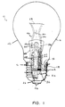
- FIGURE 1 is a front sectional view of a lamp in accordance with the present invention;
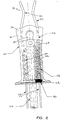
- FIGURE 2 is an enlarged sectional view of the flare with a Ballotini-type fuse of FIGURE 1;
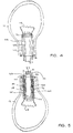
- FIGURE 3 is a side sectional view of a flare during formation of the lamp of FIGURE 1;
- FIGURE 4 is a side view of the flare of FIGURE 3 after sealing to a lamp envelope; and
- FIGURE 5 is a side view of the lamp envelope and flare of FIGURE 4 after tipping off the exhaust tube and filling the flare cavity with glass beads.
-
- With reference to FIGURES 1 and 2, an
incandescent lamp 10 has a light transmitting,glass envelope 12 secured to abase 14. The envelope shown in FIGURE 1 has a bulbousupper portion 16 and a narrower, generally cylindricallower portion 18, although other envelope geometries are also contemplated. It should be appreciated that the terms "upper" and "lower", "above" and "below", and the like, refer to the lamp as shown in FIGURE 1, in which the base is shown extending below the envelope. - The base includes a
metal shell 20, aninsulative plug 22 and astandard contact 24. Four-part connecting leads 26 are used to connect a source of power (not shown) with anenergizable light source 28, such as a coiled filament of tungsten, positioned within thebulbous portion 16 of the envelope. The four part leads include support leads 30 and 32, such as nickel or nickel-plated copper wires, which connect with and support thelight source 28. A filament tube (not shown) may surround the filament, as in the case of an incandescent halogen lamp. Other light sources are also contemplated. - A generally cylindrical, flare or
reentrant stem mount 40 is seated within the envelope. The flare is sealed around alower end 42 thereof to the bottom periphery of thecylindrical portion 18 of the envelope. Anexhaust tube 46 extends axially through the flare and is sealed off at a lower end of the tube to hermetically seal the envelope, which contains an inert gas, such as a mixture of nitrogen and argon, or may be evacuated. - Each support lead 30, 32 connects with an
intermediate wire segment portion 54 of theflare 40. The press-on portion seals around the upper end of each of the intermediate wire segments and the lower ends of the support leads 30, 32 and the upper end of the exhaust tube. A hollow portion or generallyannular cavity 58 is thus formed within the flare, between theflare 40 and theexhaust tube 46. - The
wire segments cavity 58 of the flare, where they are connected with respective fusible elements, such as
fuse wires
from Monel 400, having a composition of 63-70% nickel, and maximums of 0.3% carbon, 2.0% manganese, 0.24% sulfur, and 0.5% silver, the remainder copper. Other materials, which melt on application of an excess current, may also be used for the fusible material. - The fuse wires are connected at their lower ends, within the
hollow portion 58, toouter leads center contact 24 and the upper rim of theshell 20, respectively, as shown in FIGURE 1. - The
flare cavity 58 is filled with an arc-quenchingfiller material 76. In the event of an electric arc being generated (generally as a result of one of the fuses melting when excess current passes) thefiller material 76 rapidly extinguishes the arc. The arc-quenching material melts and vaporizes in the arc, causing deionization of the arc space. The filler material is preferably in the form of particles and is not electrically conductive. The material preferably also has a low thermal conductivity. Suitable arc-quenching materials include glass beads, silica sand, quartz sand, gypsum, chalk, other known arc-quenching filler materials, and combinations thereof. The beads, or other arcquenching materials, preferably surround the fuses and are closely packed in the cavity. The material may be of the bound filler type, in which sand particles are bound together by, for example, colloidal silica particles. Without the beads, the time of arcing is significantly longer. - Optionally, the
fuse wires - Either one or both of the
leads 26 can include fuse wires. In the preferred embodiment, both the leads contain afuse wire section - In the event of excessive passage of current, the
fuse wire - To form the lamp, the four part leads 26, each comprising
support lead lead fuse wire outer lead upper end 80 of the flare and theexhaust tube 46 is axially aligned in theflare 40, as shown in FIGURE 3. Theupper end 80 of the flare is hermetically sealed around the connecting leads by heating and pressing the glass at 54, as shown in FIGURE 2. The flare is then sealed around itslower end 42 to theenvelope 12, as shown in FIGURE 4. The envelope is evacuated via theexhaust tube 46 and the nitrogen/argon (or krypton or xenon in place of argon) fill, if used, loaded into theenvelope 12 through the exhaust tube, or the envelope is evacuated, in the case of an evacuated envelope. Alower end 82 of the exhaust tube is then "tipped off," to hermetically seal the fill or vacuum in the envelope, as shown in FIGURE 5. Mechanical sealing or melting of the glass can be used. - The
glass beads 76, or other particles, are inserted into theflare cavity 58 via anopen end 84 thereof to surround thefuse wires lower end 84 of the cavity is sealed by aseal 86, for example, an epoxy adhesive, a silicone sealant, such as RTV, or other sealing material, best shown in FIGURE 2. The seal formed need not be a hermetic seal but is sufficient to retain thebeads 76 in thecavity 58. Thebase 14 is attached to the connecting leads 70,72 and attached to the lower end of the bulb to complete the lamp forming process. - In an alternative method of production, the beads are inserted into the flare cavity, around the fuses, prior to sealing the flare to the envelope. The fill is inserted into the envelope and the bottom end of the exhaust tube sealed off as previously described. For most purposes, the first method is preferred over this method because it allows the flare to be integrally formed with the envelope. Other methods of assembling the lamp are also contemplated.
- The flare with the incorporated Ballotini-type fuse according to FIGURES 1 and 2 can thus be manufactured as part of the lamp assembly process. This process is easily automated and eliminates the need for a specially manufactured Ballotini fuse.
Claims (10)
- A lamp comprising: a light transmitting envelope;an energizable light source within the envelope;a flare extending into the envelope, the flare including an interior cavity;leads for electrically connecting the energizable light source with a source of power, the leads extending through the flare cavity, a portion of at least one of the leads comprising a fusible element;an arc-quenching filler disposed in the interior cavity around the at least one fusible element.
- The lamp of claim 1, wherein the arc-quenching filler comprises at least one of the group consisting of glass beads, silica sand, quartz sand, gypsum, chalk, and combinations thereof.
- The lamp of claim 1, further including a seal which holds the arc-quenching filler material within the flare.
- A flare for a lamp comprising:a hollow tubular portion which defines an interior cavity;an exhaust tube extending through the interior cavity, a space being defined between the tubular portion and the exhaust tube;leads for connecting an energizable light source with a source of power, the leads extending through the space in the flare interior cavity, a portion of at least one of the leads comprising a fusible element;a first end of the flare being sealed around the exhaust tube and the leads and closing off the first end of the interior cavity; andan arc-quenching filler disposed in the space in the flare interior cavity around the at least one fusible element.
- The flare of claim 4, further including a seal at a second end of the flare which holds the arcquenching filler material within the space in the flare interior cavity.
- A method of forming a lamp, the method comprising:providing a hollow tube with a first open end and a second open end; positioning an exhaust tube within the hollow tube to define an annular space between the exhaust tube and the hollow tube;positioning leads through the annular space, at least one of the leads including a fusible element;sealing the first end of the hollow tube to close off a first end of the annular space, ends of the leads extending through the sealed first end; anddisposing an arc quenching material around the fusible element within the annular space.
- The method of claim 6, further including:
sealing a second end of the annular space to retain the arc quenching material within the annular space. - The method of claim 6, further including:
sealing the hollow tube adjacent the second open end of the hollow tube to an envelope to define an interior space within the envelope which is accessed by the exhaust tube. - The method of claim 8, wherein the step of sealing the hollow tube adjacent the second open end of the hollow tube to the envelope is carried out prior to the step of disposing an arc quenching material around the fusible element within the flare.
- The method of claim 8, further including, prior to the step of disposing an arc quenching material around the fusible element within the flare:
sealing off an end of the exhaust tube to create a hermetically sealed space in the envelope around the light source.
Applications Claiming Priority (2)
| Application Number | Priority Date | Filing Date | Title |
|---|---|---|---|
| US40754099A | 1999-09-28 | 1999-09-28 | |
| US407540 | 1999-09-28 |
Publications (1)
| Publication Number | Publication Date |
|---|---|
| EP1089323A1 true EP1089323A1 (en) | 2001-04-04 |
Family
ID=23612513
Family Applications (1)
| Application Number | Title | Priority Date | Filing Date |
|---|---|---|---|
| EP00308541A Withdrawn EP1089323A1 (en) | 1999-09-28 | 2000-09-28 | Lamp with fuse |
Country Status (3)
| Country | Link |
|---|---|
| EP (1) | EP1089323A1 (en) |
| JP (1) | JP2001160378A (en) |
| CN (1) | CN1290026A (en) |
Families Citing this family (2)
| Publication number | Priority date | Publication date | Assignee | Title |
|---|---|---|---|---|
| JP5772753B2 (en) | 2012-07-30 | 2015-09-02 | トヨタ自動車株式会社 | Manufacturing method of secondary battery |
| CN110265284B (en) * | 2013-03-15 | 2021-11-05 | 应用材料公司 | Simplified luminaire design |
Citations (7)
| Publication number | Priority date | Publication date | Assignee | Title |
|---|---|---|---|---|
| US3767965A (en) * | 1972-03-01 | 1973-10-23 | Gen Electric | High intensity lamp containing internal shorting fuse |
| US4362969A (en) * | 1981-04-27 | 1982-12-07 | Gte Products Corporation | High intensity discharge lamp including arc extinguishing means |
| EP0131325A1 (en) * | 1983-06-29 | 1985-01-16 | Koninklijke Philips Electronics N.V. | Electric lamp |
| EP0168874A1 (en) * | 1984-07-03 | 1986-01-22 | Koninklijke Philips Electronics N.V. | Electric incandescent lamp |
| GB2207566A (en) * | 1987-07-24 | 1989-02-01 | Gen Electric Plc | Protective electric fuses |
| EP0441439A1 (en) * | 1990-02-08 | 1991-08-14 | Koninklijke Philips Electronics N.V. | Electric lamp |
| US5585693A (en) * | 1995-02-17 | 1996-12-17 | Osram Sylvania Inc. | Fluorescent lamp with end of life arc quenching structure |
-
2000
- 2000-09-27 JP JP2000293210A patent/JP2001160378A/en not_active Withdrawn
- 2000-09-28 EP EP00308541A patent/EP1089323A1/en not_active Withdrawn
- 2000-09-28 CN CN 00129266 patent/CN1290026A/en active Pending
Patent Citations (7)
| Publication number | Priority date | Publication date | Assignee | Title |
|---|---|---|---|---|
| US3767965A (en) * | 1972-03-01 | 1973-10-23 | Gen Electric | High intensity lamp containing internal shorting fuse |
| US4362969A (en) * | 1981-04-27 | 1982-12-07 | Gte Products Corporation | High intensity discharge lamp including arc extinguishing means |
| EP0131325A1 (en) * | 1983-06-29 | 1985-01-16 | Koninklijke Philips Electronics N.V. | Electric lamp |
| EP0168874A1 (en) * | 1984-07-03 | 1986-01-22 | Koninklijke Philips Electronics N.V. | Electric incandescent lamp |
| GB2207566A (en) * | 1987-07-24 | 1989-02-01 | Gen Electric Plc | Protective electric fuses |
| EP0441439A1 (en) * | 1990-02-08 | 1991-08-14 | Koninklijke Philips Electronics N.V. | Electric lamp |
| US5585693A (en) * | 1995-02-17 | 1996-12-17 | Osram Sylvania Inc. | Fluorescent lamp with end of life arc quenching structure |
Also Published As
| Publication number | Publication date |
|---|---|
| JP2001160378A (en) | 2001-06-12 |
| CN1290026A (en) | 2001-04-04 |
Similar Documents
| Publication | Publication Date | Title |
|---|---|---|
| EP0562871B1 (en) | Filament support for incandescent lamps | |
| JPH06203811A (en) | Lamp including tungsten - halogen light source | |
| CN1149197A (en) | Mercury-containing compact fluorescent lamps with improved warm-up characteristics | |
| US3448322A (en) | Direct filament enclosed incandescent lamps and contact means therefor | |
| JPH0719562B2 (en) | Light | |
| US3364378A (en) | Electric incandescent lamp unit built-in fuse | |
| US4495440A (en) | Arc-extinguishing ampul and fluorescent lamp having such ampul mounted on each electrode structure | |
| CN100437891C (en) | halogen incandescent lamp | |
| US4132922A (en) | Gas-filled incandescent lamp with integral fuse assembly | |
| US6720718B2 (en) | Thin walled lamp with tungsten halogen capsule and pyrophoric fuse | |
| EP1089323A1 (en) | Lamp with fuse | |
| US3767965A (en) | High intensity lamp containing internal shorting fuse | |
| JPH09167599A (en) | Double tube incandescent light bulb | |
| CN101213635A (en) | Ceramic lamp and method for manufacturing the same | |
| US4866340A (en) | Explosion resistant tungsten-halogen incandescent lamp | |
| US6774563B2 (en) | Support for a lamp capsule and end-of-life device, lamp including such capsule, and method of coupling lamp capsule and end-of-life device to such support | |
| EP0418877B1 (en) | Single-sealed metal vapor electric discharge lamp | |
| US4415836A (en) | Lamp with improved fuse wire | |
| CA1165800A (en) | Halogen incandescent lamp | |
| US4629939A (en) | Discharge lamp with automatic shut off | |
| EP0108449B1 (en) | Electric lamp | |
| US4382205A (en) | Metal vapor arc lamp having thermal link diminishable in heat conduction | |
| KR100712745B1 (en) | Electric lamp | |
| JP4498940B2 (en) | Metal halide lamp | |
| JPH0696746A (en) | Tubular bulb |
Legal Events
| Date | Code | Title | Description |
|---|---|---|---|
| PUAI | Public reference made under article 153(3) epc to a published international application that has entered the european phase |
Free format text: ORIGINAL CODE: 0009012 |
|
| AK | Designated contracting states |
Kind code of ref document: A1 Designated state(s): DE FR GB IT |
|
| AX | Request for extension of the european patent |
Free format text: AL;LT;LV;MK;RO;SI |
|
| 17P | Request for examination filed |
Effective date: 20011004 |
|
| AKX | Designation fees paid |
Free format text: DE FR GB IT |
|
| STAA | Information on the status of an ep patent application or granted ep patent |
Free format text: STATUS: THE APPLICATION HAS BEEN WITHDRAWN |
|
| 18W | Application withdrawn |
Effective date: 20030306 |