EP1089105A1 - Splittable optical fiber ribbons - Google Patents
Splittable optical fiber ribbons Download PDFInfo
- Publication number
- EP1089105A1 EP1089105A1 EP00402478A EP00402478A EP1089105A1 EP 1089105 A1 EP1089105 A1 EP 1089105A1 EP 00402478 A EP00402478 A EP 00402478A EP 00402478 A EP00402478 A EP 00402478A EP 1089105 A1 EP1089105 A1 EP 1089105A1
- Authority
- EP
- European Patent Office
- Prior art keywords
- sub
- unit
- edge
- ribbon
- optical fiber
- Prior art date
- Legal status (The legal status is an assumption and is not a legal conclusion. Google has not performed a legal analysis and makes no representation as to the accuracy of the status listed.)
- Granted
Links
- 239000013307 optical fiber Substances 0.000 title claims abstract description 135
- 230000000295 complement effect Effects 0.000 claims abstract description 4
- 239000011159 matrix material Substances 0.000 claims description 50
- 108010001267 Protein Subunits Proteins 0.000 claims description 8
- 238000004519 manufacturing process Methods 0.000 claims description 5
- 238000005538 encapsulation Methods 0.000 abstract description 6
- 238000000034 method Methods 0.000 description 17
- 230000008569 process Effects 0.000 description 13
- 230000007704 transition Effects 0.000 description 11
- 239000000835 fiber Substances 0.000 description 9
- 239000011347 resin Substances 0.000 description 9
- 229920005989 resin Polymers 0.000 description 9
- 230000000694 effects Effects 0.000 description 6
- 239000000463 material Substances 0.000 description 6
- 229920000642 polymer Polymers 0.000 description 4
- 230000002708 enhancing effect Effects 0.000 description 3
- 239000004925 Acrylic resin Substances 0.000 description 2
- 230000008901 benefit Effects 0.000 description 2
- 230000013011 mating Effects 0.000 description 2
- 239000004814 polyurethane Substances 0.000 description 2
- 229920002635 polyurethane Polymers 0.000 description 2
- 238000007493 shaping process Methods 0.000 description 2
- 239000012815 thermoplastic material Substances 0.000 description 2
- 239000004952 Polyamide Substances 0.000 description 1
- 239000004743 Polypropylene Substances 0.000 description 1
- 102000002067 Protein Subunits Human genes 0.000 description 1
- 230000015572 biosynthetic process Effects 0.000 description 1
- 229920001577 copolymer Polymers 0.000 description 1
- 238000010586 diagram Methods 0.000 description 1
- 238000010894 electron beam technology Methods 0.000 description 1
- 230000004927 fusion Effects 0.000 description 1
- 230000003993 interaction Effects 0.000 description 1
- 230000014759 maintenance of location Effects 0.000 description 1
- 238000012986 modification Methods 0.000 description 1
- 230000004048 modification Effects 0.000 description 1
- 229920002647 polyamide Polymers 0.000 description 1
- -1 polypropylene Polymers 0.000 description 1
- 229920001155 polypropylene Polymers 0.000 description 1
- 238000005096 rolling process Methods 0.000 description 1
Images


Classifications
-
- G—PHYSICS
- G02—OPTICS
- G02B—OPTICAL ELEMENTS, SYSTEMS OR APPARATUS
- G02B6/00—Light guides; Structural details of arrangements comprising light guides and other optical elements, e.g. couplings
- G02B6/44—Mechanical structures for providing tensile strength and external protection for fibres, e.g. optical transmission cables
- G02B6/4479—Manufacturing methods of optical cables
- G02B6/448—Ribbon cables
-
- G—PHYSICS
- G02—OPTICS
- G02B—OPTICAL ELEMENTS, SYSTEMS OR APPARATUS
- G02B6/00—Light guides; Structural details of arrangements comprising light guides and other optical elements, e.g. couplings
- G02B6/44—Mechanical structures for providing tensile strength and external protection for fibres, e.g. optical transmission cables
- G02B6/4401—Optical cables
- G02B6/4403—Optical cables with ribbon structure
- G02B6/4404—Multi-podded
Definitions
- the present invention relates to splittable optical fiber ribbons and, in particular, optical fiber ribbons for telecommunications cables. More particularly, the present invention is directed to the interface between adjacent sub-unit ribbons within splittable double-embedded optical fiber ribbons.
- Each sub-unit is formed of a plurality of optical fibers disposed in a plane and encapsulated with a polymer thereby forming the sub-unit.
- Each sub-unit includes rounded edges, which are placed adjacent one another, when the sub-units are arranged side-by-side so that the optical fibers of all the sub-units lie substantially in a plane.
- the sub-units are then encapsulated by a second polymer coat to form one optical fiber ribbon therefrom.
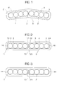
- a related-art sub-unit design, and ribbon made therefrom, are shown in Figure 1.
- a first sub-unit 1' includes optical fibers 3' encapsulated within a matrix material 4'.
- a second sub-unit 2' includes optical fibers 3' encapsulated within a matrix material 4'. Both of the first and second sub-units 1' and 2' have rounded edges.
- ribbon planarity is a measure of optical fiber alignment in a ribbon and is a measure of ribbon quality.
- Ribbon planarity plays an important part in fusion and mechanical multi-fiber splicing, as well as in termination in the field. Ribbon planarity is measured according to industry standards wherein a planarity of zero indicates that all fibers in the ribbon lie in the same plane. Therefore, it is desirable to achieve a ribbon planarity which is as low as possible.
- Figure 1 shows a ribbon having poor ⁇ i.e., high ⁇ planarity.
- the rotation of the two sub-unit ribbons is due, at least in part, to the surface tension effects occurring in the second matrix material as it is cured between or among sub-unit ribbons during the curing process.
- rotation of the sub-unit ribbons may be due to the fact that different ribbon sub-units may be under different pay-off and take-up tensions during the ribbonizing process.
- the sub-unit ribbons may have electrostatic forces and may be under vibration during ribbon processing due to the instability of the equipment. These factors may lead to ⁇ due to the point-contact between sub-units higher or inconsistent ribbon planarity.
- the planarity may be greater than 50 ⁇ m, which is too large for certain specifications ⁇ US GR-20-CORE, issue 2, Italy's Telecom Italia, and Swedish Telia, for example ⁇ depending on the fiber count in the ribbon.
- the ribbon sub-units include a minimum of two fibers and can include up to 12-fibers per sub-unit.
- a ribbon includes of a minimum of two ribbon sub-units and each sub-unit may include a different number of optical fibers.
- a ribbon may have three sub-units , wherein each sub-unit may include either 2, or 4, or 6, or 8, or 12, or any other number of, optical fibers.
- An object of the present invention is to overcome the problems of the related art.
- a further object of the present invention is to alleviate, or at the very least, minimize the related-art problem of poor ⁇ i.e., high ⁇ planarity in double-embedded optical fiber ribbons formed from sub-unit ribbons.
- Planarity in a double-embedded optical fiber ribbon is improved ⁇ i.e., lowered ⁇ in the present invention, by enhancing the stability of the interface between the sub-unit ribbons from which the double-embedded optical fiber ribbon is made.
- the present invention enhances interface stability by shaping the sub-unit-ribbon edges so as to create an interlocking effect and a greater contact area between the sub-units.
- the interlocking effect and greater contact area reduce sub-unit-ribbon interfacial micro-movement during formation of the double-embedded optical fiber ribbon.
- Interface stability may be enhanced by making the sub-unit ribbon edges of a complementary shape so as to create an interlocking effect.
- the edges may be complimentarily shaped by inclusion of a non-circular surface on one edge of each sub-unit.
- the non-circular surfaces when adjacent one another, reduce rotation or rolling motion of the sub-units about the interface, i.e., the non-circular surfaces tend to interlock the sub-unit ribbons.
- the edges of the sub-units, opposite those edges which include a non-circular surface may be either rounded or may also include a non-circular surface.
- a sub-unit ribbon wherein both edges include a non-circular surface is advantageous when producing a double-embedded optical fiber ribbon of more than two sub-units. That is, the double-embedded optical fiber ribbon may be made of any number of sub-units so that it includes the desired number of optical fibers. A sub-unit having only one edge that includes a non-circular surface is advantageously disposed on the edges of the double-embedded optical fiber ribbon.
- a sub-unit having one rounded edge and one edge that includes a non-circular surface can be arranged so that its rounded edge is disposed toward the outer edge of the double-embedded optical fiber, whereas the edge having a non-circular surface is disposed adjacent another sub-unit's non-circular surface.
- the non-circular surfaces may be included in variously shaped sub-unit edges, all of which enhance the stability of the interface between the sub-units by resisting relative rotation.
- the non-circular surfaces may be substantially perpendicular to the plane in which the sub-unit's optical fibers lie.
- the non-circular surface may be oblique to the plane in which the sub-unit's optical fibers lie.
- the non-circular surfaces may include protrusions extending therefrom. Not only do sub-units that have a non-circular surface on their edges enhance resistance to rotation, they are also complementarily shaped so as to provide an increased contact area between the sub-unit edges.
- the stability of the interface between sub-units can be increased using rounded edges that have an increased contact area therebetween. That is, one sub-unit may have an edge with a concave circular surface, whereas an adjacent sub-unit may then have a convex circular surface which fits within the concave circular surface.
- the circular or rounded edges of the present invention sub-units contact one another over a large portion of their complementarily rounded edges.
- the sub-units may be separated by the second matrix material, or may directly abut one another.
- edge shapes provide an interlocking effect, they also provide a greater contact area between the sub-units, thereby further enhancing stability of the sub-unit interface.
- a greater opposing surface area for limiting sub-unit rotation is achieved by the above-mentioned edge shapes. Further, when the sub-units are directly abutted, without any of the second matrix material therebetween, they are even less likely to rotate relative to one another.
- the sub-units when there is no second polymer coat between the sub-units, not only is planarity improved ⁇ i.e., lowered ⁇ and less second matrix material required but, also, the sub-units are more easily separated. That is, split-ability of the ribbon is enhanced because the sub-units are allowed to slide relative to one another along their contact interface when a splitting force is applied in a direction parallel to the contact surface. Although split-ability is enhanced, the sub-units still provide an increased resistance to relative rotation because the contact interface is less susceptible to surface tension forces arising from the outer matrix material during the curing process, and is less susceptible to other factors which cause relative rotation.
- the sub-unit ribbons may be formed using any known method.
- individual optical fibers are aligned in a common plane and fed through a die in which a matrix material is applied to form the sub-unit ribbon structure.
- the material for the matrix material in each sub-unit ribbon may be any of the conventionally used matrix materials.
- One wellknown matrix material used for optical fiber ribbons is a polyurethane acrylate resin. Such a resin material may be ultraviolet (UV) curable, so that after the optical fibers pass through a die and resin material is applied to form the matrix material over the optical fibers, each entire sub-unit structure is passed through a UV light source for curing the resin.
- UV ultraviolet
- the matrix material is selected from a group of materials which is strong, elastic, flexible, resistant to heat and other elements, etc.
- the matrix material may be a UV curable polyurethane acrylate resin as mentioned above, and as manufactured by DSM Desotech inc., Elgin, Il, USA.
- other commercially available resin materials such as DSM 900 series or BORDEN 100 series, for example, may be used as the matrix material, as is known to those skilled in the art.
- thermoplastic materials such as polypropylene or polyamide, or copolymers, for example, may be used as the matrix material. As is known to those skilled in the art, once the thermoplastic material is applied as the matrix material in a molten state, it is solidified by the removal of heat.
- the second matrix material of the double-embedded optical fiber ribbon may be any of the conventionally used matrix materials and may be the same as, or different from, the material used for the matrix material in the sub-unit ribbons.
- the sub-unit ribbons may be made by any known method
- the present invention contemplates a specially shaped die for making multiple sub-unit ribbons at one time, which sub-units are already properly aligned for encapsulation by a second matrix material. That is, it is preferable to make the sub-units and form them into a double-embedded optical fiber ribbon in a one-step process.
- the present invention is directed to improving ⁇ i.e., reducing ⁇ the planarity of a double-embedded optical fiber ribbon by enhancing the stability of the interface between the edges of sub-unit ribbons which make up the double-embedded optical fiber ribbon. Stability is enhanced by shaping the edges of the sub-unit ribbons so that they have an interlocking effect, and so that they also have an increased contact area therebetween.
- top, bottom, right, left, inner, and outer are used in connection with the orientation of the double-embedded optical fiber ribbons shown in the figures.
- the double-embedded optical fiber ribbons may be oriented in a manner different from that shown in the figures.
- the double-embedded optical fiber ribbon includes a first sub-unit ribbon 1 and a second sub-unit ribbon 2 which are disposed adjacent one another and are encapsulated in matrix material 5 which is also called an outer encapsulation layer.
- Each of the first and second sub-unit ribbons 1, 2 includes a plurality of optical fibers 3 which are arranged in a plane and then embedded in a matrix material 4.
- the first sub-unit ribbon 1 includes a first edge on which flat surface 10 is disposed, and a second edge on which a second flat surface 16 is disposed.
- the second sub-unit ribbon 2 includes a first edge on which flat surface 20 is disposed, and a second edge on which a second flat surface 26 is disposed.
- the flat surfaces 10, 20, 16, 26 are substantially perpendicular to the plane in which the optical fibers 3 lie.
- first sub-unit ribbon 1 includes transition regions 12 extending from the flat surface 10 to the top and bottom surfaces of the sub-unit 1, as well as includes transition regions 14 extending from the flat surface 26 to the sub-unit top and bottom surfaces.
- second sub-unit ribbon 2 includes transition regions 22 extending from the flat surface 20 to the top and bottom of the sub-unit 2, as well as includes transition regions 24 extending from the flat surface 26 to the sub-unit top and bottom surfaces.
- transition regions 12, 14, 22, 24 are shown as rounded, they may be of any other suitable shape.
- the first and second sub-unit ribbons 1, 2 are disposed adjacent one another so that the flat surface 10 faces the flat surface 20.
- the first and second sub-unit ribbons 1, 2 are then encapsulated by a second matrix material 5.
- the sub-unit ribbons 1, 2 may be disposed so that second matrix material 5 is disposed between the flat surfaces 10, 20 or, alternatively, may be disposed so that the flat surface 10 abuts the flat surface 20.
- the sub-units are less likely to rotate relative to one another, thereby improving planarity, due to the interaction of flat surfaces 10 and 20.
- the sub-unit ribbons are less likely to shift relative to one another ⁇ in a direction parallel to the flat surfaces 10, 20 ⁇ during production because of the direct contact.
- the directly abutting sub-units are more easily split from the double-embedded optical fiber ribbon because they can shift along their directly abutting surfaces.
- Figure 3 shows an alternative version of the outer edges of the sub-units shown in Figure 2.
- the first and second sub-unit ribbons 1, 2 are the same as in Figure 2, except the second ⁇ outer ⁇ edges are rounded, as at 18 and 28, respectively, instead of having flat surfaces 16, 26.
- the rounded outer edges 18, 28 are useful in a double-embedded optical fiber ribbon which includes two sub-units. Because of the rounded outer edges 18, 28, less matrix material 5 is required to encapsulate the sub-units 1, 2 and still provide smoothly rounded edges for the double-embedded optical fiber ribbon. In contrast, sub-units having outer edges with flat surfaces 16, 26 are preferred for forming a double-embedded optical fiber ribbon that includes more than two sub-units.
- the flat surfaces 16, 26 can be advantageously disposed adjacent to the flat surfaces of additional sub-units.
- the inner sub-units may be formed as are those shown in Figure 2
- the outer sub-units i.e., the sub-units on the outer edges of the double-embedded optical fiber ribbon, may be formed as are those shown in Figure 3.
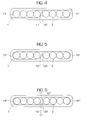
- Figures 4 and 5 show a second embodiment of the present invention which will now be described.
- the first sub-unit ribbon 1 includes an edge having a flat surface 10' that extends between the top and bottom surface of the sub-unit. Further, the flat surface 10' is disposed oblique to the plane which contains the optical fibers 3 of the sub-unit.
- the second sub-unit 2 includes a flat surface 20' that extends between the top and bottom surfaces of the sub-unit, and is disposed oblique to the plane containing that sub-unit's optical fibers 3. The sub-units are aligned so that the surface 10' opposes surface 20'.
- the first sub-unit ribbon 1 includes a second ⁇ outer ⁇ edge that includes a flat surface 16'
- the second sub-unit ribbon 2 includes a second ⁇ outer ⁇ edge that includes a flat surface 26'.
- the flat surfaces 16', 26' extend between the top and bottom surfaces of the sub-units 1, 2, and are oblique to the plane containing the optical fibers 3. Further, the flat surfaces 16', 26' are shown as being parallel to the flat surfaces 10', 20', respectively, although they do not necessarily have to be. However, when the flat surfaces 16', 26' are parallel to the surfaces 10', 20', more than two sub-unit ribbons may be disposed adjacent one another to form a double-embedded optical fiber ribbon.
- the outer edges of the sub-unit ribbons 1, 2 may be rounded as at 18', 28' shown in Figure 5.
- the outer-edge arrangement of Figure 5 enables the sub-unit ribbons to be encapsulated with less matrix material 5 than the outer-edge arrangement shown in Figure 4. Further, the outer-edge arrangement of Figure 5 has the added benefit of facilitating assembly of the double-embedded optical fiber ribbon by having only one way that the two sub-unit ribbons can be properly aligned, i.e., with their flat edges opposing or abutting one another.
- sub-unit ribbons of Figures 4 and 5 may be used in combination, in the same manner as the sub-unit ribbons of the first embodiment are used, to provide a double-embedded optical fiber ribbon having more than two sub-units.
- the surfaces 10', 20', 16', 26' are shown in Figures 4 and 5 as extending between the top and bottom surfaces of the sub-units 1, 2, respectively, transition regions of any shape may be used as in the first embodiment of the invention.
- the surfaces 10' and 20' are shown in Figures 4 and 5 as directly abutting one another, they may be disposed so as to face each other with matrix material 5 therebetween.
- the arrangement shown in Figures 4 and 5 ⁇ wherein the flat surfaces 10', 20' extend between the top and bottom surfaces, as well as directly abut one another ⁇ provides an increased split-ability in the double-embedded optical fiber ribbon.
- Split-ability is increased because the flat surfaces 10', 20' of sub-units 1, 2 can slide against each other and create fracture points in the second matrix material 5.
- the fracture points allow the sub-unit ribbons to be separated with minimal difficulty and minimal residue from the second matrix material 5.
- the majority of the second matrix 5 will remain bonded to the surfaces of the sub-unit ribbons 1, 2, with a tear fracture along the length on each side of the sub-unit interface plane.
- Figure 6 shows a third embodiment of the present invention which will now be described.
- the first sub-unit ribbon 1 includes an odd-shaped first edge having a flat surface 10" with protrusions 11 extending therefrom.
- the second sub-unit ribbon 2 includes a first edge having a flat surface 20" and transition regions 22" extending from the flat surface 20" to the top and bottom surfaces of the sub-unit.
- the surfaces 10" and 20" are disposed so as to face each other.
- the second ⁇ outer ⁇ edges of the sub-unit ribbons 1 and 2 include rounded edges 18" and 28", respectively.
- the outer edges of the sub-unit ribbons 1, 2 in this embodiment may also include odd-shaped ends or flat surfaces, especially if more than two sub-unit ribbons are disposed in the double-embedded optical fiber ribbon. That is, the first sub-unit may have a second edge with a flat surface 10" and protrusions 11, or may have a second edge with a flat surface 20" and transition regions 22". The important thing is that the sub-units are disposed so that complementary-shaped edges are opposed to one another. Any suitable number of sub-unit ribbons may be used. As in the previous embodiments, the sub-units may be disposed so as to have matrix material 5 therebetween, or may have their edges abut.
- the first sub-unit ribbon 1 includes a first edge having a concave circular surface 30, and transition regions 12"' extending from the concave circular surface 30 to the top and bottom surfaces of the sub-unit ribbon 1.
- the concave circular surface 30 may extend between the top and bottom surfaces of the first sub-unit ribbon without any transition regions.
- the second sub-unit ribbon 2 includes a first edge having a convex circular surface 40.
- the convex circular surface 40 is complementary to the concave circular surface 30 and the sub-units are disposed so that the surfaces 30 and 40 face one another. When more than one concave circular surface 30 is present, a corresponding number of convex circular surfaces 40 is also present.
- the second ⁇ outer ⁇ edges of the sub-unit ribbons 1, 2 include rounded edges 18"' and 28"' respectively.
- the outer edges of the sub-unit ribbons 1, 2 in this embodiment may also include concave or convex circular surfaces, especially if more than two sub-unit ribbons are disposed in the double-embedded optical fiber ribbon.
- the double-embedded optical fiber ribbon may include three sub-unit ribbons wherein: a first sub-unit ribbon 1 includes a first edge having a concave surface 30, and a second edge 18"' which is rounded; a second sub-unit ribbon 2 includes a first edge having a convex surface 40, and a second edge 28"' which is rounded; and a third sub-unit ribbon 1" which includes a first edge having a convex surface 40 and a second edge having a concave surface 30.
- the double-embedded optical fiber ribbon may include three sub-unit ribbons wherein: each of two second sub-unit ribbons 2 includes a first edge having a convex surface 40 and a second edge 28"' which is rounded; and a third sub-unit ribbon 1"' is disposed between the two sub-unit ribbons 2, wherein the third sub-unit ribbon 1"' includes first and second edges each having a concave surface 30.
- the important thing is that the sub-units are disposed so that edges having complementary-shaped surfaces 30, 40 are opposed to, or face, one another. Any number of sub-unit ribbons may be used. As in the previous embodiments, the sub-units may be disposed so as to have matrix material 5 therebetween, or may have their edges abut.
- sub-unit ribbons described in the above first to fourth embodiments are each shown as including four optical fibers, any number of optical fibers may be included in one sub-unit ribbon.
- each of the sub-unit ribbons may have the same, or a different, number of optical fibers as the number of optical fibers in the other sub-unit ribbons in the double-embedded optical fiber ribbon of which they are a part.
- double-embedded optical fiber ribbons having only two and three sub-unit ribbons are shown in Figures 2-9, these embodiments may include any suitable number of sub-unit ribbons.
- only one portion of the cross-section is shown for each embodiment. That is, the shown cross section may extend the entire length of the sub-unit, or may extend over any smaller length thereof.
- each sub-unit ribbon in the double-embedded optical fiber ribbon may be colored.
- the sub-unit ribbons may have the same, or a different, color as the other sub-unit ribbons in the double-embedded optical fiber ribbon.
- Differently colored sub-unit ribbons are advantageous in production, especially when a two-step process is used, for identifying appropriate arrangement and orientation of the sub-unit ribbons.
- Differently colored sub-unit ribbons are also advantageous in ribbon inventory control during manufacturing, as well as are advantageous in the field for purposes of identification.
- the double-embedded optical fiber ribbons described in the first to fourth embodiments are easily split so as to peel off, or break away, any number of the sub-unit ribbons.
- the double-embedded optical fiber ribbon according to the present invention may be made by any method known to one of ordinary skill in the art.
- One manner of making the double-embedded optical fiber ribbon is a two-step process, wherein the sub-unit ribbons are produced first, and are then separately assembled. Alternatively, and preferably, a one-step process may be used. In the one-step process the sub-unit ribbons are produced and immediately assembled into the double-embedded optical fiber ribbon.
- Figure 10 shows, schematically, an apparatus and process of making double-embedded optical fiber ribbons.
- a plurality of individual optical fibers are aligned as at 50, and are fed into a curable-resin coater 52.
- the curable-resin coater 52 applies a matrix material to groups of the individual fibers so as to form at least two sub-unit ribbons, having non-cured matrices, as at 54.
- the at least two sub-unit ribbons then enter curing chamber 56 wherein the matrices are cured.
- the at least two sub-unit ribbons are then converged toward one another so as to align the edges of the sub-unit ribbons as at 58.
- the aligned sub-unit ribbons are then fed into curable-resin coater 60 which applies a second matrix material, or outer encapsulation layer.
- the outer encapsulation layer surrounds all of the sub-unit ribbons, and exits the resin coater as at 62.
- the encapsulated sub-unit ribbons are then fed through a second curing chamber 64 which cures the second matrix material, or encapsulation layer.
- a splittable double-embedded optical fiber ribbon then exits the curing chamber as at 66 and is fed to a take-up system.
- the curing chambers 62 and/or 64 include, but are not limited to, any quantity or size curing lamps ⁇ such as ultraviolet, electron beams, laser, infrared light sources or a combination of the above. This ribbon process can also be performed either horizontally or vertically.
- the resin coater 52 includes dies having any suitable number, and shape, of cavities. That is, the dies can have any number of cavities so as to produce any suitable number of sub-unit ribbons. Further, the die cavities can be shaped similar to each of the individual sub-unit ribbons described above in connection with Figures 2-9.
- Figure 11A shows a die-half 70 which, in conjunction with a mating die-half (not shown), produces six sub-unit ribbons. End cavities 71 and 76 produce sub-unit ribbons similar to those of Figure 3, whereas the interior cavities 72, 73, 74, 75 produce sub-unit ribbons similar to those of Figure 2.
- Figure 11B A schematic cross-section of a double-embedded optical fiber ribbon produced by the die-half 70 is thus shown in Figure 11B.
- Figure 12A shows a die-half 80 which, in conjunction with a mating die-half (not shown), produces four sub-unit ribbons.
- End cavity 81 produces a sub-unit ribbon similar to sub-unit ribbon 1 of Figure 6, whereas end cavity 84 produces a sub-unit ribbon similar to sub-unit ribbon 2 of Figure 6.
- the interior cavities 82 and 83 produce sub-unit ribbons each having a left edge with a flat surface 20" and transition regions 22", as well as having a right edge with a flat surface 10" and protrusions 11.
- a schematic cross-section of a double-embedded optical fiber ribbon produced by the die-half 80 is thus shown in Figure 12B.
Landscapes
- Physics & Mathematics (AREA)
- General Physics & Mathematics (AREA)
- Optics & Photonics (AREA)
- Engineering & Computer Science (AREA)
- Manufacturing & Machinery (AREA)
- Optical Fibers, Optical Fiber Cores, And Optical Fiber Bundles (AREA)
- Insulated Conductors (AREA)
- Communication Cables (AREA)
- Light Guides In General And Applications Therefor (AREA)
Abstract
Description
Claims (27)
- A splittable optical fiber ribbon comprising:a first sub-unit ribbon (1) including a first edge and a second edge opposite to said first edge, wherein said first edge includes a non-circular surface (10); anda second sub-unit ribbon (2) including a first edge and a second edge opposite to said second sub-unit first edge, wherein said second sub-unit first edge includes a non-circular surface (20), wherein said non-circular surface of said second sub-unit is disposed so as to face said non-circular surface of said first sub-unit; anda second matrix material (5) surrounding said first and second sub-units.
- The splittable optical fiber ribbon according to claim 1, wherein said first sub-unit further (1) includes a plurality of optical fibers (3) aligned in a plane extending from said first-sub-unit first edge to said first-sub-unit second edge, and a first matrix material (4) surrounding said plurality of optical fibers.
- The splittable optical fiber ribbon according to claim 1 or 2, wherein said second sub-unit (2) further includes a plurality of optical fibers (3) aligned in a plane extending from said second-sub-unit first edge to said second-sub-unit second edge, and a matrix material (4) surrounding said plurality of optical fibers in said second sub-unit.
- The splittable optical fiber ribbon according to claim 3, wherein the number of optical fibers in said first sub-unit is the same as the number of optical fibers in said second sub-unit.
- The splittable optical fiber ribbon according to claim 2, 3 or 5, wherein said non-circular surface (10) of said first sub-unit ribbon is substantially planar and is substantially perpendicular to the plane in which said optical fibers (3) of said first sub-unit are disposed.
- The splittable optical fiber ribbon according to one of claims 1 to 5, wherein the second edge of said first sub-unit ribbon includes a non-circular surface (16, 16').
- The splittable optical fiber ribbon according to claim 6, wherein the non-circular surface (16) on the second edge of said first sub-unit ribbon is substantially planar and is substantially parallel to the non-circular surface (10) on the first edge of said first sub-unit ribbon.
- The splittable optical fiber ribbon according to one of claims 2 to 7, wherein said non-circular surface (10) of said first sub-unit ribbon (1) is substantially planar and is oblique to the plane in which said optical fibers of said first sub-unit are disposed.
- The splittable optical fiber ribbon according to one of claims 2 to 8, wherein the non-circular surface (16, 16')on the second edge of said first sub-unit ribbon is substantially planar and is substantially parallel to the non-circular surface (10, 10') on the first edge of said first sub-unit ribbon.
- The splittable optical fiber ribbon according to claim 8 or 9, wherein said non-circular surface (20) of said second-sub-unit ribbon (2) is substantially planar and abuts said non-circular surface (10) of said first-sub-unit ribbon.
- The splittable optical fiber ribbon according to one of claims 1 to 4, wherein said first edge (10") of said first sub-unit ribbon further includes at least one protrusion (11) extending from the non-circular surface of said first sub-unit ribbon (1) toward said second sub-unit ribbon (2).
- The splittable optical fiber ribbon according to one of claims 1 to 11, wherein said non-circular surface of said first sub-unit ribbon is complementary to the non-circular surface of said second sub-unit ribbon.
- The splittable optical fiber ribbon according to one of claims 1 to 5, 11 or12, wherein the second edge (16) of said first sub-unit ribbon (1) is rounded.
- The splittable optical fiber ribbon according to one of claims 1 to 5, 11, 12 or 13, wherein the second edge (26) of said second sub-unit ribbon is rounded.
- A splittable optical fiber ribbon comprising:a plurality of sub-unit ribbons (1, 1", 2), each including a first edge (30) and a second edge (40) opposite to said first edge, wherein at least said first edge includes a non-circular surface;at least two of said sub-unit ribbons having their respective non-circular surfaces opposing one another; anda second matrix material surrounding said plurality of sub-unit ribbons.
- The splittable optical fiber ribbon according to claim 15, wherein each of said sub-units includes a plurality of optical fibers aligned in a plane extending from said first edge to said second edge, and a first matrix material surrounding said plurality of optical fibers.
- The splittable optical fiber ribbon according to claim 15 or 16, wherein the number of optical fibers in each sub-unit is the same as the number of optical fibers in each other sub-unit.
- The splittable optical fiber ribbon according to claim 15, 16 or 17, wherein said plurality of sub-unit ribbons includes at least three sub-unit ribbons aligned edge-to-edge so as to include two end sub-unit ribbons (1, 2) and at least one middle sub-unit ribbon (1"), and wherein said at least one middle sub-unit ribbon includes a non-circular surface on each of its first and second edges.
- The splittable optical fiber ribbon according to claim 18, wherein at least one of said two end sub-unit ribbons (1, 2) includes a non-circular surface on its first and second edges.
- The splittable optical fiber ribbon according to claim 18, wherein at least one of said two end sub-unit ribbons includes a rounded surface on its second edge.
- The splittable optical fiber ribbon according to one of claims 15 to 20, wherein said at least two sub-unit ribbons having non-circular surfaces opposing one another are disposed so that their non-circular surfaces abut one another.
- A splittable optical fiber ribbon comprising:wherein said convex circular surface of said second sub-unit is disposed complementarily adjacent to said concave circular surface of said first sub-unit, and a second matrix material (4) surrounds said first and second sub-units.a first sub-unit ribbon (1) including a first edge and a second edge opposite to said first edge, wherein said first edge includes a concave circular surface (30);a second sub-unit ribbon (2) including a first edge and a second edge opposite to said first edge, wherein said first edge includes a convex circular surface (40);
- The splittable optical fiber ribbon according to claim 22, wherein said first sub-unit ribbon includes a plurality of optical fibers aligned in a plane extending from said first-sub-unit first edge to said first-sub-unit second edge, and a matrix material surrounding said plurality of optical fibers.
- The splittable optical fiber ribbon according to claim 23, wherein said second sub-unit ribbon includes a plurality of optical fibers aligned in a plane extending from said second-sub-unit first edge to said second-sub-unit second edge, and a matrix material surrounding said plurality of optical fibers in said second sub-unit ribbon.
- The splittable optical fiber ribbon according to claim 24, wherein the number of optical fibers in said first sub-unit (1) is the same as the number of optical fibers in said second sub-unit (2).
- A die (70, 80) for producing a plurality of sub-unit ribbons, the die comprising:a plurality of cavities (71-76, 81-84), wherein at least two adjacent cavities include complimentarily-shaped adjacent edges.
- A method of making a double-embedded optical fiber ribbon comprising:forming a plurality of sub-unit ribbons (1, 2), each including a first edge and a second edge opposite to said first edge, wherein at least said first edge includes a non-circular surface (10);aligning at least two of said sub-unit ribbons so that their respective non-circular surfaces are opposing one another;disposing a second matrix material (4) around said plurality of sub-unit ribbons so as to encapsulate said plurality of sub-unit ribbons; andcuring said second matrix material.
Applications Claiming Priority (2)
| Application Number | Priority Date | Filing Date | Title |
|---|---|---|---|
| US408079 | 1999-09-29 | ||
| US09/408,079 US6337941B1 (en) | 1999-09-29 | 1999-09-29 | Splittable optical fiber ribbons |
Publications (2)
| Publication Number | Publication Date |
|---|---|
| EP1089105A1 true EP1089105A1 (en) | 2001-04-04 |
| EP1089105B1 EP1089105B1 (en) | 2006-05-31 |
Family
ID=23614789
Family Applications (1)
| Application Number | Title | Priority Date | Filing Date |
|---|---|---|---|
| EP00402478A Expired - Lifetime EP1089105B1 (en) | 1999-09-29 | 2000-09-08 | Splittable optical fiber ribbons |
Country Status (5)
| Country | Link |
|---|---|
| US (1) | US6337941B1 (en) |
| EP (1) | EP1089105B1 (en) |
| JP (1) | JP2001159726A (en) |
| AT (1) | ATE328298T1 (en) |
| DE (1) | DE60028318D1 (en) |
Cited By (5)
| Publication number | Priority date | Publication date | Assignee | Title |
|---|---|---|---|---|
| FR2851053A1 (en) * | 2003-02-07 | 2004-08-13 | Nexans | Optical fibre tape for use in telecommunications cables comprises plastic optical fibres in one plane and encased in a resin matrix, made by using UV-curable liquid resins for the matrix, the fibre core and the fibre sheath |
| EP1784673A4 (en) * | 2004-08-30 | 2008-10-22 | Corning Cable Sys Llc | Fiber optic ribbons having one or more preferential tear portions and method of making the same |
| US11442238B2 (en) | 2020-12-22 | 2022-09-13 | Prysmian S.P.A. | Optical-fiber ribbon with spaced optical-fiber units |
| US11460652B2 (en) | 2020-12-22 | 2022-10-04 | Prysmian S.P.A. | Optical-fiber ribbon with adhesive-free gaps |
| US11860429B2 (en) | 2020-12-22 | 2024-01-02 | Prysmian S.P.A. | Optical-fiber ribbon with spaced optical-fiber units |
Families Citing this family (13)
| Publication number | Priority date | Publication date | Assignee | Title |
|---|---|---|---|---|
| US6532329B1 (en) * | 2000-03-29 | 2003-03-11 | Alcatel | Identification scheme for splittable ribbon products |
| US6792184B2 (en) * | 2002-05-31 | 2004-09-14 | Corning Cable Systems Llc | Optical fiber ribbons having a preferential separation sequence |
| US6748148B2 (en) | 2002-05-31 | 2004-06-08 | Corning Cable Systems Llc | Optical fiber ribbons having a non-uniform thickness and/or preferential tear portions |
| US6853783B2 (en) | 2003-02-28 | 2005-02-08 | Corning Cable Systems Llc | Optical Fiber Ribbons Having Preferential Tear Portions |
| US7039282B2 (en) * | 2004-06-30 | 2006-05-02 | Corning Cable Systems Llc | Optical fiber array with an intermittent profile and method for manufacturing the same |
| US7187830B2 (en) * | 2004-12-22 | 2007-03-06 | Corning Cable Systems, Llc. | Optical fiber ribbons having a preferential tear portion formed by curing and methods therefor |
| US7274846B1 (en) * | 2006-09-29 | 2007-09-25 | Corning Cable Systems, Llc. | Fiber optic ribbon subunits having ends with different shapes |
| US7532796B2 (en) * | 2006-09-29 | 2009-05-12 | Corning Cable Systems Llc | Fiber optic ribbons having one or more predetermined fracture regions |
| SE535250C2 (en) * | 2007-12-11 | 2012-06-05 | Prysmian Comm Cables And Systems Usa Llc | Method for manufacturing an optical fiber ribbon and divisible optical fiber ribbon |
| EP2454623A1 (en) | 2009-07-17 | 2012-05-23 | Corning Cable Systems LLC | Optical fiber ribbons and ribbon matrix materials having low oligomer content |
| US20120121226A1 (en) * | 2010-11-17 | 2012-05-17 | Honeywell International Inc. | Interlocking optical fiber |
| US8840317B2 (en) | 2011-04-14 | 2014-09-23 | Honeywell International Inc. | Interlocking optical fiber |
| JP2022183873A (en) * | 2021-05-31 | 2022-12-13 | 住友電気工業株式会社 | fiber optic ribbon |
Citations (4)
| Publication number | Priority date | Publication date | Assignee | Title |
|---|---|---|---|---|
| FR2735272A1 (en) * | 1995-06-07 | 1996-12-13 | Schneider Electric Sa | Multi-function flat cable for offices or dwellings |
| EP0843187A1 (en) * | 1996-11-18 | 1998-05-20 | Sumitomo Electric Industries, Ltd. | Split type ribbon optical fiber core cable |
| US5905835A (en) * | 1996-08-01 | 1999-05-18 | Alcatel Cable France | Optical fiber multi-ribbon |
| WO1999028777A1 (en) * | 1997-12-04 | 1999-06-10 | Sumitomo Electric Industries, Ltd. | Method of producing tape type optical fiber core wire |
Family Cites Families (19)
| Publication number | Priority date | Publication date | Assignee | Title |
|---|---|---|---|---|
| US2628998A (en) | 1945-11-08 | 1953-02-17 | Gilbert Co A C | Splittable cable with visible conductors |
| US4467138A (en) | 1983-01-17 | 1984-08-21 | Gk Technologies, Inc. | Plural conductor communication wire |
| JPS6144609U (en) * | 1984-08-27 | 1986-03-25 | 古河電気工業株式会社 | optical fiber unit |
| US4815814A (en) | 1986-09-02 | 1989-03-28 | Cooper Industries, Inc. | Under-carpet flat cable assembly and method of forming a turn in same |
| US4729628A (en) | 1986-11-14 | 1988-03-08 | Siecor Corporation | Fiber optic dropwire |
| JP2573633B2 (en) * | 1987-11-26 | 1997-01-22 | 住友電気工業株式会社 | Tape-type optical fiber manufacturing equipment |
| JP2551622B2 (en) * | 1988-03-28 | 1996-11-06 | 株式会社フジクラ | Split type optical fiber ribbon |
| US5180890A (en) | 1991-03-03 | 1993-01-19 | Independent Cable, Inc. | Communications transmission cable |
| US5259050A (en) | 1991-09-04 | 1993-11-02 | The Furukawa Electric Co., Ltd. | Multicore optical connector with partitions to separate the optical fibers into groups |
| JPH0736053B2 (en) * | 1992-06-12 | 1995-04-19 | 古河電気工業株式会社 | Flat optical fiber unit |
| DE4305635A1 (en) | 1993-02-24 | 1994-08-25 | Rheydt Kabelwerk Ag | Communication cable |
| IT1271484B (en) | 1993-10-12 | 1997-05-28 | Alcatel Cavi Spa | MODULAR OPTICAL FIBER TAPE, SEPARABLE INTO A PLURALITY OF TAPES OR MODULES, PROCEDURE FOR MANUFACTURING SUCH TAPE AND OPTICAL CABLE USING THE SAME |
| US5442722A (en) | 1994-07-25 | 1995-08-15 | Siecor Corporation | Optical fiber ribbon with zip cord |
| US5485539A (en) | 1994-08-01 | 1996-01-16 | Siecor Corporation | Fiber optic ribbon cable subunit bearing printed information |
| EP0753777A3 (en) | 1995-07-10 | 1997-04-09 | At & T Corp | Fiber optic tape |
| JP3172084B2 (en) | 1996-03-12 | 2001-06-04 | 日本電信電話株式会社 | Optical flat cable |
| JPH09243884A (en) * | 1996-03-12 | 1997-09-19 | Nippon Telegr & Teleph Corp <Ntt> | Optical flat cable |
| US5717805A (en) | 1996-06-12 | 1998-02-10 | Alcatel Na Cable Systems, Inc. | Stress concentrations in an optical fiber ribbon to facilitate separation of ribbon matrix material |
| US6175677B1 (en) * | 1998-04-17 | 2001-01-16 | Alcatel | Optical fiber multi-ribbon and method for making the same |
-
1999
- 1999-09-29 US US09/408,079 patent/US6337941B1/en not_active Expired - Fee Related
-
2000
- 2000-09-08 EP EP00402478A patent/EP1089105B1/en not_active Expired - Lifetime
- 2000-09-08 JP JP2000272746A patent/JP2001159726A/en active Pending
- 2000-09-08 DE DE60028318T patent/DE60028318D1/en not_active Expired - Lifetime
- 2000-09-08 AT AT00402478T patent/ATE328298T1/en not_active IP Right Cessation
Patent Citations (4)
| Publication number | Priority date | Publication date | Assignee | Title |
|---|---|---|---|---|
| FR2735272A1 (en) * | 1995-06-07 | 1996-12-13 | Schneider Electric Sa | Multi-function flat cable for offices or dwellings |
| US5905835A (en) * | 1996-08-01 | 1999-05-18 | Alcatel Cable France | Optical fiber multi-ribbon |
| EP0843187A1 (en) * | 1996-11-18 | 1998-05-20 | Sumitomo Electric Industries, Ltd. | Split type ribbon optical fiber core cable |
| WO1999028777A1 (en) * | 1997-12-04 | 1999-06-10 | Sumitomo Electric Industries, Ltd. | Method of producing tape type optical fiber core wire |
Cited By (6)
| Publication number | Priority date | Publication date | Assignee | Title |
|---|---|---|---|---|
| FR2851053A1 (en) * | 2003-02-07 | 2004-08-13 | Nexans | Optical fibre tape for use in telecommunications cables comprises plastic optical fibres in one plane and encased in a resin matrix, made by using UV-curable liquid resins for the matrix, the fibre core and the fibre sheath |
| WO2004072707A1 (en) * | 2003-02-07 | 2004-08-26 | Nexans | Optical fibre ribbon and production method thereof |
| EP1784673A4 (en) * | 2004-08-30 | 2008-10-22 | Corning Cable Sys Llc | Fiber optic ribbons having one or more preferential tear portions and method of making the same |
| US11442238B2 (en) | 2020-12-22 | 2022-09-13 | Prysmian S.P.A. | Optical-fiber ribbon with spaced optical-fiber units |
| US11460652B2 (en) | 2020-12-22 | 2022-10-04 | Prysmian S.P.A. | Optical-fiber ribbon with adhesive-free gaps |
| US11860429B2 (en) | 2020-12-22 | 2024-01-02 | Prysmian S.P.A. | Optical-fiber ribbon with spaced optical-fiber units |
Also Published As
| Publication number | Publication date |
|---|---|
| DE60028318D1 (en) | 2006-07-06 |
| JP2001159726A (en) | 2001-06-12 |
| ATE328298T1 (en) | 2006-06-15 |
| EP1089105B1 (en) | 2006-05-31 |
| US6337941B1 (en) | 2002-01-08 |
Similar Documents
| Publication | Publication Date | Title |
|---|---|---|
| EP1089105B1 (en) | Splittable optical fiber ribbons | |
| US11209594B2 (en) | Cable with overcoated non-coplanar groups of fusion spliced optical fibers, and fabrication method | |
| US5442722A (en) | Optical fiber ribbon with zip cord | |
| US6584257B1 (en) | Fiber optic assembly and method of making same | |
| US5706378A (en) | Method of production of optical waveguide module | |
| US5717805A (en) | Stress concentrations in an optical fiber ribbon to facilitate separation of ribbon matrix material | |
| US6731844B2 (en) | Identification of optical ribbons | |
| EP0647866B1 (en) | Method of manufacturing a modular optical fibre core tape separable into a plurality of tape modules | |
| US11347014B2 (en) | Optical fiber fan-out assembly with ribbonized interface for mass fusion splicing, and fabrication method | |
| JP2008511869A (en) | Optical fiber ribbon with one or more preferential tearing portions and method of manufacturing | |
| EP0950908A3 (en) | Optical fiber multi-ribbon and method for making the same | |
| US20030190130A1 (en) | Multiple optical pathway fiber optic cable | |
| CN101889229A (en) | Splittable optical fiber ribbons | |
| CA1248312A (en) | Methods of and apparatus for recoating spliced end portions of optical fibers | |
| US5166993A (en) | Molded polymeric resin-filled optical coupler | |
| US6160941A (en) | Method of manufacturing a multi-ribbon optical fiber structure that can be separated into at least two optical fiber ribbons | |
| US20240142720A1 (en) | Ferrule-terminated high-density optical fiber cable assembly | |
| KR100280329B1 (en) | Multi-optical connectors and multi-conductor connectors using plastic multi-conductor connector ferrules | |
| CA2252049C (en) | Method of making an optical fiber ribbon with improved planarity and an optical fiber ribbon with improved planarity | |
| JPH06273649A (en) | Production of split type coated optical fiber tape | |
| US20040042734A1 (en) | Ferrule for hermetically packaging optical fibers | |
| JP3940500B2 (en) | Reinforced optical fiber cord and manufacturing method thereof | |
| US20240337804A1 (en) | Method of manufacturing optical fibre ribbon | |
| CN116745670A (en) | Optical fiber ribbon core wire | |
| JPS61173207A (en) | Optical fiber tape and its manufacture |
Legal Events
| Date | Code | Title | Description |
|---|---|---|---|
| PUAI | Public reference made under article 153(3) epc to a published international application that has entered the european phase |
Free format text: ORIGINAL CODE: 0009012 |
|
| AK | Designated contracting states |
Kind code of ref document: A1 Designated state(s): AT BE CH CY DE DK ES FI FR GB GR IE IT LI LU MC NL PT SE |
|
| AX | Request for extension of the european patent |
Free format text: AL;LT;LV;MK;RO;SI |
|
| 17P | Request for examination filed |
Effective date: 20010915 |
|
| AKX | Designation fees paid |
Free format text: AT BE CH CY DE DK ES FI FR GB GR IE IT LI LU MC NL PT SE |
|
| 17Q | First examination report despatched |
Effective date: 20040810 |
|
| RAP1 | Party data changed (applicant data changed or rights of an application transferred) |
Owner name: DRAKA COMTEQ B.V. |
|
| GRAP | Despatch of communication of intention to grant a patent |
Free format text: ORIGINAL CODE: EPIDOSNIGR1 |
|
| GRAS | Grant fee paid |
Free format text: ORIGINAL CODE: EPIDOSNIGR3 |
|
| GRAA | (expected) grant |
Free format text: ORIGINAL CODE: 0009210 |
|
| AK | Designated contracting states |
Kind code of ref document: B1 Designated state(s): AT BE CH CY DE DK ES FI FR GB GR IE IT LI LU MC NL PT SE |
|
| PG25 | Lapsed in a contracting state [announced via postgrant information from national office to epo] |
Ref country code: IT Free format text: LAPSE BECAUSE OF FAILURE TO SUBMIT A TRANSLATION OF THE DESCRIPTION OR TO PAY THE FEE WITHIN THE PRESCRIBED TIME-LIMIT;WARNING: LAPSES OF ITALIAN PATENTS WITH EFFECTIVE DATE BEFORE 2007 MAY HAVE OCCURRED AT ANY TIME BEFORE 2007. THE CORRECT EFFECTIVE DATE MAY BE DIFFERENT FROM THE ONE RECORDED. Effective date: 20060531 Ref country code: LI Free format text: LAPSE BECAUSE OF FAILURE TO SUBMIT A TRANSLATION OF THE DESCRIPTION OR TO PAY THE FEE WITHIN THE PRESCRIBED TIME-LIMIT Effective date: 20060531 Ref country code: FI Free format text: LAPSE BECAUSE OF FAILURE TO SUBMIT A TRANSLATION OF THE DESCRIPTION OR TO PAY THE FEE WITHIN THE PRESCRIBED TIME-LIMIT Effective date: 20060531 Ref country code: NL Free format text: LAPSE BECAUSE OF FAILURE TO SUBMIT A TRANSLATION OF THE DESCRIPTION OR TO PAY THE FEE WITHIN THE PRESCRIBED TIME-LIMIT Effective date: 20060531 Ref country code: CH Free format text: LAPSE BECAUSE OF FAILURE TO SUBMIT A TRANSLATION OF THE DESCRIPTION OR TO PAY THE FEE WITHIN THE PRESCRIBED TIME-LIMIT Effective date: 20060531 Ref country code: BE Free format text: LAPSE BECAUSE OF FAILURE TO SUBMIT A TRANSLATION OF THE DESCRIPTION OR TO PAY THE FEE WITHIN THE PRESCRIBED TIME-LIMIT Effective date: 20060531 Ref country code: AT Free format text: LAPSE BECAUSE OF FAILURE TO SUBMIT A TRANSLATION OF THE DESCRIPTION OR TO PAY THE FEE WITHIN THE PRESCRIBED TIME-LIMIT Effective date: 20060531 |
|
| REG | Reference to a national code |
Ref country code: GB Ref legal event code: FG4D Ref country code: CH Ref legal event code: EP |
|
| RIN1 | Information on inventor provided before grant (corrected) |
Inventor name: YANG, HOUCHING MICHAEL Inventor name: THOMPSON, JUSTIN |
|
| REG | Reference to a national code |
Ref country code: IE Ref legal event code: FG4D |
|
| REF | Corresponds to: |
Ref document number: 60028318 Country of ref document: DE Date of ref document: 20060706 Kind code of ref document: P |
|
| REG | Reference to a national code |
Ref country code: SE Ref legal event code: TRGR |
|
| PG25 | Lapsed in a contracting state [announced via postgrant information from national office to epo] |
Ref country code: DK Free format text: LAPSE BECAUSE OF FAILURE TO SUBMIT A TRANSLATION OF THE DESCRIPTION OR TO PAY THE FEE WITHIN THE PRESCRIBED TIME-LIMIT Effective date: 20060831 |
|
| PG25 | Lapsed in a contracting state [announced via postgrant information from national office to epo] |
Ref country code: DE Free format text: LAPSE BECAUSE OF FAILURE TO SUBMIT A TRANSLATION OF THE DESCRIPTION OR TO PAY THE FEE WITHIN THE PRESCRIBED TIME-LIMIT Effective date: 20060901 |
|
| PG25 | Lapsed in a contracting state [announced via postgrant information from national office to epo] |
Ref country code: IE Free format text: LAPSE BECAUSE OF NON-PAYMENT OF DUE FEES Effective date: 20060908 |
|
| PG25 | Lapsed in a contracting state [announced via postgrant information from national office to epo] |
Ref country code: ES Free format text: LAPSE BECAUSE OF FAILURE TO SUBMIT A TRANSLATION OF THE DESCRIPTION OR TO PAY THE FEE WITHIN THE PRESCRIBED TIME-LIMIT Effective date: 20060911 |
|
| PG25 | Lapsed in a contracting state [announced via postgrant information from national office to epo] |
Ref country code: MC Free format text: LAPSE BECAUSE OF NON-PAYMENT OF DUE FEES Effective date: 20060930 |
|
| PG25 | Lapsed in a contracting state [announced via postgrant information from national office to epo] |
Ref country code: PT Free format text: LAPSE BECAUSE OF FAILURE TO SUBMIT A TRANSLATION OF THE DESCRIPTION OR TO PAY THE FEE WITHIN THE PRESCRIBED TIME-LIMIT Effective date: 20061031 |
|
| NLV1 | Nl: lapsed or annulled due to failure to fulfill the requirements of art. 29p and 29m of the patents act | ||
| REG | Reference to a national code |
Ref country code: CH Ref legal event code: PL |
|
| PLBE | No opposition filed within time limit |
Free format text: ORIGINAL CODE: 0009261 |
|
| STAA | Information on the status of an ep patent application or granted ep patent |
Free format text: STATUS: NO OPPOSITION FILED WITHIN TIME LIMIT |
|
| EN | Fr: translation not filed | ||
| 26N | No opposition filed |
Effective date: 20070301 |
|
| GBPC | Gb: european patent ceased through non-payment of renewal fee |
Effective date: 20060908 |
|
| PG25 | Lapsed in a contracting state [announced via postgrant information from national office to epo] |
Ref country code: GB Free format text: LAPSE BECAUSE OF NON-PAYMENT OF DUE FEES Effective date: 20060908 |
|
| PG25 | Lapsed in a contracting state [announced via postgrant information from national office to epo] |
Ref country code: FR Free format text: LAPSE BECAUSE OF FAILURE TO SUBMIT A TRANSLATION OF THE DESCRIPTION OR TO PAY THE FEE WITHIN THE PRESCRIBED TIME-LIMIT Effective date: 20070309 Ref country code: GR Free format text: LAPSE BECAUSE OF FAILURE TO SUBMIT A TRANSLATION OF THE DESCRIPTION OR TO PAY THE FEE WITHIN THE PRESCRIBED TIME-LIMIT Effective date: 20060901 |
|
| PG25 | Lapsed in a contracting state [announced via postgrant information from national office to epo] |
Ref country code: LU Free format text: LAPSE BECAUSE OF NON-PAYMENT OF DUE FEES Effective date: 20060908 |
|
| PG25 | Lapsed in a contracting state [announced via postgrant information from national office to epo] |
Ref country code: CY Free format text: LAPSE BECAUSE OF FAILURE TO SUBMIT A TRANSLATION OF THE DESCRIPTION OR TO PAY THE FEE WITHIN THE PRESCRIBED TIME-LIMIT Effective date: 20060531 Ref country code: FR Free format text: LAPSE BECAUSE OF FAILURE TO SUBMIT A TRANSLATION OF THE DESCRIPTION OR TO PAY THE FEE WITHIN THE PRESCRIBED TIME-LIMIT Effective date: 20060531 |
|
| PGFP | Annual fee paid to national office [announced via postgrant information from national office to epo] |
Ref country code: SE Payment date: 20120919 Year of fee payment: 13 |
|
| REG | Reference to a national code |
Ref country code: SE Ref legal event code: EUG |
|
| PG25 | Lapsed in a contracting state [announced via postgrant information from national office to epo] |
Ref country code: SE Free format text: LAPSE BECAUSE OF NON-PAYMENT OF DUE FEES Effective date: 20130909 |