EP1088994A1 - Fuel pump assembly - Google Patents
Fuel pump assembly Download PDFInfo
- Publication number
- EP1088994A1 EP1088994A1 EP00308226A EP00308226A EP1088994A1 EP 1088994 A1 EP1088994 A1 EP 1088994A1 EP 00308226 A EP00308226 A EP 00308226A EP 00308226 A EP00308226 A EP 00308226A EP 1088994 A1 EP1088994 A1 EP 1088994A1
- Authority
- EP
- European Patent Office
- Prior art keywords
- chamber
- impeller
- fuel pump
- pump assembly
- fuel
- Prior art date
- Legal status (The legal status is an assumption and is not a legal conclusion. Google has not performed a legal analysis and makes no representation as to the accuracy of the status listed.)
- Withdrawn
Links
- 239000000446 fuel Substances 0.000 title claims abstract description 69
- 239000002828 fuel tank Substances 0.000 claims description 6
- 238000002485 combustion reaction Methods 0.000 claims description 5
- 230000008030 elimination Effects 0.000 abstract 1
- 238000003379 elimination reaction Methods 0.000 abstract 1
- 239000000463 material Substances 0.000 description 5
- 230000000712 assembly Effects 0.000 description 4
- 238000000429 assembly Methods 0.000 description 4
- 238000000034 method Methods 0.000 description 3
- LFQSCWFLJHTTHZ-UHFFFAOYSA-N Ethanol Chemical compound CCO LFQSCWFLJHTTHZ-UHFFFAOYSA-N 0.000 description 2
- 238000006073 displacement reaction Methods 0.000 description 2
- 239000012530 fluid Substances 0.000 description 2
- 238000004519 manufacturing process Methods 0.000 description 2
- 238000005086 pumping Methods 0.000 description 2
- OKTJSMMVPCPJKN-UHFFFAOYSA-N Carbon Chemical compound [C] OKTJSMMVPCPJKN-UHFFFAOYSA-N 0.000 description 1
- XAGFODPZIPBFFR-UHFFFAOYSA-N aluminium Chemical compound [Al] XAGFODPZIPBFFR-UHFFFAOYSA-N 0.000 description 1
- 229910052782 aluminium Inorganic materials 0.000 description 1
- 239000004411 aluminium Substances 0.000 description 1
- 239000002131 composite material Substances 0.000 description 1
- 238000005260 corrosion Methods 0.000 description 1
- 230000007797 corrosion Effects 0.000 description 1
- 230000003247 decreasing effect Effects 0.000 description 1
- 230000005611 electricity Effects 0.000 description 1
- 239000000945 filler Substances 0.000 description 1
- 239000003502 gasoline Substances 0.000 description 1
- 239000011521 glass Substances 0.000 description 1
- 229910002804 graphite Inorganic materials 0.000 description 1
- 239000010439 graphite Substances 0.000 description 1
- 238000003754 machining Methods 0.000 description 1
- 238000000465 moulding Methods 0.000 description 1
- ISWSIDIOOBJBQZ-UHFFFAOYSA-N phenol group Chemical group C1(=CC=CC=C1)O ISWSIDIOOBJBQZ-UHFFFAOYSA-N 0.000 description 1
- 239000011347 resin Substances 0.000 description 1
- 229920005989 resin Polymers 0.000 description 1
- 238000003860 storage Methods 0.000 description 1
Images


Classifications
-
- F—MECHANICAL ENGINEERING; LIGHTING; HEATING; WEAPONS; BLASTING
- F04—POSITIVE - DISPLACEMENT MACHINES FOR LIQUIDS; PUMPS FOR LIQUIDS OR ELASTIC FLUIDS
- F04D—NON-POSITIVE-DISPLACEMENT PUMPS
- F04D29/00—Details, component parts, or accessories
- F04D29/18—Rotors
- F04D29/188—Rotors specially for regenerative pumps
-
- F—MECHANICAL ENGINEERING; LIGHTING; HEATING; WEAPONS; BLASTING
- F04—POSITIVE - DISPLACEMENT MACHINES FOR LIQUIDS; PUMPS FOR LIQUIDS OR ELASTIC FLUIDS
- F04D—NON-POSITIVE-DISPLACEMENT PUMPS
- F04D5/00—Pumps with circumferential or transverse flow
- F04D5/002—Regenerative pumps
-
- F—MECHANICAL ENGINEERING; LIGHTING; HEATING; WEAPONS; BLASTING
- F05—INDEXING SCHEMES RELATING TO ENGINES OR PUMPS IN VARIOUS SUBCLASSES OF CLASSES F01-F04
- F05D—INDEXING SCHEME FOR ASPECTS RELATING TO NON-POSITIVE-DISPLACEMENT MACHINES OR ENGINES, GAS-TURBINES OR JET-PROPULSION PLANTS
- F05D2260/00—Function
- F05D2260/30—Retaining components in desired mutual position
- F05D2260/35—Reducing friction between regenerative impeller discs and casing walls
Definitions
- This invention relates to a fuel pump assembly and more particularly to a vehicle fuel pump assembly having an improved operating efficiency.
- Fuel pump assemblies are typically used to selectively pump and/or transfer fuel from a fuel-containing tank or storage receptacle to an engine, thereby allowing the fuel to be combusted within the engine and causing the engine to perform some desired function or operation.
- a fuel pump assembly is typically located within a vehicle fuel tank and normally includes an electric motor, an impeller, and a shaft which connects the electric motor to the impeller.
- the impeller is usually and movably housed and/or contained within a pump chamber or cavity which is formed by the co-operative engagement of a chamber cover member and a chamber body member, and which is communicatively coupled to the vehicle engine.
- the electric motor selectively rotates and/or "drives” the shaft, thereby rotating the impeller.
- the rotating impeller "draws” and/or pumps fuel, such as gasoline or ethanol, from the fuel tank, through the fuel pump chamber, and into the vehicle engine. It is desirable to provide relatively large amounts of the fuel at a relatively high rate and/or speed in order to allow the vehicle to be selectively driven at relatively high and desirable speeds. It is further desirable to allow the fuel pump assembly to operate efficiently (e.g., without substantial losses of energy).
- the rate and the speed at which the fuel is pumped into the vehicle engine can be and has been desirably increased by increasing the diameter of the impeller and increasing the size of the impeller containing pump chamber. While these modified fuel pumps have reliably pumped increased amounts of fuel at increased rates or speeds, they suffer from some undesirable drawbacks.
- the pressure differential which is created within the pump chamber by the rotating impeller, causes the impeller to undesirably contact the interior chamber forming surfaces, thereby creating significant frictional energy losses.
- These frictional losses decrease the overall speed of the impeller and decrease the overall efficiency of the fuel pump.
- the amount of these frictional energy losses increase as the size or the diameter of the impeller is increased due the concomitant increase in the amount of the impeller surface area which operatively and frictionally contacts the interior surfaces of the chamber.
- increasing the size and/or the diameter of the impeller actually increases the amount of such undesirable frictional energy losses.
- the relatively large impeller tends to operatively "warp" or deform, thereby further increasing the amount of frictional contact between the impeller and the interior surfaces of the chamber and further undesirably increasing such frictional energy losses.
- a fuel pump assembly for use with a vehicle of the type having a fuel tank which contains a quantity of fuel and a combustion engine.
- the fuel pump assembly includes a motor having a selectively rotating shaft; a chamber which receives the shaft and which is communicatively coupled to the fuel tank and to the combustion engine; and an impeller which is coupled to the shaft, which is movably disposed within the chamber, and which has a first body portion and several blade portions which project from the first body portion and which are each respectively thinner than the first body portion.
- a method for increasing the efficiency of a fuel pump of the type having a selectively rotating impeller including several projecting blades of a certain respective of thickness.
- the method includes the steps of reducing the certain thickness of each of the several blades; and interconnecting the several blades, thereby increasing the efficiency of the fuel pump.
- fuel pump assembly 10 which is made in accordance with the teachings of the preferred embodiment of the invention.
- fuel pump assembly 10 includes a motor 12, a drive shaft 14 which is rotatably and operatively coupled to the motor 12, and a chamber assembly 18 which rotatably receives the driveshaft 14.
- Motor 12, driveshaft 14, and chamber assembly 18 are collectively contained within a generally cylindrical housing 20.
- Chamber assembly 18 includes a chamber cover member 24 having an integrally formed fuel intake passage or port 26, a chamber body member 22 having a fuel outlet aperture or port 28 and operatively co-operating with cover member 22 to form a chamber cavity 30, and an impeller 16 which is coupled to shaft 14 and which is rotatably disposed within cavity 30.
- Assembly 10 further includes a pump outlet member or port 32 which is communicatively coupled to aperture or port 28.
- the selective rotation of impeller 16 causes fuel to be selectively received by the assembly 18 through port 26.
- the received fuel is then pumped and/or propelled through cavity 30 and through aperture 28, before exiting assembly 10 from port 32.
- port or aperture 32 is selectively and communicatively coupled to a conventional vehicle combustion engine (not shown), thereby allowing the fuel to be received and selectively combusted within the engine.
- motor 12 comprises a conventional and commercially available electric "DC”-type motor (e.g., a motor which is powered through direct current electricity), and is adapted to selectively and rotatably drive shaft 14.
- shaft 14 extends from motor 12 into chamber assembly 18 through an aperture 34 which is formed within body member 22.
- aperture 34 contains a conventional and commercially available “set” or pair of bearings 36 which rotatably engage shaft 14 and allow shaft 14 to rotate freely within aperture 34.
- These bearings 36 cause shaft 14 to rotate about an axis of rotation 94 which, in one non-limiting embodiment of the invention, is made to maintain a position which substantially overlays and/or corresponds to the longitudinal axis of symmetry of aperture 34.
- Shaft 14 further extends through cavity 30 and into the slot 37 which is formed within cover member 24.
- the rounded end 38 of shaft 14 rotatably rests upon a conventional "thrust button” or member 40 which is secured within slot 37.
- impeller 16 is generally circular in shape and includes a generally circular and relatively thin inner body or core portion 42; a generally circular and relatively thick or “landed" outer body or core portion 44; several relatively thin and curved vanes or blades 46 which are circumferentially disposed upon and which project and/or protrude from portion 44; several flange portions or "vane groove” 48 which project from portion 44 and which are each operatively and abuttingly positioned between a unique pair of blades 46; and an outer ring portion 50 which is connected to blade tips 47, thereby interconnecting blades 46.
- Portions 42, 44, blades 46, flange portion or "vane groove” 48 and ring 50 are, in one non-limiting embodiment of the invention, integrally formed from a durable corrosion-resistant material, such as a phenolic or "PPS" type plastic.
- impeller 16 is moulded by use of a conventional thermal moulding process and may include conventional filler materials such as glass, resin and/or graphite.
- Core portion 42 includes a centrally disposed aperture 52 which matingly and frictionally receives shaft 14. Hence, the shaft 14 is operatively coupled to the impeller 16, thereby causing the impeller 16 to rotate and to "freely” slide or travel upon shaft 14 and within chamber cavity 30 in the directions illustrated by arrows 56, 57 (e.g., along axis 94), shown in Figure 1.
- Core portions 42 and 44 further each include several substantially identical and distributably disposed pressure relief apertures 58.
- apertures 58 allow fuel to pass between opposed side surfaces of impeller 16, thereby substantially equalising the pressure within cavity 30, substantially reducing the amount of force imparted upon impeller 16 in the directions illustrated by arrows 56, 57 and reducing the amount of frictional contact between impeller 16 and the body 22 and/or cover 24.
- the "thickness" or the width 59 of the blades 46 and the ring portion 50 and the "thickness” or the width 60 of portion 42 are each made to be respectively uniform and relatively less than the relatively uniform width or "thickness" 62 of portion 44.
- the narrowing and/or thinning of blades 46, ring 50, and portion 42 ensures that blades 46, ring 50, and portion 42 will not contact the cover member 24 and/or the body member 22 during operation, thereby minimising the contact between impeller 16 and the respective interior surfaces 70, 72 which form and/or create the pump chamber 30 and allowing the fuel pump assembly 10 to become more efficient.
- the thickness 59 is approximately 4.65 millimetres
- the thickness 60 is approximately 4.65 millimetres
- the thickness 62 is approximately 4.75 millimetres
- the overall diameter 68 of impeller 16 is approximately 54 millimetres.
- Body member 22 and cover member 24 are best illustrated in Figures 3, 4 and 6. As shown, body member 22 and cover member 24 are preferably manufactured from a relatively durable and substantially corrosive-resistant material, such as a plastic material, anodised aluminium, or any other suitable material or composite. Further, body member 22 and cover member 24 each respectively includes an outer ridge or lip portion 74, 76 which selectively and co-operatively engage or interlock, as illustrated in Figures 1 and 6, thereby selectively creating a substantially sealed cavity 30. Body member 22 and cover member 24 each further respectively include an integrally formed semi-circular groove 73, 76.
- grooves 73, 75 co-operatively form a fuel passage channel 77 which directs the flow of the received fuel within the cavity 30 and, more particularly, provides a path of fuel travel from the inlet 26 to the outlet 28.
- body member 22 and cover member 24 respectively include tapered surface portions 78, 80.
- portions 78, 80 are each "tapered” or sloped at a substantially identical rate or angle 82, which in one non-limiting embodiment is approximately equal to 0.36 degrees.
- portions 78, 80 each have a respective and substantially identical uniform width 84,86 of approximately 8 millimetres.
- Portions 78,80 co-operatively widen the portion of the chamber 30 in which the relatively thick portion 44 of impeller 16 operatively resides, thereby allowing impeller 16 to move in the direction of arrows 56,57 without immediately engaging the interior chamber forming surfaces 70,72, thereby further increasing the overall efficiency of the fuel pump assembly 10.
- distances 88, 90 which respectively correspond to the maximum distance by which each portion 78, 80 "widens" chamber 30 is approximately 0.05 millimetres.
- the overall diameter 92 of cavity 30 formed by the selective engagement of body member 22 and cover member 24 is greater than the overall impeller diameter 68 to ensure sufficient clearance between blade tips and the chamber forming surface.
- the overall diameter 92 of cavity 30 is approximately 54.2 millimetres.
- ring portion 50 allows diameter 92 to be relatively and considerably greater than impeller diameter 68.
- ring portion 50 substantially eliminates/reduces blade tip losses, thereby allowing for a "looser" tolerance between diameter 92 and diameter 68, thereby obviating the need to precisely machine body 22 and/or cover 24.
- the "tapering" or “sloping" of body member 22 and cover member 24 further reduces the amount of frictional contact between impeller 16 and the interior pump chamber forming surfaces 70, 72.
- the selective rotation of shaft 14 by motor 12 causes impeller 16 to rotate within cavity 30 about the axis of rotation 94 of shaft 14.
- the rotation of impeller 16 selectively draws fuel through inlet 26 and pumps and/or propels the received fuel through cavity 30 and aperture 28, and out of assembly 10 through port 32.
- the rotation of impeller 16 causes and/or creates forces which act in the directions of arrows 56, 57. Particularly, these forces cause impeller 16 to slide upward and/or downward upon shaft 14. Unlike prior pump assemblies, these forces do not cause substantial frictional contact between the operatively rotating impeller 16 and the pump chamber forming surfaces 70,72.
- impeller 16 If impeller 16 is forced "upward” (i.e., in the direction of arrow 56) only the top surface 64 of portion 44 will contact the interior surface 70 of body member 22, thereby allowing the relatively thin blades 46 and the ring portion 50 to rotate freely below surface 70. Should the impeller 16 be forced "downward” (i.e., in the direction of arrow 57), only the bottom surface 66 of portion 44 will contact the pump chamber forming interior surface 72 of cover member 24, thereby allowing the relatively thin blades 46 and the ring portion 50 to rotate freely above surface 72.
- the "tapering" or “sloping" of portions 78, 80 e.g., the selective “widening” of cavity 30
- this "tapering" substantially permits contact to occur between only the portion 44 and the portion of surfaces 70, 72 nearest to and/or proximate to respective channels 73, 75, while substantially preventing contact between portion 42 and surfaces 70, 72.
- frictional contact between the impeller 16 and body 22 and/or cover member 24 is minimised, thereby providing relatively greater impeller speeds, an increased pumping rate, and improved overall pump efficiency.
- ring portion 50 allows diameter 92 to be significantly greater than impeller diameter 68, thereby allowing for a "looser” tolerance.
- This "looser” tolerance provides a greater distance between the outer circumference of impeller 68 and the circumference of cavity 30, thereby decreasing the amount and likelihood of contact occurring between blades 46 and body 22 and/or cover 24.
- This "looser” tolerance is achieved without “blade” tip losses, as ring 50 encompasses and/or interconnects the tips 47 of blades 46, thereby preventing or substantially reducing undesirable blade tip fluid displacement during the rotation of impeller 16.
- the thin portion 42 of impeller 16, the tapered body member 22 and cover member 24, the thin blades 46, and/or the ring portion 50 may each be used independently to unilaterally reduce the amount of frictional contact within a fuel pump assembly as previously described. These aspects/features may also be desirably combined with a single fuel pump assembly.
- body member 122 and cover member 124 are substantially identical in structure and function to body member 22 and cover member 24.
- members 122 and 124 may selectively and operatively replace members 22 and 24 in the fuel pump assembly 10 which has been previously described.
- body member 122 and cover member 124 each respectively include substantially identical elements/portions/characteristics as body member 22 and cover member 24.
- portions 178, 180 of body member 122 and cover member 124 are not “tapered' or “sloped”. Rather, portions 178, 180 each respectively have a generally circular and relatively narrow outer “landed” or raised portions 179, 181 which are contiguous to and integrally formed with generally circular inner recessed portions 183, 185. Portions 179, 181 are respectively contiguous to channels 173, 175 and have respective substantially identical and substantially flat opposed surfaces 195, 197.
- Portions 179, 181 have respective widths 187, 189 which are relatively less than the respective widths 191, 193 of portions 183, 185.
- widths 187, 189 are each equal to approximately 2.0 millimetres and widths 191, 193 are each equal to approximately 6.0 millimetres.
- the amount or distance 199, 201 that portions 179, 181 respectively extend from recessed portions 183, 185 are substantially identical and, in one non-limiting embodiment, distances 199, 201 are each equal to approximately 0.05 millimetres.
- Cover member 122 and body member 124 co-operate with impeller 16 to substantially ensure that minimal frictional contact results from the movement of impeller 16. Particularly, if impeller 16 is forced against body 122, the only contact which will occur is between portion 44 of impeller 16 and the relatively thin surface 195 of portion 179. Likewise, if impeller 16 is forced against cover 124, the only contact which will occur is between portion 44 of impeller 16 and the relatively thin surface 197 of portion 181. In this manner, frictional contact between the impeller 16 and body 122 and/or cover 124 is substantially reduced, thereby providing relatively greater impeller speeds, an increased pumping rate, and improved efficiency. Moreover, this "stepped" design allows body 122 and cover 124 to be more easily moulded and requires less machining than the "tapered" or sloped design of body 22 and cover 24.
Landscapes
- Engineering & Computer Science (AREA)
- Mechanical Engineering (AREA)
- General Engineering & Computer Science (AREA)
- Structures Of Non-Positive Displacement Pumps (AREA)
Abstract
A fuel pump assembly 10 including a motor 12, a drive
shaft 14 which is rotatably coupled to motor 12, an impeller
16, and a chamber assembly 18. Fuel pump assembly 10 has
improved efficiency due to the substantial reduction and/or
elimination of frictional contact between impeller 16 and
the respective interior surfaces 70, 72 of chamber 18.
Description
- This invention relates to a fuel pump assembly and more particularly to a vehicle fuel pump assembly having an improved operating efficiency.
- Fuel pump assemblies are typically used to selectively pump and/or transfer fuel from a fuel-containing tank or storage receptacle to an engine, thereby allowing the fuel to be combusted within the engine and causing the engine to perform some desired function or operation.
- A fuel pump assembly is typically located within a vehicle fuel tank and normally includes an electric motor, an impeller, and a shaft which connects the electric motor to the impeller. The impeller is usually and movably housed and/or contained within a pump chamber or cavity which is formed by the co-operative engagement of a chamber cover member and a chamber body member, and which is communicatively coupled to the vehicle engine.
- In operation, the electric motor selectively rotates and/or "drives" the shaft, thereby rotating the impeller. The rotating impeller "draws" and/or pumps fuel, such as gasoline or ethanol, from the fuel tank, through the fuel pump chamber, and into the vehicle engine. It is desirable to provide relatively large amounts of the fuel at a relatively high rate and/or speed in order to allow the vehicle to be selectively driven at relatively high and desirable speeds. It is further desirable to allow the fuel pump assembly to operate efficiently (e.g., without substantial losses of energy).
- The rate and the speed at which the fuel is pumped into the vehicle engine can be and has been desirably increased by increasing the diameter of the impeller and increasing the size of the impeller containing pump chamber. While these modified fuel pumps have reliably pumped increased amounts of fuel at increased rates or speeds, they suffer from some undesirable drawbacks.
- For example and without limitation, the pressure differential, which is created within the pump chamber by the rotating impeller, causes the impeller to undesirably contact the interior chamber forming surfaces, thereby creating significant frictional energy losses. These frictional losses decrease the overall speed of the impeller and decrease the overall efficiency of the fuel pump. Importantly, the amount of these frictional energy losses increase as the size or the diameter of the impeller is increased due the concomitant increase in the amount of the impeller surface area which operatively and frictionally contacts the interior surfaces of the chamber. Hence, increasing the size and/or the diameter of the impeller actually increases the amount of such undesirable frictional energy losses. Furthermore, the relatively large impeller tends to operatively "warp" or deform, thereby further increasing the amount of frictional contact between the impeller and the interior surfaces of the chamber and further undesirably increasing such frictional energy losses.
- These prior vehicle fuel pump assemblies suffer additional energy losses due to the fluid displacement occurring at the tips or the ends of the impeller blades. In order to minimise these known "blade tip losses", the chamber body and/or cover is usually created or "machined" within very strict or "tight" tolerance limits in order to minimise the distance between the blade tips and the interior surfaces of the pump chamber. This requirement undesirably increases the manufacturing and/or production cost of these prior fuel pump assemblies and the relatively short distance between the impeller blades and the interior surfaces of the pump chamber undesirably increases the likelihood of frictional contact between the blades and the interior chamber surfaces.
- There is therefore a need for an improved fuel pump assembly for use in a vehicle, which substantially reduces and/or eliminates such previously described frictional contact and "blade tip" type energy losses, and which reliably provides relatively large amounts of fuel to the vehicle engine at relatively high rates of speed.
- According to a first aspect of the present invention, a fuel pump assembly for use with a vehicle of the type having a fuel tank which contains a quantity of fuel and a combustion engine is provided. The fuel pump assembly includes a motor having a selectively rotating shaft; a chamber which receives the shaft and which is communicatively coupled to the fuel tank and to the combustion engine; and an impeller which is coupled to the shaft, which is movably disposed within the chamber, and which has a first body portion and several blade portions which project from the first body portion and which are each respectively thinner than the first body portion.
- According to a second aspect of the present invention, a method is provided for increasing the efficiency of a fuel pump of the type having a selectively rotating impeller including several projecting blades of a certain respective of thickness. The method includes the steps of reducing the certain thickness of each of the several blades; and interconnecting the several blades, thereby increasing the efficiency of the fuel pump.
- It is an advantage of a vehicle fuel pump assembly embodying the present invention that it overcomes some or all of the previously delineated drawbacks of prior vehicle fuel pumps.
- It is another advantage of a vehicle fuel pump assembly embodying the present invention that it substantially reduces and/or eliminates contact between the rotating impeller and the chamber forming surfaces.
- It is a further advantage of a vehicle fuel pump assembly embodying the present invention that it substantially reduces and/or minimises blade tip energy losses.
- The invention will now be described further, by way of example, with reference to the accompanying drawings, in which:
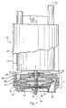
- Figure 1 is a front and partial cut-away view of a fuel pump assembly which is made in accordance with the teachings of the preferred embodiment of the invention;
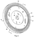
- Figure 2 is an unassembled perspective view of the impeller which is employed within the fuel pump assembly shown in Figure 1;
- Figure 3 is an unassembled perspective view of the pump chamber body member which is employed within the fuel pump assembly shown in Figure 1;
- Figure 4 is an unassembled perspective view of the pump chamber cover which is employed within the fuel pump assembly shown in Figure 1;
- Figure 5 is a cross sectional view of the impeller shown in Figures 1 and 2;
- Figure 6 is a cross sectional view of a pump chamber formed by the selectively and operative engagement of the pump chamber body shown in Figure 3 and the pump chamber cover shown in Figure 4;
- Figure 7 is a perspective unassembled view of a pump chamber body member which is made in accordance with the teachings of a second embodiment of the invention and which is adapted for use with fuel pump which is shown in Figure 1;
- Figure 8 is a perspective unassembled view of a pump chamber cover member which is made in accordance with the teachings of a second embodiment of the invention and which is adapted for use with the fuel pump shown in Figure 1; and
- Figure 9 is a cross sectional view of a fuel pump chamber member which is formed by the selective and operative engagement of the pump chamber body member which is shown in Figure 7 and the pump chamber cover member which is shown in Figure 8.
-
- Referring now to Figures 1 - 6, there is shown a vehicle
fuel pump assembly 10 which is made in accordance with the teachings of the preferred embodiment of the invention. As shown,fuel pump assembly 10 includes amotor 12, adrive shaft 14 which is rotatably and operatively coupled to themotor 12, and achamber assembly 18 which rotatably receives thedriveshaft 14.Motor 12,driveshaft 14, andchamber assembly 18 are collectively contained within a generallycylindrical housing 20. -
Chamber assembly 18 includes achamber cover member 24 having an integrally formed fuel intake passage orport 26, achamber body member 22 having a fuel outlet aperture orport 28 and operatively co-operating withcover member 22 to form achamber cavity 30, and animpeller 16 which is coupled toshaft 14 and which is rotatably disposed withincavity 30.Assembly 10 further includes a pump outlet member orport 32 which is communicatively coupled to aperture orport 28. - As described more fully and completely below, the selective rotation of
impeller 16 causes fuel to be selectively received by theassembly 18 throughport 26. The received fuel is then pumped and/or propelled throughcavity 30 and throughaperture 28, before exitingassembly 10 fromport 32. As should be realised by those of ordinary skill in the art, port oraperture 32 is selectively and communicatively coupled to a conventional vehicle combustion engine (not shown), thereby allowing the fuel to be received and selectively combusted within the engine. - In the preferred embodiment of the invention,
motor 12 comprises a conventional and commercially available electric "DC"-type motor (e.g., a motor which is powered through direct current electricity), and is adapted to selectively and rotatablydrive shaft 14. Particularly,shaft 14 extends frommotor 12 intochamber assembly 18 through anaperture 34 which is formed withinbody member 22. As shown,aperture 34 contains a conventional and commercially available "set" or pair ofbearings 36 which rotatably engageshaft 14 and allowshaft 14 to rotate freely withinaperture 34. Thesebearings 36 causeshaft 14 to rotate about an axis ofrotation 94 which, in one non-limiting embodiment of the invention, is made to maintain a position which substantially overlays and/or corresponds to the longitudinal axis of symmetry ofaperture 34.Shaft 14 further extends throughcavity 30 and into theslot 37 which is formed withincover member 24. Therounded end 38 ofshaft 14 rotatably rests upon a conventional "thrust button" ormember 40 which is secured withinslot 37. - As best shown in Figures 2 and 5,
impeller 16 is generally circular in shape and includes a generally circular and relatively thin inner body orcore portion 42; a generally circular and relatively thick or "landed" outer body orcore portion 44; several relatively thin and curved vanes orblades 46 which are circumferentially disposed upon and which project and/or protrude fromportion 44; several flange portions or "vane groove" 48 which project fromportion 44 and which are each operatively and abuttingly positioned between a unique pair ofblades 46; and anouter ring portion 50 which is connected toblade tips 47, thereby interconnectingblades 46.Portions blades 46, flange portion or "vane groove" 48 andring 50 are, in one non-limiting embodiment of the invention, integrally formed from a durable corrosion-resistant material, such as a phenolic or "PPS" type plastic. In the preferred embodiment,impeller 16 is moulded by use of a conventional thermal moulding process and may include conventional filler materials such as glass, resin and/or graphite. -
Core portion 42 includes a centrally disposedaperture 52 which matingly and frictionally receivesshaft 14. Hence, theshaft 14 is operatively coupled to theimpeller 16, thereby causing theimpeller 16 to rotate and to "freely" slide or travel uponshaft 14 and withinchamber cavity 30 in the directions illustrated byarrows 56, 57 (e.g., along axis 94), shown in Figure 1.Core portions pressure relief apertures 58. Particularly,apertures 58 allow fuel to pass between opposed side surfaces ofimpeller 16, thereby substantially equalising the pressure withincavity 30, substantially reducing the amount of force imparted uponimpeller 16 in the directions illustrated byarrows impeller 16 and thebody 22 and/orcover 24. - To further substantially prevent and/or reduce frictional contact between the
impeller 16 andbody member 22 and between theimpeller 16 and thecover member 24, the "thickness" or thewidth 59 of theblades 46 and thering portion 50 and the "thickness" or thewidth 60 ofportion 42 are each made to be respectively uniform and relatively less than the relatively uniform width or "thickness" 62 ofportion 44. As discussed more fully and completely below, the narrowing and/or thinning ofblades 46,ring 50, andportion 42 ensures thatblades 46,ring 50, andportion 42 will not contact thecover member 24 and/or thebody member 22 during operation, thereby minimising the contact betweenimpeller 16 and the respectiveinterior surfaces pump chamber 30 and allowing thefuel pump assembly 10 to become more efficient. - In one non-limiting embodiment of the present invention, the
thickness 59 is approximately 4.65 millimetres, thethickness 60 is approximately 4.65 millimetres, thethickness 62 is approximately 4.75 millimetres, and theoverall diameter 68 ofimpeller 16 is approximately 54 millimetres. -
Body member 22 andcover member 24 are best illustrated in Figures 3, 4 and 6. As shown,body member 22 andcover member 24 are preferably manufactured from a relatively durable and substantially corrosive-resistant material, such as a plastic material, anodised aluminium, or any other suitable material or composite. Further,body member 22 andcover member 24 each respectively includes an outer ridge orlip portion cavity 30.Body member 22 andcover member 24 each further respectively include an integrally formedsemi-circular groove body member 22 andcover member 24 are operatively interconnected,grooves fuel passage channel 77 which directs the flow of the received fuel within thecavity 30 and, more particularly, provides a path of fuel travel from theinlet 26 to theoutlet 28. - Further,
body member 22 andcover member 24 respectively include taperedsurface portions portions angle 82, which in one non-limiting embodiment is approximately equal to 0.36 degrees. Further, in one non-limiting embodiment,portions identical uniform width Portions chamber 30 in which the relativelythick portion 44 ofimpeller 16 operatively resides, thereby allowingimpeller 16 to move in the direction ofarrows chamber forming surfaces fuel pump assembly 10. In one non-limiting embodiment, distances 88, 90 which respectively correspond to the maximum distance by which eachportion chamber 30 is approximately 0.05 millimetres. - The
overall diameter 92 ofcavity 30 formed by the selective engagement ofbody member 22 andcover member 24 is greater than theoverall impeller diameter 68 to ensure sufficient clearance between blade tips and the chamber forming surface. In one non-limiting embodiment, theoverall diameter 92 ofcavity 30 is approximately 54.2 millimetres. As discussed below,ring portion 50 allowsdiameter 92 to be relatively and considerably greater thanimpeller diameter 68. Particularly,ring portion 50 substantially eliminates/reduces blade tip losses, thereby allowing for a "looser" tolerance betweendiameter 92 anddiameter 68, thereby obviating the need to preciselymachine body 22 and/orcover 24. Furthermore, the "tapering" or "sloping" ofbody member 22 andcover member 24 further reduces the amount of frictional contact betweenimpeller 16 and the interior pumpchamber forming surfaces - In operation, the selective rotation of
shaft 14 bymotor 12causes impeller 16 to rotate withincavity 30 about the axis ofrotation 94 ofshaft 14. The rotation ofimpeller 16 selectively draws fuel throughinlet 26 and pumps and/or propels the received fuel throughcavity 30 andaperture 28, and out ofassembly 10 throughport 32. The rotation ofimpeller 16 causes and/or creates forces which act in the directions ofarrows impeller 16 to slide upward and/or downward uponshaft 14. Unlike prior pump assemblies, these forces do not cause substantial frictional contact between the operatively rotatingimpeller 16 and the pumpchamber forming surfaces - If
impeller 16 is forced "upward" (i.e., in the direction of arrow 56) only thetop surface 64 ofportion 44 will contact theinterior surface 70 ofbody member 22, thereby allowing the relativelythin blades 46 and thering portion 50 to rotate freely belowsurface 70. Should theimpeller 16 be forced "downward" (i.e., in the direction of arrow 57), only thebottom surface 66 ofportion 44 will contact the pump chamber forminginterior surface 72 ofcover member 24, thereby allowing the relativelythin blades 46 and thering portion 50 to rotate freely abovesurface 72. - The "tapering" or "sloping" of
portions 78, 80 (e.g., the selective "widening" of cavity 30) combined with the relatively thininner core portion 42 further minimise the contact betweenimpeller 16 and the respectiveinterior surfaces portion 44 and the portion ofsurfaces respective channels portion 42 and surfaces 70, 72. In this manner, frictional contact between theimpeller 16 andbody 22 and/or covermember 24 is minimised, thereby providing relatively greater impeller speeds, an increased pumping rate, and improved overall pump efficiency. - The efficiency of
pump assembly 10 is further increased due toring 50. Particularly,ring portion 50 allowsdiameter 92 to be significantly greater thanimpeller diameter 68, thereby allowing for a "looser" tolerance. This "looser" tolerance provides a greater distance between the outer circumference ofimpeller 68 and the circumference ofcavity 30, thereby decreasing the amount and likelihood of contact occurring betweenblades 46 andbody 22 and/orcover 24. This "looser" tolerance is achieved without "blade" tip losses, asring 50 encompasses and/or interconnects thetips 47 ofblades 46, thereby preventing or substantially reducing undesirable blade tip fluid displacement during the rotation ofimpeller 16. - It should be understood that the
thin portion 42 ofimpeller 16, thetapered body member 22 andcover member 24, thethin blades 46, and/or thering portion 50 may each be used independently to unilaterally reduce the amount of frictional contact within a fuel pump assembly as previously described. These aspects/features may also be desirably combined with a single fuel pump assembly. - Referring now to Figures 7, 8, and 9, there is respectively shown a
chamber body member 122, achamber cover member 124, and a chamber assembly made in accordance with the teachings of a second embodiment of the present invention. Except as otherwise delineated below,body member 122 andcover member 124 are substantially identical in structure and function tobody member 22 andcover member 24. Particularly,members members fuel pump assembly 10 which has been previously described. Moreover, with the exception ofportions body member 122 andcover member 124 each respectively include substantially identical elements/portions/characteristics asbody member 22 andcover member 24. Elements having a substantially identical structure and function are defined by the same reference numerals asbody member 22 andcover member 24, delineated in Figures 3, 4 and 6, with the exception that elements ofbody member 122 andcover member 124 have their respective reference numerals incremented by 100. - Unlike
portions portions body member 122 andcover member 124 are not "tapered' or "sloped". Rather,portions portions portions Portions channels opposed surfaces -
Portions respective widths respective widths portions widths widths distance portions portions -
Cover member 122 andbody member 124 co-operate withimpeller 16 to substantially ensure that minimal frictional contact results from the movement ofimpeller 16. Particularly, ifimpeller 16 is forced againstbody 122, the only contact which will occur is betweenportion 44 ofimpeller 16 and the relativelythin surface 195 ofportion 179. Likewise, ifimpeller 16 is forced againstcover 124, the only contact which will occur is betweenportion 44 ofimpeller 16 and the relativelythin surface 197 ofportion 181. In this manner, frictional contact between theimpeller 16 andbody 122 and/or cover 124 is substantially reduced, thereby providing relatively greater impeller speeds, an increased pumping rate, and improved efficiency. Moreover, this "stepped" design allowsbody 122 and cover 124 to be more easily moulded and requires less machining than the "tapered" or sloped design ofbody 22 andcover 24.
Claims (10)
- A fuel pump assembly for use with a vehicle of the type having a fuel tank which contains a quantity of fuel and a combustion engine, said fuel pump assembly comprising:a motor (12) having a selectively rotating shaft (14);a chamber (18) which receives said shaft (14) and which is communicatively coupled to said fuel tank and to said combustion engine; andan impeller (16) which is coupled to said shaft (14), which is movably disposed within said chamber (18), and which has a body portion (42,44) and several blade portions (46) which project from said body portion and which are each respectively thinner than said body portion.
- A fuel pump assembly as claimed in Claim 1, wherein said impeller further includes a ring portion which is connected to said several blade portions.
- A fuel pump assembly as claimed in Claim 2, wherein each of said several blade portions has a tip and wherein said ring portion is connected to each of said tips of said blade portions.
- A fuel pump assembly as claimed in Claim 1, wherein said body portion includes a plurality of apertures.
- A fuel pump assembly as claimed in Claim 1, wherein said body portion includes a thin inner portion and a thick outer portion.
- A fuel pump assembly as claimed in Claim 5, wherein said blade portions are integrally formed with and project from said thick outer body portion.
- A fuel pump assembly as claimed in Claim 6, wherein said inner portion of said body is deployed within a first portion of the chamber and wherein said outer portion of said body is deployed within a second portion of said chamber, said first and second portions of said chamber having a respective height and wherein said height of said first portion of said chamber is less than said height of said second portion of said chamber.
- A fuel pump assembly as claimed in Claim 1 further comprising a first member and a second member which co-operatively form said chamber.
- The fuel pump assembly of Claim 8, wherein said first and second members include grooves which co-operatively form a fuel path within said chamber.
- A fuel pump assembly comprising:a housing;a motor disposed within said housing;a shaft which is coupled to and which is rotated by said motor;a pump chamber body member having an aperture through which said shaft extends and further having a first surface in which a first channel is formed, said surface further including a first raised portion and a second portion;a pump chamber cover member having a second surface in which a second channel is formed, and co-operating with said pump chamber body member to form a pump chamber; andan impeller which is coupled to said shaft, disposed with said pump chamber, and being rotated within said chamber by said motor, said impeller having a certain shape which co-operates with said first raised portion to substantially prevent contact between said impeller and said second portion as said impeller rotates within said chamber.
Applications Claiming Priority (2)
| Application Number | Priority Date | Filing Date | Title |
|---|---|---|---|
| US408056 | 1989-09-15 | ||
| US09/408,056 US6270310B1 (en) | 1999-09-29 | 1999-09-29 | Fuel pump assembly |
Publications (1)
| Publication Number | Publication Date |
|---|---|
| EP1088994A1 true EP1088994A1 (en) | 2001-04-04 |
Family
ID=23614682
Family Applications (1)
| Application Number | Title | Priority Date | Filing Date |
|---|---|---|---|
| EP00308226A Withdrawn EP1088994A1 (en) | 1999-09-29 | 2000-09-20 | Fuel pump assembly |
Country Status (3)
| Country | Link |
|---|---|
| US (1) | US6270310B1 (en) |
| EP (1) | EP1088994A1 (en) |
| JP (1) | JP2001115918A (en) |
Cited By (1)
| Publication number | Priority date | Publication date | Assignee | Title |
|---|---|---|---|---|
| DE10341840B4 (en) * | 2003-09-09 | 2006-12-28 | Siemens Ag | Fuel delivery unit |
Families Citing this family (11)
| Publication number | Priority date | Publication date | Assignee | Title |
|---|---|---|---|---|
| JP3800128B2 (en) * | 2001-07-31 | 2006-07-26 | 株式会社デンソー | Impeller and turbine fuel pump |
| US6767181B2 (en) | 2002-10-10 | 2004-07-27 | Visteon Global Technologies, Inc. | Fuel pump |
| US6984099B2 (en) * | 2003-05-06 | 2006-01-10 | Visteon Global Technologies, Inc. | Fuel pump impeller |
| JP2004360678A (en) * | 2003-05-15 | 2004-12-24 | Denso Corp | Fuel pump |
| US20040258545A1 (en) * | 2003-06-23 | 2004-12-23 | Dequan Yu | Fuel pump channel |
| DE10342256A1 (en) * | 2003-09-11 | 2005-04-28 | Siemens Ag | Fuel pump |
| JP2005315158A (en) * | 2004-04-28 | 2005-11-10 | Toshiba Corp | Pumps, cooling devices, and electronics |
| US7267524B2 (en) * | 2004-05-10 | 2007-09-11 | Ford Motor Company | Fuel pump having single sided impeller |
| US7008174B2 (en) * | 2004-05-10 | 2006-03-07 | Automotive Components Holdings, Inc. | Fuel pump having single sided impeller |
| US20170023022A1 (en) * | 2015-07-20 | 2017-01-26 | Delphi Technologies, Inc. | Fluid pump |
| KR102825467B1 (en) * | 2023-05-03 | 2025-07-01 | 주식회사 코아비스 | Washer pump |
Citations (4)
| Publication number | Priority date | Publication date | Assignee | Title |
|---|---|---|---|---|
| US4492515A (en) * | 1982-05-12 | 1985-01-08 | Nippondenso Co., Ltd. | Pump apparatus |
| US4915582A (en) * | 1987-08-12 | 1990-04-10 | Japan Electronic Control Systems Company, Limited | Rotary turbine fluid pump |
| DE8908579U1 (en) * | 1989-07-14 | 1990-11-15 | Robert Bosch Gmbh, 7000 Stuttgart | Unit for pumping fuel |
| US5415521A (en) * | 1992-11-25 | 1995-05-16 | Robert Bosch G.M.B.H. | Aggregate for feeding fuel from supply tank to internal combustion engine of motor vehicle |
Family Cites Families (13)
| Publication number | Priority date | Publication date | Assignee | Title |
|---|---|---|---|---|
| DE3014425C2 (en) * | 1980-04-15 | 1986-06-12 | Friedrich 8541 Röttenbach Schweinfurter | Side channel pump |
| JPS57176691U (en) * | 1981-04-30 | 1982-11-08 | ||
| US4943209A (en) | 1988-07-11 | 1990-07-24 | Heil-Quaker Corporation | Hub for a plastic blower impeller |
| US5009570A (en) | 1989-05-02 | 1991-04-23 | Maytag Corporation | Mounting assembly for the impeller of a fluid pump |
| KR960001631B1 (en) * | 1991-05-14 | 1996-02-03 | 미쓰비시덴키가부시키가이샤 | Circumferential flow type liquid pump |
| US5338165A (en) * | 1991-11-25 | 1994-08-16 | Ford Motor Company | Automotive fuel pump with modular pump housing |
| US5409357A (en) * | 1993-12-06 | 1995-04-25 | Ford Motor Company | Impeller for electric automotive fuel pump |
| DE4438249A1 (en) * | 1994-10-26 | 1996-05-02 | Bosch Gmbh Robert | Fuel supply unit for supplying fuel from tank to IC engine |
| DE4438751A1 (en) | 1994-10-29 | 1996-05-02 | Pierburg Gmbh | Electrically powered air pump |
| US5549446A (en) | 1995-08-30 | 1996-08-27 | Ford Motor Company | In-tank fuel pump for highly viscous fuels |
| FR2738303B1 (en) | 1995-08-30 | 1997-11-28 | Europ Propulsion | TURBINE OF THERMOSTRUCTURAL COMPOSITE MATERIAL, IN PARTICULAR WITH A SMALL DIAMETER, AND METHOD FOR THE PRODUCTION THEREOF |
| DE19549196A1 (en) * | 1995-12-30 | 1997-07-03 | Bosch Gmbh Robert | Fuel supply unit for vehicle internal combustion engine |
| US5899673A (en) * | 1996-10-16 | 1999-05-04 | Capstone Turbine Corporation | Helical flow compressor/turbine permanent magnet motor/generator |
-
1999
- 1999-09-29 US US09/408,056 patent/US6270310B1/en not_active Expired - Fee Related
-
2000
- 2000-09-20 EP EP00308226A patent/EP1088994A1/en not_active Withdrawn
- 2000-09-28 JP JP2000296247A patent/JP2001115918A/en active Pending
Patent Citations (4)
| Publication number | Priority date | Publication date | Assignee | Title |
|---|---|---|---|---|
| US4492515A (en) * | 1982-05-12 | 1985-01-08 | Nippondenso Co., Ltd. | Pump apparatus |
| US4915582A (en) * | 1987-08-12 | 1990-04-10 | Japan Electronic Control Systems Company, Limited | Rotary turbine fluid pump |
| DE8908579U1 (en) * | 1989-07-14 | 1990-11-15 | Robert Bosch Gmbh, 7000 Stuttgart | Unit for pumping fuel |
| US5415521A (en) * | 1992-11-25 | 1995-05-16 | Robert Bosch G.M.B.H. | Aggregate for feeding fuel from supply tank to internal combustion engine of motor vehicle |
Cited By (2)
| Publication number | Priority date | Publication date | Assignee | Title |
|---|---|---|---|---|
| DE10341840B4 (en) * | 2003-09-09 | 2006-12-28 | Siemens Ag | Fuel delivery unit |
| US7708533B2 (en) | 2003-09-09 | 2010-05-04 | Siemens Aktiengesellschaft | Fuel feed unit |
Also Published As
| Publication number | Publication date |
|---|---|
| JP2001115918A (en) | 2001-04-27 |
| US6270310B1 (en) | 2001-08-07 |
Similar Documents
| Publication | Publication Date | Title |
|---|---|---|
| US6270310B1 (en) | Fuel pump assembly | |
| US7037066B2 (en) | Turbine fuel pump impeller | |
| EP0955468B1 (en) | Centrifugal flow fan and fan/orifice assembly | |
| JP4495291B2 (en) | Turbine fuel pump | |
| EP0646726B1 (en) | A fuel pump | |
| US5409357A (en) | Impeller for electric automotive fuel pump | |
| US6932562B2 (en) | Single stage, dual channel turbine fuel pump | |
| US6425733B1 (en) | Turbine fuel pump | |
| US5401147A (en) | Automotive fuel pump with convergent flow channel | |
| KR102083168B1 (en) | Impeller having primary blades and secondary blades | |
| US6527506B2 (en) | Pump section for fuel pump | |
| US6974302B2 (en) | Turbine fuel pump | |
| WO2018153350A1 (en) | Impeller and electric pump | |
| JP2001153081A (en) | Regenerating fuel pump with force balanced impeller | |
| EP1028256B1 (en) | Impeller for electric automotive fuel pump | |
| CN101187369A (en) | Vane pump | |
| US7318703B2 (en) | Impeller for a pump | |
| EP1138953B1 (en) | Impeller for circumferential current pump | |
| US5375975A (en) | Fuel pump pre-swirl inlet channel | |
| JP4235665B2 (en) | FUEL PUMP AND FUEL SUPPLY DEVICE USED FOR AUTOMOBILE INTERNAL COMBUSTION ENGINE | |
| CN1071421C (en) | liquid pump | |
| EP3540240B1 (en) | Centrifugal compressor open impeller | |
| US20060008344A1 (en) | Fuel pump | |
| US20040247468A1 (en) | Fuel pump | |
| US20040013513A1 (en) | Impeller for fuel pump |
Legal Events
| Date | Code | Title | Description |
|---|---|---|---|
| PUAI | Public reference made under article 153(3) epc to a published international application that has entered the european phase |
Free format text: ORIGINAL CODE: 0009012 |
|
| AK | Designated contracting states |
Kind code of ref document: A1 Designated state(s): DE FR GB |
|
| AX | Request for extension of the european patent |
Free format text: AL;LT;LV;MK;RO;SI |
|
| 17P | Request for examination filed |
Effective date: 20010915 |
|
| AKX | Designation fees paid |
Free format text: DE FR GB |
|
| 17Q | First examination report despatched |
Effective date: 20040303 |
|
| STAA | Information on the status of an ep patent application or granted ep patent |
Free format text: STATUS: THE APPLICATION IS DEEMED TO BE WITHDRAWN |
|
| 18D | Application deemed to be withdrawn |
Effective date: 20040914 |