EP1088689A2 - Compound heat exchanger having two cores - Google Patents
Compound heat exchanger having two cores Download PDFInfo
- Publication number
- EP1088689A2 EP1088689A2 EP00118294A EP00118294A EP1088689A2 EP 1088689 A2 EP1088689 A2 EP 1088689A2 EP 00118294 A EP00118294 A EP 00118294A EP 00118294 A EP00118294 A EP 00118294A EP 1088689 A2 EP1088689 A2 EP 1088689A2
- Authority
- EP
- European Patent Office
- Prior art keywords
- side plate
- heat exchanger
- tank
- caps
- cap
- Prior art date
- Legal status (The legal status is an assumption and is not a legal conclusion. Google has not performed a legal analysis and makes no representation as to the accuracy of the status listed.)
- Granted
Links
Images





Classifications
-
- F—MECHANICAL ENGINEERING; LIGHTING; HEATING; WEAPONS; BLASTING
- F28—HEAT EXCHANGE IN GENERAL
- F28F—DETAILS OF HEAT-EXCHANGE AND HEAT-TRANSFER APPARATUS, OF GENERAL APPLICATION
- F28F9/00—Casings; Header boxes; Auxiliary supports for elements; Auxiliary members within casings
- F28F9/001—Casings in the form of plate-like arrangements; Frames enclosing a heat exchange core
- F28F9/002—Casings in the form of plate-like arrangements; Frames enclosing a heat exchange core with fastening means for other structures
-
- B—PERFORMING OPERATIONS; TRANSPORTING
- B60—VEHICLES IN GENERAL
- B60H—ARRANGEMENTS OF HEATING, COOLING, VENTILATING OR OTHER AIR-TREATING DEVICES SPECIALLY ADAPTED FOR PASSENGER OR GOODS SPACES OF VEHICLES
- B60H1/00—Heating, cooling or ventilating devices
- B60H1/00321—Heat exchangers for air-conditioning devices
- B60H1/00328—Heat exchangers for air-conditioning devices of the liquid-air type
-
- B—PERFORMING OPERATIONS; TRANSPORTING
- B60—VEHICLES IN GENERAL
- B60H—ARRANGEMENTS OF HEATING, COOLING, VENTILATING OR OTHER AIR-TREATING DEVICES SPECIALLY ADAPTED FOR PASSENGER OR GOODS SPACES OF VEHICLES
- B60H1/00—Heating, cooling or ventilating devices
- B60H1/32—Cooling devices
- B60H1/3204—Cooling devices using compression
- B60H1/3227—Cooling devices using compression characterised by the arrangement or the type of heat exchanger, e.g. condenser, evaporator
-
- F—MECHANICAL ENGINEERING; LIGHTING; HEATING; WEAPONS; BLASTING
- F28—HEAT EXCHANGE IN GENERAL
- F28D—HEAT-EXCHANGE APPARATUS, NOT PROVIDED FOR IN ANOTHER SUBCLASS, IN WHICH THE HEAT-EXCHANGE MEDIA DO NOT COME INTO DIRECT CONTACT
- F28D1/00—Heat-exchange apparatus having stationary conduit assemblies for one heat-exchange medium only, the media being in contact with different sides of the conduit wall, in which the other heat-exchange medium is a large body of fluid, e.g. domestic or motor car radiators
- F28D1/02—Heat-exchange apparatus having stationary conduit assemblies for one heat-exchange medium only, the media being in contact with different sides of the conduit wall, in which the other heat-exchange medium is a large body of fluid, e.g. domestic or motor car radiators with heat-exchange conduits immersed in the body of fluid
- F28D1/04—Heat-exchange apparatus having stationary conduit assemblies for one heat-exchange medium only, the media being in contact with different sides of the conduit wall, in which the other heat-exchange medium is a large body of fluid, e.g. domestic or motor car radiators with heat-exchange conduits immersed in the body of fluid with tubular conduits
- F28D1/0408—Multi-circuit heat exchangers, e.g. integrating different heat exchange sections in the same unit or heat exchangers for more than two fluids
- F28D1/0426—Multi-circuit heat exchangers, e.g. integrating different heat exchange sections in the same unit or heat exchangers for more than two fluids with units having particular arrangement relative to the large body of fluid, e.g. with interleaved units or with adjacent heat exchange units in common air flow or with units extending at an angle to each other or with units arranged around a central element
- F28D1/0435—Combination of units extending one behind the other
-
- F—MECHANICAL ENGINEERING; LIGHTING; HEATING; WEAPONS; BLASTING
- F28—HEAT EXCHANGE IN GENERAL
- F28D—HEAT-EXCHANGE APPARATUS, NOT PROVIDED FOR IN ANOTHER SUBCLASS, IN WHICH THE HEAT-EXCHANGE MEDIA DO NOT COME INTO DIRECT CONTACT
- F28D21/00—Heat-exchange apparatus not covered by any of the groups F28D1/00 - F28D20/00
- F28D2021/0019—Other heat exchangers for particular applications; Heat exchange systems not otherwise provided for
- F28D2021/008—Other heat exchangers for particular applications; Heat exchange systems not otherwise provided for for vehicles
- F28D2021/0084—Condensers
-
- F—MECHANICAL ENGINEERING; LIGHTING; HEATING; WEAPONS; BLASTING
- F28—HEAT EXCHANGE IN GENERAL
- F28D—HEAT-EXCHANGE APPARATUS, NOT PROVIDED FOR IN ANOTHER SUBCLASS, IN WHICH THE HEAT-EXCHANGE MEDIA DO NOT COME INTO DIRECT CONTACT
- F28D21/00—Heat-exchange apparatus not covered by any of the groups F28D1/00 - F28D20/00
- F28D2021/0019—Other heat exchangers for particular applications; Heat exchange systems not otherwise provided for
- F28D2021/008—Other heat exchangers for particular applications; Heat exchange systems not otherwise provided for for vehicles
- F28D2021/0091—Radiators
- F28D2021/0094—Radiators for recooling the engine coolant
-
- F—MECHANICAL ENGINEERING; LIGHTING; HEATING; WEAPONS; BLASTING
- F28—HEAT EXCHANGE IN GENERAL
- F28F—DETAILS OF HEAT-EXCHANGE AND HEAT-TRANSFER APPARATUS, OF GENERAL APPLICATION
- F28F9/00—Casings; Header boxes; Auxiliary supports for elements; Auxiliary members within casings
- F28F9/001—Casings in the form of plate-like arrangements; Frames enclosing a heat exchange core
- F28F2009/004—Common frame elements for multiple cores
-
- F—MECHANICAL ENGINEERING; LIGHTING; HEATING; WEAPONS; BLASTING
- F28—HEAT EXCHANGE IN GENERAL
- F28F—DETAILS OF HEAT-EXCHANGE AND HEAT-TRANSFER APPARATUS, OF GENERAL APPLICATION
- F28F2215/00—Fins
- F28F2215/02—Arrangements of fins common to different heat exchange sections, the fins being in contact with different heat exchange media
-
- F—MECHANICAL ENGINEERING; LIGHTING; HEATING; WEAPONS; BLASTING
- F28—HEAT EXCHANGE IN GENERAL
- F28F—DETAILS OF HEAT-EXCHANGE AND HEAT-TRANSFER APPARATUS, OF GENERAL APPLICATION
- F28F2275/00—Fastening; Joining
- F28F2275/04—Fastening; Joining by brazing
Definitions
- the present invention relates to a compound heat exchanger having plural heat exchanger cores, and more particularly to a compound heat exchanger having a condenser core for cooling refrigerant in an air-conditioning system and a radiator core for cooling coolant of an internal combustion engine.
- the compound heat exchanger is suitably used in an automobile vehicle.
- JP-U-4-115281 An example of a compound heat exchanger having a condenser core and a radiator core is disclosed in JP-U-4-115281.
- the condenser core and the radiator core are connected into a single unit by an integrally formed member having a condenser header tank cap and a radiator header tank cap.
- the condenser header tank cap closes an open end of the condenser header tank connected to the condenser core, while the radiator header tank cap closes an open end of the radiator header tank connected to the radiator core.
- the present invention has been made in view of the above-mentioned problem, and an object of the present invention is to provide an improved compound heat exchanger in which the heat transfer between two header tanks is suppressed and a high heat radiation capacity is realized.
- the compound heat exchanger includes a first heat exchanger such as a condenser for cooling refrigerant circulating in an air-conditioner and a second heat exchanger such as a radiator for cooling coolant in an internal combustion engine.
- the first and the second heat exchangers are overlapped on each other in an airflow direction of cooling air.
- Both heat exchangers have a similar structure, that is, each heat exchanger is composed of a core having plural tubes and fins and a pair of header tanks connected to both ends of the tubes.
- Both cores are connected to each other by a side plate disposed on the top of both cores, so that at least a top fin of one of the cores, preferably both top fins, contacts the side plate in heat conductive relation.
- a pair of fins for both cores is formed as a unitary part, and each header tank is formed by connecting two separate elongate cup-shaped or L-shaped parts.
- both header tanks are closed with respective tank caps that are connected to the side plate.
- the compound heat exchanger is connected into single unit by a brazing process. Since both tank caps are separate from each other, though they are connected to the common side plate, heat in one header tank is not directly transferred to the other header tank. For example, most heat in the radiator header tank is transferred to the side plate via its tank cap and is radiated front the side plate and the fin contacting the side plate. Accordingly, the radiation capacity is not much decreased by combining two heat exchangers.
- positioning walls and side walls are formed on the side plate to fix the tank caps at correct positions and thereby to prevent the header tanks from being positioned with slanted angles relative to the cores.
- the tank caps are inserted and held between the positioning and side walls of the side plate when assembled, and then the tank caps and the side plate are firmly connected by brazing.
- Both tank caps may be made as a single part having cap portions and connecting portions, as long as two cap portions are separated from each other with a certain space therebetween.
- both tank caps may be formed integrally with the side plate, with cap portions being positioned separately form each other.
- one of the tank caps may be formed integrally with the side plate, while the other one is separately made and connected to the side plate by brazing.
- Both tank caps may be integrated with a mounting bracket via connecting portions with cap portions being positioned separately from each other.
- the heat in one header tank is not directly transferred to the other header tank, and therefore a high radiation capacity in the combined heat exchanger is realized.
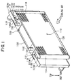
- FIGS. 1 - 7 An entire structure of a compound heat exchanger 100 is shown in FIGS. 1 and 2.
- FIG. 1 shows a perspective view of the compound heat exchanger 100, viewed from the front side from which cooling air is supplied.
- FIG. 2 shows the compound heat exchanger, viewed from the rear side.
- a radiator for cooling coolant in an internal combustion engine and a condenser for cooling refrigerant in an air-conditioning system of an automobile vehicle are combined into a single unit as a compound heat exchanger 100.
- the condenser is overlapped on the front surface of the radiator, so that cooling air is supplied to the condenser first and then flows through the radiator.
- the condenser is composed of: a condenser core 110 having condenser tubes 111 and condenser fins 112; and a pair of condenser header tanks 113, 114 connected to both sides of the core 110, as shown in FIG. 1.
- a condenser core 110 plural aluminum tubes 111 are horizontally disposed between two header tanks 113, 114, and wave-shaped aluminum fins 112 are inserted and connected between tubes 111.
- the refrigerant in the right side header tank 113 is distributed to the tubes 111 and flows therethrough toward the left side header tank 114.
- the left side header tank 114 collects the refrigerant flowing through the tubes 111.
- the fins 112 expedite heat exchange between the refrigerant and the cooling air.
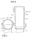
- a condenser header tank body 113b is formed by connecting a cup-shaped elongate condenser core plate 113a and a similarly shaped condenser core plate cover 113c.
- the condenser header tank body 113b is vertically disposed, and an end of the horizontally disposed condenser tubes 111 is open inside the header tank body 113b, so that the refrigerant communicates between the header tank body 113b and the tubes 111. Both longitudinal ends of the header tank body 113b are closed with the header tank caps 113d.
- the radiator is composed of: a radiator core 120 having radiator tubes 121 and radiator fins 122; and a pair of radiator header tanks 123, 124 connected to both sides of the core 120.
- a radiator core 120 plural aluminum tubes 121 are horizontally disposed between two header tanks 123, 124, and wave-shaped aluminum fins 122 are inserted and connected between tubes 121.
- the coolant, such as water, in the left side header tank 123 is distributed to the tubes 121 and flows therethrough toward the right side header tank 124.
- the right side header tank 124 collects the coolant flowing through the tubes 121.
- the fins 122 expedite heat exchange between the coolant and the cooling air.
- a radiator header tank body 123c is formed by connecting an L-shaped tank plate 123a and another L-shaped tank plate 123b.
- the radiator header tank body 123c is vertically disposed, and an end of the horizontally disposed radiator tubes 121 is open inside the header tank body 123c, so that the coolant communicates between the header tank body 123c and the tubes 121. Both longitudinal ends of the header tank body 123c are closed with the header tank caps 123d.
- the condenser core 110 and the radiator core 120 are formed in a unitary body. That is, the condenser fins 112 and the radiator fins 122 are integrally formed, and a side plate 130 supports both the condenser core 110 and the radiator core 120, the integrally formed fins 112, 122 being in contact with the side plate 130.
- the side plate 130 is angled upward to form side walls 130b at its both sides.
- the condenser tube 111 is formed by extrusion or drawing into a flat-oval shape having plural through-passages therein.
- the radiator tube 121 is also formed into a flat-oval shape having a single through-passage therein.
- a short diameter h2 of the radiator tube 121 is larger than a short diameter h1 of the condenser tube 111, and a long diameter W2 of the radiator tube 121 is substantially equal to a long diameter W1 of the condenser tube 111.
- Both tubes 111, 121 are positioned in the cores 110, 120, so that the long diameter of both tubes 111, 121 lies in parallel to the flow direction of the cooling air.
- All the components forming the condenser and the radiator i.e., the tubes 111, 121, the fins 112, 122, the header tanks 113, 114, 123, 124, the tank caps 113d, 123d, and the side plate 130, are brazed in a furnace to form a single unit after they are all assembled.
- the brazing is performed under a known NOCOLOK brazing method. That is, after a flux for removing an oxidized film from brazing-material-clad-aluminum is coated, the components are brazed in a furnace under an inert gas ambient.
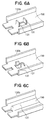
- both tank caps 113d and 123d respectively include connecting portions 113e and 123e that extend toward the side plate 130. Both tank caps 113d, 123d are connected to the side plate 130 by brazing, as shown in FIG. 5. Positioning walls 131 are formed on the side plate 130, as shown in FIG. 6A. Both connecting portions 113e, 123e are inserted between the side walls 130b and the positioning walls 131, as shown in FIG. 7, and thereby the tank caps 113d, 123d are correctly positioned. The tank caps 113d and 123d close the upper openings of the condenser header tank body 113b and the radiator header tank body 123c, respectively.
- the positioning walls 131 shown in FIG. 6A may be variously modified, for example, to the forms shown in FIGS. 6B and 6C.
- the embodiment described above has the following advantages. Since the tank caps 113d and 123d are separately made and then connected to the side pale 130 via the connecting portions 113e and 123e, the heat in the radiator header tanks 123, 124 is not directly transferred to the condenser header tanks 113, 114. Further, the side plate 130 contacts both the condenser fins 112 and the radiator fins 122. Therefore, most heat in the radiator header tanks 123, 124 transferred to the side plate 130 via the radiator header tank caps 123d is radiated from both fins 122, 112.
- the radiation capacity of the condenser core 110 is not much decreased by the heat transfer from the radiator header tanks 123, 124 to the condenser header tanks 113, 114. In other words, the radiation capacity decrease in the condenser core 110 due to the heat transfer is prevented.
- both header tank caps 113d and 123d are held by the positioning walls 131 in the side plate 130, the caps do not move relative to the side plate during the brazing process, keeping their correct positions. Further, since both tank caps 113d, 123d are inserted into both header tank bodies 113b, 123c, their positions are correctly kept relative to the side plate 130 without being connected to the side plate 130 with a slated angle during the brazing process. Though each of the header tanks, 113, 114, 123 and 124, is formed by connecting two parts separated along the longitudinal direction, as shown in FIG. 3, it is correctly positioned due to the structure of the header tank caps and the side plate. Accordingly, all the components are firmly and correctly connected in the brazing process, forming the compound heat exchanger 100 having a high mechanical strength.
- FIGS. 8A and 8B A second embodiment of the present invention will be described with reference to FIGS. 8A and 8B.
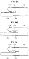
- the condenser header tank cap 113d and the radiator header tank cap 123d are formed as a single unit as shown in FIG. 8A. Both cap portions are separated from each other, but the connecting portions 113e and 123e are connected together and inserted between the side walls 130b of the side plate 130. The positioning walls 131 are eliminated because those are not necessary in this structure. All the components including the header tanks and the caps can be firmly and correctly connected, forming the compound heat exchanger with a high strength.
- FIG. 9 A third embodiment is shown in FIG. 9, in which both header tank caps 113d and 123d are separately formed, and the connecting portions 113e and 123e are inserted between side walls 130b of the side plate 130. Since both connecting portions 113e, 123e are inserted side by side contacting each other, no positioning wall 131 is required.
- FIG. 10 A fourth embodiment is shown in FIG. 10, in which both header tank caps 113d, 123d are formed integrally with the side plate 130. Both cap portions are separated from each other, but they are connected to the side plate via respective connecting portions 113e, 123e.
- FIG. 11 A fifth embodiment is shown in FIG. 11, in which the connecting portions 113e, 123e of both header tank caps 113d, 123d are connected to each other, and a bracket having a pin 150 for mounting both cores 110, 120 on the vehicle is also connected to the connecting portions 113e, 123e. All those portions are formed as a single unit, though the cap portions of both caps 113d, 123d are formed with a separating space therebetween.
- FIG. 12 A sixth embodiment is shown in FIG. 12.
- the side plate 130 and the condenser header tank cap 113d are formed as an integral part, and the radiator header tank cap 123d is formed separately.
- the radiator header tank cap 123d is connected to the integral part by brazing.
- the positioning walls 131 formed on the side plate 130 correctly position the radiator header tank cap 123d on the side plate 130.
- Direct heat transfer form the radiator header tanks 123, 124 to the condenser header tanks 113, 114 are prevented in this structure, too. All the header tanks and the caps can be connected together at their correct positions by brazing.
- the radiator header tank cap 123d and the side plate 130 may be made as an integral part, and a separately made condenser header tank cap 113d may be connected to the integral part by brazing.
- a common side plate 130 supports both the condenser core 110 and the radiator core 120 in all the embodiments described above, it is also possible to make two separate side plates for respective cores 110, 120 and to connect those two side plates together by brazing. Also, two separate side plates may be connected to the bracket for mounting both cores 110, 120 on the vehicle.
Landscapes
- Engineering & Computer Science (AREA)
- Physics & Mathematics (AREA)
- Thermal Sciences (AREA)
- Mechanical Engineering (AREA)
- General Engineering & Computer Science (AREA)
- Details Of Heat-Exchange And Heat-Transfer (AREA)
- Heat-Exchange Devices With Radiators And Conduit Assemblies (AREA)
- Air-Conditioning For Vehicles (AREA)
Abstract
Description
- The present invention relates to a compound heat exchanger having plural heat exchanger cores, and more particularly to a compound heat exchanger having a condenser core for cooling refrigerant in an air-conditioning system and a radiator core for cooling coolant of an internal combustion engine. The compound heat exchanger is suitably used in an automobile vehicle.
- An example of a compound heat exchanger having a condenser core and a radiator core is disclosed in JP-U-4-115281. In this compound heat exchanger, the condenser core and the radiator core are connected into a single unit by an integrally formed member having a condenser header tank cap and a radiator header tank cap. The condenser header tank cap closes an open end of the condenser header tank connected to the condenser core, while the radiator header tank cap closes an open end of the radiator header tank connected to the radiator core.
- In the conventional compound heat exchanger disclosed in the above publication, heat in the radiator header tank is transferred to the condenser header tank through the integrally formed member because both header tanks are connected by the integrally formed member. Therefore, the refrigerant in the condenser header tank is heated by the heat transferred from the radiator header tank, and thereby a heat radiation capacity of the condenser core decreases.
- The present invention has been made in view of the above-mentioned problem, and an object of the present invention is to provide an improved compound heat exchanger in which the heat transfer between two header tanks is suppressed and a high heat radiation capacity is realized.
- The compound heat exchanger includes a first heat exchanger such as a condenser for cooling refrigerant circulating in an air-conditioner and a second heat exchanger such as a radiator for cooling coolant in an internal combustion engine. The first and the second heat exchangers are overlapped on each other in an airflow direction of cooling air. Both heat exchangers have a similar structure, that is, each heat exchanger is composed of a core having plural tubes and fins and a pair of header tanks connected to both ends of the tubes. Both cores are connected to each other by a side plate disposed on the top of both cores, so that at least a top fin of one of the cores, preferably both top fins, contacts the side plate in heat conductive relation. Preferably, a pair of fins for both cores is formed as a unitary part, and each header tank is formed by connecting two separate elongate cup-shaped or L-shaped parts.
- Upper openings of both header tanks are closed with respective tank caps that are connected to the side plate. After all the components, header tanks, cores, tank caps and the side plate are assembled together, the compound heat exchanger is connected into single unit by a brazing process. Since both tank caps are separate from each other, though they are connected to the common side plate, heat in one header tank is not directly transferred to the other header tank. For example, most heat in the radiator header tank is transferred to the side plate via its tank cap and is radiated front the side plate and the fin contacting the side plate. Accordingly, the radiation capacity is not much decreased by combining two heat exchangers.
- Preferably, positioning walls and side walls are formed on the side plate to fix the tank caps at correct positions and thereby to prevent the header tanks from being positioned with slanted angles relative to the cores. The tank caps are inserted and held between the positioning and side walls of the side plate when assembled, and then the tank caps and the side plate are firmly connected by brazing.
- Both tank caps may be made as a single part having cap portions and connecting portions, as long as two cap portions are separated from each other with a certain space therebetween. Alternatively, both tank caps may be formed integrally with the side plate, with cap portions being positioned separately form each other. Further, one of the tank caps may be formed integrally with the side plate, while the other one is separately made and connected to the side plate by brazing. Both tank caps may be integrated with a mounting bracket via connecting portions with cap portions being positioned separately from each other.
- According to the present invention, the heat in one header tank is not directly transferred to the other header tank, and therefore a high radiation capacity in the combined heat exchanger is realized.
- Other objects and features of the present invention will become more readily apparent from a better understanding of the preferred embodiments described below with reference to the following drawings.
-
- FIG. 1 is a perspective view showing a compound heat exchanger as a first embodiment of the present invention, viewed from a front side from which cooling air is supplied;
- FIG. 2 is perspective view showing the same compound heat exchanger as shown in FIG. 1, viewed from a rear side thereof;
- FIG. 3 is a partial cross-sectional view of the compound heat exchanger, showing a condenser header tank and a radiator header tank;
- FIG. 4 is a partial cross-sectional view of the compound heat exchanger, showing laminated tubes and fins;
- FIG. 5 is a partial top view of the compound heat exchanger, showing a portion including header tank caps and a side plate;
- FIG. 6A is a perspective view showing a side plate having walls for positioning the header tank caps;
- FIGS. 6B and 6C are perspective views respectively showing modified forms of the positioning walls shown in FIG. 6A;
- FIG. 7 is a perspective view showing respective directions for assembling header tank bodies, header tank caps and a side plate;
- FIG. 8A is a partial top view of the compound heat exchanger as a second embodiment of the present invention, showing a portion including header tank caps and a side plate;
- FIG. 8B is a partial top view showing a modified form of the portion shown in FIG. 8A;
- FIG. 9 is a partial top view of the compound heat exchanger as a third embodiment of the present invention, showing a portion including header tank caps and a side plate;
- FIG. 10 is a perspective view showing header tank caps integrally formed with a side plate as a fourth embodiment of the present invention;
- FIG. 11 is a perspective view showing header tank caps formed together with a mounting bracket, as a fifth embodiment of the present invention; and
- FIG. 12 is a partial top view of the compound heat exchanger as a sixth embodiment of the present invention, showing a portion including header tank caps and a side plate.
-
- A first embodiment of the present invention will be described with reference to FIGS. 1 - 7. An entire structure of a
compound heat exchanger 100 is shown in FIGS. 1 and 2. FIG. 1 shows a perspective view of thecompound heat exchanger 100, viewed from the front side from which cooling air is supplied. FIG. 2 shows the compound heat exchanger, viewed from the rear side. A radiator for cooling coolant in an internal combustion engine and a condenser for cooling refrigerant in an air-conditioning system of an automobile vehicle are combined into a single unit as acompound heat exchanger 100. The condenser is overlapped on the front surface of the radiator, so that cooling air is supplied to the condenser first and then flows through the radiator. - The condenser is composed of: a
condenser core 110 havingcondenser tubes 111 andcondenser fins 112; and a pair ofcondenser header tanks core 110, as shown in FIG. 1. In thecondenser core 110,plural aluminum tubes 111 are horizontally disposed between twoheader tanks shaped aluminum fins 112 are inserted and connected betweentubes 111. The refrigerant in the rightside header tank 113 is distributed to thetubes 111 and flows therethrough toward the leftside header tank 114. The leftside header tank 114 collects the refrigerant flowing through thetubes 111. Thefins 112 expedite heat exchange between the refrigerant and the cooling air. - As shown in FIG. 3, a condenser
header tank body 113b is formed by connecting a cup-shaped elongatecondenser core plate 113a and a similarly shaped condensercore plate cover 113c. The condenserheader tank body 113b is vertically disposed, and an end of the horizontally disposedcondenser tubes 111 is open inside theheader tank body 113b, so that the refrigerant communicates between theheader tank body 113b and thetubes 111. Both longitudinal ends of theheader tank body 113b are closed with theheader tank caps 113d. - As shown in FIG. 2 the radiator is composed of: a
radiator core 120 havingradiator tubes 121 andradiator fins 122; and a pair ofradiator header tanks core 120. In theradiator core 120,plural aluminum tubes 121 are horizontally disposed between twoheader tanks aluminum fins 122 are inserted and connected betweentubes 121. The coolant, such as water, in the leftside header tank 123 is distributed to thetubes 121 and flows therethrough toward the rightside header tank 124. The rightside header tank 124 collects the coolant flowing through thetubes 121. Thefins 122 expedite heat exchange between the coolant and the cooling air. - As shown in FIG. 3, a radiator
header tank body 123c is formed by connecting an L-shapedtank plate 123a and another L-shapedtank plate 123b. The radiatorheader tank body 123c is vertically disposed, and an end of the horizontally disposedradiator tubes 121 is open inside theheader tank body 123c, so that the coolant communicates between theheader tank body 123c and thetubes 121. Both longitudinal ends of theheader tank body 123c are closed with theheader tank caps 123d. - As shown in FIG. 4, the
condenser core 110 and theradiator core 120 are formed in a unitary body. That is, thecondenser fins 112 and theradiator fins 122 are integrally formed, and aside plate 130 supports both thecondenser core 110 and theradiator core 120, the integrally formedfins side plate 130. Theside plate 130 is angled upward to formside walls 130b at its both sides. Thecondenser tube 111 is formed by extrusion or drawing into a flat-oval shape having plural through-passages therein. Theradiator tube 121 is also formed into a flat-oval shape having a single through-passage therein. A short diameter h2 of theradiator tube 121 is larger than a short diameter h1 of thecondenser tube 111, and a long diameter W2 of theradiator tube 121 is substantially equal to a long diameter W1 of thecondenser tube 111. Bothtubes cores tubes - All the components forming the condenser and the radiator, i.e., the
tubes fins header tanks tank caps side plate 130, are brazed in a furnace to form a single unit after they are all assembled. The brazing is performed under a known NOCOLOK brazing method. That is, after a flux for removing an oxidized film from brazing-material-clad-aluminum is coated, the components are brazed in a furnace under an inert gas ambient. - As shown in FIGS. 1, 2 and 5, both
tank caps portions side plate 130. Bothtank caps side plate 130 by brazing, as shown in FIG. 5. Positioningwalls 131 are formed on theside plate 130, as shown in FIG. 6A. Both connectingportions side walls 130b and thepositioning walls 131, as shown in FIG. 7, and thereby thetank caps header tank body 113b and the radiatorheader tank body 123c, respectively. Thepositioning walls 131 shown in FIG. 6A may be variously modified, for example, to the forms shown in FIGS. 6B and 6C. - The embodiment described above has the following advantages. Since the tank caps 113d and 123d are separately made and then connected to the side pale 130 via the connecting
portions radiator header tanks condenser header tanks side plate 130 contacts both thecondenser fins 112 and theradiator fins 122. Therefore, most heat in theradiator header tanks side plate 130 via the radiatorheader tank caps 123d is radiated from bothfins radiator fins 122.) Accordingly, the radiation capacity of thecondenser core 110 is not much decreased by the heat transfer from theradiator header tanks condenser header tanks condenser core 110 due to the heat transfer is prevented. - Since both header tank caps 113d and 123d are held by the
positioning walls 131 in theside plate 130, the caps do not move relative to the side plate during the brazing process, keeping their correct positions. Further, since bothtank caps header tank bodies side plate 130 without being connected to theside plate 130 with a slated angle during the brazing process. Though each of the header tanks, 113, 114, 123 and 124, is formed by connecting two parts separated along the longitudinal direction, as shown in FIG. 3, it is correctly positioned due to the structure of the header tank caps and the side plate. Accordingly, all the components are firmly and correctly connected in the brazing process, forming thecompound heat exchanger 100 having a high mechanical strength. - A second embodiment of the present invention will be described with reference to FIGS. 8A and 8B. In this embodiment, the condenser
header tank cap 113d and the radiatorheader tank cap 123d are formed as a single unit as shown in FIG. 8A. Both cap portions are separated from each other, but the connectingportions side walls 130b of theside plate 130. Thepositioning walls 131 are eliminated because those are not necessary in this structure. All the components including the header tanks and the caps can be firmly and correctly connected, forming the compound heat exchanger with a high strength. Since the cap portions of bothcaps radiator header tanks condenser header tanks - A third embodiment is shown in FIG. 9, in which both header tank caps 113d and 123d are separately formed, and the connecting
portions side walls 130b of theside plate 130. Since both connectingportions positioning wall 131 is required. - A fourth embodiment is shown in FIG. 10, in which both
header tank caps side plate 130. Both cap portions are separated from each other, but they are connected to the side plate via respective connectingportions - A fifth embodiment is shown in FIG. 11, in which the connecting
portions header tank caps pin 150 for mounting bothcores portions caps - A sixth embodiment is shown in FIG. 12. The
side plate 130 and the condenserheader tank cap 113d are formed as an integral part, and the radiatorheader tank cap 123d is formed separately. The radiatorheader tank cap 123d is connected to the integral part by brazing. Thepositioning walls 131 formed on theside plate 130 correctly position the radiatorheader tank cap 123d on theside plate 130. Direct heat transfer form theradiator header tanks condenser header tanks header tank cap 113d and theside plate 130 as an integral part, the radiatorheader tank cap 123d and theside plate 130 may be made as an integral part, and a separately made condenserheader tank cap 113d may be connected to the integral part by brazing. - Though a
common side plate 130 supports both thecondenser core 110 and theradiator core 120 in all the embodiments described above, it is also possible to make two separate side plates forrespective cores cores - While the present invention has been shown and described with reference to the foregoing preferred embodiments, it will be apparent to those skilled in the art that changes in form and detail may be made therein without departing from the scope of the invention as defined in the appended claims.
Claims (12)
- A compound heat exchanger (100) comprising:a first heat exchanger comprising a plurality of first tubes (111), a pair of first header tanks (113, 114) connected to both ends of the first tubes, and a plurality of first fins (112) connected between the first tubes, heat being exchanged between a first fluid contained in the first heat exchanger and cooling air blown to the first heat exchanger;a second heat exchanger comprising a plurality of second tubes (121), a pair of second header tanks (123, 124) connected to both ends of the second tubes, and a plurality of second fins (122) connected between the second tubes, heat being exchanged between a second fluid contained in the second heat exchanger and cooling air blown to the second heat exchanger; anda side plate (130) connecting the first and the second heat exchangers so that both heat exchangers are overlapped on each other in a flow direction of the cooling air, wherein:the first header tank (113, 114) includes a first tank cap (113d) closing a longitudinal end of the first header tank;the second header tank (123, 124) includes a second tank cap (123d) closing a longitudinal end of the second header tank;at least one of the first and the second fins is connected to the side plate in heat conductive relation; andat least one of the first and second tank caps is connected to the side plate in heat conductive relation.
- The compound heat exchanger as in claim 1, wherein:the first heat exchanger is a condenser for cooling refrigerant circulating in an air conditioning system; andthe second heat exchanger is a radiator for cooling coolant for an internal combustion engine.
- The compound heat exchanger as in claim 1, wherein:each of the first and second header tanks (113, 114; 123, 124) is formed by connecting two elongate components (113a, 113c; 123a, 123b).
- The compound heat exchanger as in claim 1, wherein:the first fins (112) and the second fins (122) form a plurality of pairs, each pair being integrally formed as a unitary part.
- The compound heat exchanger as in claim 1, wherein:the side plate (130) includes positioning walls (131) for correctly positioning the first and the second tank caps (113d, 123d) on the side plate.
- The compound heat exchanger as in claim 1, wherein:each of the first and the second tank caps (113d, 123d) includes a connecting portion (113e, 123e) extending toward the side plate; andthe connecting portion is connected to the side plate (130).
- The compound heat exchanger as in claim 1, wherein:the side plate (130) includes side walls (130b) formed at both sides along a longitudinal direction thereof and bent toward a direction opposite to the fins connected to the side plate and positioning walls (131) formed at a center portion of the side plate;each tank cap (113d, 123d) includes a connecting portion (113e, 123e) extending therefrom; andthe connecting portion is inserted and held between the side wall (130b) and the positioning wall (131) of the side plate (130), and the tank cap is connected to the side plate by brazing.
- The compound heat exchanger as in claim 1, wherein:the first and the second tank caps (113d, 123d) include respective connecting portions (113e, 123e) extending therefrom;both tank caps are integrally formed as a single unit by connecting the respective connecting portions; andthe single unit is connected to the side plate (130) by brazing.
- The compound heat exchanger as in claim 1, wherein:each of the first and the second tank caps (113d, 123d) includes a cap portion and a connecting portion (113e, 123e) extending from the cap portion; andthe side plate (130), the first tank cap (113d) and the second tank cap (123d) are formed as an integral unit, the connecting portions of both tank caps being connected to the side plate while the cap portions of both tank caps being separated from each other.
- The compound heat exchanger as in claim 1, wherein:the first and the second tank caps (113d, 123d) include a cap portion and a connecting portion (113e, 123e) extending from the cap portion, respectively; andthe connecting portions of both tank caps being connected to a mounting bracket (150), thereby forming an in integral unit consisting of both tank caps and the mounting bracket, while both cap portions being positioned with a certain space therebetween.
- The compound heat exchanger as in claim 1, wherein:either the first tank cap (113d) or the second tank cap (123d) is formed as an integral part with the side plate (130); andthe other one of the tank caps is formed separately from the integral part and connected to the side plate by brazing.
- The compound heat exchanger as in claim 1, wherein:both of the first and second tank caps (113d, 123d) are connected to the side plate (130) in heat conductive relation.
Applications Claiming Priority (2)
| Application Number | Priority Date | Filing Date | Title |
|---|---|---|---|
| JP27693999 | 1999-09-29 | ||
| JP27693999A JP4281175B2 (en) | 1999-09-29 | 1999-09-29 | Double heat exchanger |
Publications (3)
| Publication Number | Publication Date |
|---|---|
| EP1088689A2 true EP1088689A2 (en) | 2001-04-04 |
| EP1088689A3 EP1088689A3 (en) | 2004-07-28 |
| EP1088689B1 EP1088689B1 (en) | 2006-11-22 |
Family
ID=17576522
Family Applications (1)
| Application Number | Title | Priority Date | Filing Date |
|---|---|---|---|
| EP00118294A Expired - Lifetime EP1088689B1 (en) | 1999-09-29 | 2000-09-05 | Compound heat exchanger having two cores |
Country Status (4)
| Country | Link |
|---|---|
| US (1) | US6357519B1 (en) |
| EP (1) | EP1088689B1 (en) |
| JP (1) | JP4281175B2 (en) |
| DE (1) | DE60031932T2 (en) |
Cited By (10)
| Publication number | Priority date | Publication date | Assignee | Title |
|---|---|---|---|---|
| WO2004020232A1 (en) * | 2002-08-30 | 2004-03-11 | Behr Gmbh & Co. | Heat exchanging system, heating/cooling circuit for an air conditioning installation of a vehicle, and method for controlling and/or regulating a heating/cooling circuit of an air conditioning installation |
| US7059050B2 (en) | 2004-01-08 | 2006-06-13 | Delphi Technologies, Inc. | One piece integral reinforcement with angled end caps to facilitate assembly to core |
| WO2006087201A1 (en) * | 2005-02-17 | 2006-08-24 | Behr Gmbh & Co. Kg | Chamber for holding a fluid for a heat exchanger, heat exchanger, more particularly for a heat exchange unit, and a heat exchange unit, in particular in the form of a monoblock |
| WO2007037670A1 (en) * | 2005-09-30 | 2007-04-05 | Seasonair (M) Sdn Bhd | Heat exchanger |
| EP2083236A1 (en) * | 2008-01-23 | 2009-07-29 | Behr France Hambach S.A.R.L. | Cooling module, in particular that of a motor vehicle, covering for a cooling module and method for attaching a covering |
| EP2085734A1 (en) * | 2008-01-30 | 2009-08-05 | Huixin Xu | A coordinative structure between the retaining tabs on the side plates and the cooling fins of an automotive heater core |
| US8196646B2 (en) | 2008-12-15 | 2012-06-12 | Delphi Technologies, Inc. | Heat exchanger assembly |
| EP1795847A3 (en) * | 2005-12-09 | 2012-10-17 | Modine Manufacturing Company | Heat exchanger, more particularly charged air cooler |
| CN107074095A (en) * | 2014-07-07 | 2017-08-18 | 法雷奥自动系统公司 | Integrated bracket for car heat exchanger |
| CN111520222A (en) * | 2020-04-21 | 2020-08-11 | 扬州贝诺汽车配件有限公司 | Radiator assembly of automobile water tank |
Families Citing this family (19)
| Publication number | Priority date | Publication date | Assignee | Title |
|---|---|---|---|---|
| LU90827B1 (en) * | 2001-09-07 | 2003-03-10 | Delphi Tech Inc | Assembly of a component of a vehicle air conditioning system to a support structure |
| US7036569B2 (en) * | 2003-10-29 | 2006-05-02 | Delphi Technologies, Inc. | End cap with integral partial reinforcement |
| US7395853B2 (en) * | 2004-10-01 | 2008-07-08 | Delphi Technologies, Inc. | Heat exchanger assembly for a motor vehicle |
| US8011420B2 (en) * | 2006-03-13 | 2011-09-06 | Denso International America, Inc. | Condenser attachment bracket |
| JP2007322109A (en) * | 2006-06-05 | 2007-12-13 | Calsonic Kansei Corp | Integrated type heat exchanger |
| EP2107328B1 (en) * | 2008-04-02 | 2012-07-11 | Behr GmbH & Co. KG | Vaporiser |
| DE102008017113A1 (en) * | 2008-04-02 | 2009-10-08 | Behr Gmbh & Co. Kg | Evaporator for use in cooling device of heat source of motor vehicle, has plates whose length to width ratio is not greater than specific value, and refrigerant flows through flow passages in bank after reversal of direction of refrigerant |
| US8915294B2 (en) | 2011-03-04 | 2014-12-23 | Denso International America, Inc. | Heat exchanger end cap |
| US8979514B2 (en) | 2011-03-30 | 2015-03-17 | Denso International America, Inc. | Pump pressure control valve with shock reduction features |
| EP2769163B1 (en) | 2011-10-19 | 2020-12-30 | Carrier Corporation | Flattened tube finned heat exchanger and fabrication method |
| CN104937364B (en) | 2013-01-28 | 2019-03-08 | 开利公司 | Multi-tube bundle heat exchange unit with manifold assembly |
| US10337799B2 (en) | 2013-11-25 | 2019-07-02 | Carrier Corporation | Dual duty microchannel heat exchanger |
| DE102014219208A1 (en) * | 2014-09-22 | 2016-03-24 | Mahle International Gmbh | Heat exchanger |
| JP6583071B2 (en) * | 2015-03-20 | 2019-10-02 | 株式会社デンソー | Tank and heat exchanger |
| CA3282303A1 (en) * | 2016-08-26 | 2025-11-29 | Inertech Ip Llc | Cooling systems and methods using single-phase fluid and a flat tube heat exchanger with counter-flow circuiting |
| JP7595441B2 (en) * | 2020-11-20 | 2024-12-06 | 三菱電機株式会社 | Heat exchanger and air conditioning device |
| CN113251830B (en) * | 2021-04-30 | 2023-01-20 | 三花控股集团有限公司 | Heat exchange module |
| KR20230058967A (en) | 2021-10-25 | 2023-05-03 | 현대자동차주식회사 | Condenser of vehicle |
| US20230160638A1 (en) * | 2021-11-23 | 2023-05-25 | Polestar Performance Ab | Unified propulsion system and auxiliary radiator |
Citations (1)
| Publication number | Priority date | Publication date | Assignee | Title |
|---|---|---|---|---|
| JPH04115281A (en) | 1990-09-06 | 1992-04-16 | Ricoh Co Ltd | Fixing temperature controller |
Family Cites Families (10)
| Publication number | Priority date | Publication date | Assignee | Title |
|---|---|---|---|---|
| US3246691A (en) * | 1963-11-27 | 1966-04-19 | Fedders Corp | Radiators |
| JPH0645155Y2 (en) * | 1988-10-24 | 1994-11-16 | サンデン株式会社 | Heat exchanger |
| JP2968063B2 (en) * | 1991-02-20 | 1999-10-25 | サンデン株式会社 | Heat exchanger |
| US5348081A (en) * | 1993-10-12 | 1994-09-20 | General Motors Corporation | High capacity automotive condenser |
| JPH07120189A (en) * | 1993-10-28 | 1995-05-12 | Nippondenso Co Ltd | Heat exchanger |
| US5509199A (en) * | 1995-01-17 | 1996-04-23 | General Motors Corporation | Method of making a dual radiator and condenser assembly |
| DE69626085T2 (en) * | 1995-11-13 | 2003-11-13 | Denso Corp., Kariya | heat exchangers |
| WO1998025092A1 (en) * | 1996-12-04 | 1998-06-11 | Zexel Corporation | Heat exchanger |
| JP3912836B2 (en) * | 1997-02-21 | 2007-05-09 | サンデン株式会社 | Heat exchanger |
| US6189603B1 (en) * | 1998-10-19 | 2001-02-20 | Denso Corporation | Double heat exchanger having condenser and radiator |
-
1999
- 1999-09-29 JP JP27693999A patent/JP4281175B2/en not_active Expired - Fee Related
-
2000
- 2000-09-05 EP EP00118294A patent/EP1088689B1/en not_active Expired - Lifetime
- 2000-09-05 DE DE60031932T patent/DE60031932T2/en not_active Expired - Lifetime
- 2000-09-12 US US09/660,072 patent/US6357519B1/en not_active Expired - Lifetime
Patent Citations (1)
| Publication number | Priority date | Publication date | Assignee | Title |
|---|---|---|---|---|
| JPH04115281A (en) | 1990-09-06 | 1992-04-16 | Ricoh Co Ltd | Fixing temperature controller |
Cited By (11)
| Publication number | Priority date | Publication date | Assignee | Title |
|---|---|---|---|---|
| WO2004020232A1 (en) * | 2002-08-30 | 2004-03-11 | Behr Gmbh & Co. | Heat exchanging system, heating/cooling circuit for an air conditioning installation of a vehicle, and method for controlling and/or regulating a heating/cooling circuit of an air conditioning installation |
| US7059050B2 (en) | 2004-01-08 | 2006-06-13 | Delphi Technologies, Inc. | One piece integral reinforcement with angled end caps to facilitate assembly to core |
| WO2006087201A1 (en) * | 2005-02-17 | 2006-08-24 | Behr Gmbh & Co. Kg | Chamber for holding a fluid for a heat exchanger, heat exchanger, more particularly for a heat exchange unit, and a heat exchange unit, in particular in the form of a monoblock |
| WO2007037670A1 (en) * | 2005-09-30 | 2007-04-05 | Seasonair (M) Sdn Bhd | Heat exchanger |
| EP1795847A3 (en) * | 2005-12-09 | 2012-10-17 | Modine Manufacturing Company | Heat exchanger, more particularly charged air cooler |
| DE102005058769B4 (en) * | 2005-12-09 | 2016-11-03 | Modine Manufacturing Co. | Intercooler |
| EP2083236A1 (en) * | 2008-01-23 | 2009-07-29 | Behr France Hambach S.A.R.L. | Cooling module, in particular that of a motor vehicle, covering for a cooling module and method for attaching a covering |
| EP2085734A1 (en) * | 2008-01-30 | 2009-08-05 | Huixin Xu | A coordinative structure between the retaining tabs on the side plates and the cooling fins of an automotive heater core |
| US8196646B2 (en) | 2008-12-15 | 2012-06-12 | Delphi Technologies, Inc. | Heat exchanger assembly |
| CN107074095A (en) * | 2014-07-07 | 2017-08-18 | 法雷奥自动系统公司 | Integrated bracket for car heat exchanger |
| CN111520222A (en) * | 2020-04-21 | 2020-08-11 | 扬州贝诺汽车配件有限公司 | Radiator assembly of automobile water tank |
Also Published As
| Publication number | Publication date |
|---|---|
| JP2001099592A (en) | 2001-04-13 |
| DE60031932T2 (en) | 2007-09-13 |
| US6357519B1 (en) | 2002-03-19 |
| EP1088689A3 (en) | 2004-07-28 |
| EP1088689B1 (en) | 2006-11-22 |
| DE60031932D1 (en) | 2007-01-04 |
| JP4281175B2 (en) | 2009-06-17 |
Similar Documents
| Publication | Publication Date | Title |
|---|---|---|
| EP1088689B1 (en) | Compound heat exchanger having two cores | |
| JP3829494B2 (en) | Heat exchanger | |
| US7013952B2 (en) | Stack type heat exchanger | |
| US7243710B2 (en) | Vehicle heat exchanger | |
| US6732790B2 (en) | Single heat exchanger | |
| US6607025B2 (en) | Heat-exchange module for a motor vehicle | |
| US6776223B2 (en) | Heat exchanger having bracket mounted on side plate of core unit | |
| JPH0930246A (en) | Vehicle heat exchange device | |
| JPH0933190A (en) | Stacked heat exchanger | |
| JPH11192833A (en) | Heat exchanger combination structure and integrated heat exchanger | |
| JPH09196594A (en) | Heat exchanger | |
| US20100206533A1 (en) | Heat exchanger | |
| JPH11223477A (en) | Composite heat exchanger for automobile and manufacture thereof | |
| JPH07113520B2 (en) | Heat exchanger | |
| JPH04288486A (en) | Brazing method of mounting bracket in heat exchanger | |
| JPH0914886A (en) | Duplex heat exchanger | |
| JP2000304489A (en) | Heat exchangers and radiators | |
| JP2003336993A (en) | Heat exchanger | |
| JP2551703Y2 (en) | Heat exchanger | |
| JP2515739Y2 (en) | Heat exchanger | |
| JPH04288487A (en) | Brazing method of mounting bracket in heat exchanger | |
| JP4192558B2 (en) | Heat exchanger | |
| JPS5916691Y2 (en) | Heat exchanger | |
| KR100972926B1 (en) | Heat exchanger for vehicle air conditioner | |
| JP2000105091A (en) | Stacked evaporator |
Legal Events
| Date | Code | Title | Description |
|---|---|---|---|
| PUAI | Public reference made under article 153(3) epc to a published international application that has entered the european phase |
Free format text: ORIGINAL CODE: 0009012 |
|
| AK | Designated contracting states |
Kind code of ref document: A2 Designated state(s): AT BE CH CY DE DK ES FI FR GB GR IE IT LI LU MC NL PT SE |
|
| AX | Request for extension of the european patent |
Free format text: AL;LT;LV;MK;RO;SI |
|
| PUAL | Search report despatched |
Free format text: ORIGINAL CODE: 0009013 |
|
| AK | Designated contracting states |
Kind code of ref document: A3 Designated state(s): AT BE CH CY DE DK ES FI FR GB GR IE IT LI LU MC NL PT SE |
|
| AX | Request for extension of the european patent |
Extension state: AL LT LV MK RO SI |
|
| RIC1 | Information provided on ipc code assigned before grant |
Ipc: 7B 60H 1/00 A Ipc: 7F 28F 9/00 B Ipc: 7F 28F 9/02 B Ipc: 7F 28D 1/04 B |
|
| 17P | Request for examination filed |
Effective date: 20040713 |
|
| AKX | Designation fees paid |
Designated state(s): DE FR GB |
|
| GRAP | Despatch of communication of intention to grant a patent |
Free format text: ORIGINAL CODE: EPIDOSNIGR1 |
|
| GRAS | Grant fee paid |
Free format text: ORIGINAL CODE: EPIDOSNIGR3 |
|
| GRAA | (expected) grant |
Free format text: ORIGINAL CODE: 0009210 |
|
| AK | Designated contracting states |
Kind code of ref document: B1 Designated state(s): DE FR GB |
|
| REG | Reference to a national code |
Ref country code: GB Ref legal event code: FG4D |
|
| REF | Corresponds to: |
Ref document number: 60031932 Country of ref document: DE Date of ref document: 20070104 Kind code of ref document: P |
|
| ET | Fr: translation filed | ||
| REG | Reference to a national code |
Ref country code: GB Ref legal event code: 746 Effective date: 20070724 |
|
| PLBE | No opposition filed within time limit |
Free format text: ORIGINAL CODE: 0009261 |
|
| STAA | Information on the status of an ep patent application or granted ep patent |
Free format text: STATUS: NO OPPOSITION FILED WITHIN TIME LIMIT |
|
| 26N | No opposition filed |
Effective date: 20070823 |
|
| REG | Reference to a national code |
Ref country code: FR Ref legal event code: PLFP Year of fee payment: 17 |
|
| REG | Reference to a national code |
Ref country code: FR Ref legal event code: PLFP Year of fee payment: 18 |
|
| REG | Reference to a national code |
Ref country code: FR Ref legal event code: PLFP Year of fee payment: 19 |
|
| PGFP | Annual fee paid to national office [announced via postgrant information from national office to epo] |
Ref country code: FR Payment date: 20180924 Year of fee payment: 19 Ref country code: DE Payment date: 20180920 Year of fee payment: 19 |
|
| PGFP | Annual fee paid to national office [announced via postgrant information from national office to epo] |
Ref country code: GB Payment date: 20180919 Year of fee payment: 19 |
|
| REG | Reference to a national code |
Ref country code: DE Ref legal event code: R119 Ref document number: 60031932 Country of ref document: DE |
|
| PG25 | Lapsed in a contracting state [announced via postgrant information from national office to epo] |
Ref country code: DE Free format text: LAPSE BECAUSE OF NON-PAYMENT OF DUE FEES Effective date: 20200401 |
|
| GBPC | Gb: european patent ceased through non-payment of renewal fee |
Effective date: 20190905 |
|
| PG25 | Lapsed in a contracting state [announced via postgrant information from national office to epo] |
Ref country code: FR Free format text: LAPSE BECAUSE OF NON-PAYMENT OF DUE FEES Effective date: 20190930 Ref country code: GB Free format text: LAPSE BECAUSE OF NON-PAYMENT OF DUE FEES Effective date: 20190905 |