EP1088596A1 - Coating method using electrostatic assist - Google Patents
Coating method using electrostatic assist Download PDFInfo
- Publication number
- EP1088596A1 EP1088596A1 EP00203226A EP00203226A EP1088596A1 EP 1088596 A1 EP1088596 A1 EP 1088596A1 EP 00203226 A EP00203226 A EP 00203226A EP 00203226 A EP00203226 A EP 00203226A EP 1088596 A1 EP1088596 A1 EP 1088596A1
- Authority
- EP
- European Patent Office
- Prior art keywords
- coating
- web
- web substrate
- accordance
- voltage
- Prior art date
- Legal status (The legal status is an assumption and is not a legal conclusion. Google has not performed a legal analysis and makes no representation as to the accuracy of the status listed.)
- Granted
Links
- 238000000576 coating method Methods 0.000 title claims abstract description 154
- 239000011248 coating agent Substances 0.000 claims abstract description 131
- 238000000034 method Methods 0.000 claims description 38
- 239000000758 substrate Substances 0.000 claims description 25
- 239000007788 liquid Substances 0.000 claims description 16
- 239000004094 surface-active agent Substances 0.000 claims description 16
- 239000000203 mixture Substances 0.000 claims description 13
- 108010010803 Gelatin Proteins 0.000 claims description 10
- 239000008273 gelatin Substances 0.000 claims description 10
- 229920000159 gelatin Polymers 0.000 claims description 10
- 235000019322 gelatine Nutrition 0.000 claims description 10
- 235000011852 gelatine desserts Nutrition 0.000 claims description 10
- 239000000463 material Substances 0.000 claims description 5
- 239000011092 plastic-coated paper Substances 0.000 claims description 4
- 229920002301 cellulose acetate Polymers 0.000 claims description 3
- 229920006267 polyester film Polymers 0.000 claims description 2
- 239000010410 layer Substances 0.000 description 42
- 241001131688 Coracias garrulus Species 0.000 description 41
- 239000008199 coating composition Substances 0.000 description 14
- -1 polyethylene Polymers 0.000 description 7
- XOLBLPGZBRYERU-UHFFFAOYSA-N tin dioxide Chemical compound O=[Sn]=O XOLBLPGZBRYERU-UHFFFAOYSA-N 0.000 description 6
- 229910001887 tin oxide Inorganic materials 0.000 description 6
- 238000011144 upstream manufacturing Methods 0.000 description 6
- 230000008901 benefit Effects 0.000 description 5
- 238000007766 curtain coating Methods 0.000 description 5
- 239000011324 bead Substances 0.000 description 4
- 208000028659 discharge Diseases 0.000 description 4
- 229920000728 polyester Polymers 0.000 description 4
- 230000005686 electrostatic field Effects 0.000 description 3
- 239000000123 paper Substances 0.000 description 3
- 239000004677 Nylon Substances 0.000 description 2
- 239000004698 Polyethylene Substances 0.000 description 2
- 239000004743 Polypropylene Substances 0.000 description 2
- 239000011230 binding agent Substances 0.000 description 2
- 230000001419 dependent effect Effects 0.000 description 2
- 230000000694 effects Effects 0.000 description 2
- 239000000839 emulsion Substances 0.000 description 2
- 239000010408 film Substances 0.000 description 2
- 239000012530 fluid Substances 0.000 description 2
- 239000000499 gel Substances 0.000 description 2
- 238000004519 manufacturing process Methods 0.000 description 2
- 229920001778 nylon Polymers 0.000 description 2
- 239000002985 plastic film Substances 0.000 description 2
- 229920006255 plastic film Polymers 0.000 description 2
- 229920000573 polyethylene Polymers 0.000 description 2
- 229920001155 polypropylene Polymers 0.000 description 2
- 239000011241 protective layer Substances 0.000 description 2
- 239000001397 quillaja saponaria molina bark Substances 0.000 description 2
- 229930182490 saponin Natural products 0.000 description 2
- 150000007949 saponins Chemical class 0.000 description 2
- LSNNMFCWUKXFEE-UHFFFAOYSA-M Bisulfite Chemical compound OS([O-])=O LSNNMFCWUKXFEE-UHFFFAOYSA-M 0.000 description 1
- 229920001747 Cellulose diacetate Polymers 0.000 description 1
- 229920002284 Cellulose triacetate Polymers 0.000 description 1
- CTKINSOISVBQLD-UHFFFAOYSA-N Glycidol Chemical compound OCC1CO1 CTKINSOISVBQLD-UHFFFAOYSA-N 0.000 description 1
- 239000000020 Nitrocellulose Substances 0.000 description 1
- 229920003171 Poly (ethylene oxide) Polymers 0.000 description 1
- 239000004952 Polyamide Substances 0.000 description 1
- 239000004721 Polyphenylene oxide Substances 0.000 description 1
- 239000004793 Polystyrene Substances 0.000 description 1
- NNLVGZFZQQXQNW-ADJNRHBOSA-N [(2r,3r,4s,5r,6s)-4,5-diacetyloxy-3-[(2s,3r,4s,5r,6r)-3,4,5-triacetyloxy-6-(acetyloxymethyl)oxan-2-yl]oxy-6-[(2r,3r,4s,5r,6s)-4,5,6-triacetyloxy-2-(acetyloxymethyl)oxan-3-yl]oxyoxan-2-yl]methyl acetate Chemical compound O([C@@H]1O[C@@H]([C@H]([C@H](OC(C)=O)[C@H]1OC(C)=O)O[C@H]1[C@@H]([C@@H](OC(C)=O)[C@H](OC(C)=O)[C@@H](COC(C)=O)O1)OC(C)=O)COC(=O)C)[C@@H]1[C@@H](COC(C)=O)O[C@@H](OC(C)=O)[C@H](OC(C)=O)[C@H]1OC(C)=O NNLVGZFZQQXQNW-ADJNRHBOSA-N 0.000 description 1
- FJWGYAHXMCUOOM-QHOUIDNNSA-N [(2s,3r,4s,5r,6r)-2-[(2r,3r,4s,5r,6s)-4,5-dinitrooxy-2-(nitrooxymethyl)-6-[(2r,3r,4s,5r,6s)-4,5,6-trinitrooxy-2-(nitrooxymethyl)oxan-3-yl]oxyoxan-3-yl]oxy-3,5-dinitrooxy-6-(nitrooxymethyl)oxan-4-yl] nitrate Chemical compound O([C@@H]1O[C@@H]([C@H]([C@H](O[N+]([O-])=O)[C@H]1O[N+]([O-])=O)O[C@H]1[C@@H]([C@@H](O[N+]([O-])=O)[C@H](O[N+]([O-])=O)[C@@H](CO[N+]([O-])=O)O1)O[N+]([O-])=O)CO[N+](=O)[O-])[C@@H]1[C@@H](CO[N+]([O-])=O)O[C@@H](O[N+]([O-])=O)[C@H](O[N+]([O-])=O)[C@H]1O[N+]([O-])=O FJWGYAHXMCUOOM-QHOUIDNNSA-N 0.000 description 1
- 239000012790 adhesive layer Substances 0.000 description 1
- 239000002390 adhesive tape Substances 0.000 description 1
- 125000005210 alkyl ammonium group Chemical group 0.000 description 1
- 239000002280 amphoteric surfactant Substances 0.000 description 1
- 239000003945 anionic surfactant Substances 0.000 description 1
- 238000013459 approach Methods 0.000 description 1
- 125000003710 aryl alkyl group Chemical group 0.000 description 1
- 230000015572 biosynthetic process Effects 0.000 description 1
- 239000000919 ceramic Substances 0.000 description 1
- 239000011247 coating layer Substances 0.000 description 1
- 238000004040 coloring Methods 0.000 description 1
- 239000000470 constituent Substances 0.000 description 1
- 238000007796 conventional method Methods 0.000 description 1
- 238000003851 corona treatment Methods 0.000 description 1
- 230000008878 coupling Effects 0.000 description 1
- 238000010168 coupling process Methods 0.000 description 1
- 238000005859 coupling reaction Methods 0.000 description 1
- 230000003247 decreasing effect Effects 0.000 description 1
- 230000007547 defect Effects 0.000 description 1
- 238000013461 design Methods 0.000 description 1
- 239000003989 dielectric material Substances 0.000 description 1
- 238000009826 distribution Methods 0.000 description 1
- 238000001035 drying Methods 0.000 description 1
- 238000005421 electrostatic potential Methods 0.000 description 1
- 238000007765 extrusion coating Methods 0.000 description 1
- 239000004744 fabric Substances 0.000 description 1
- 239000011521 glass Substances 0.000 description 1
- 230000005484 gravity Effects 0.000 description 1
- 238000010348 incorporation Methods 0.000 description 1
- 239000000314 lubricant Substances 0.000 description 1
- 238000012986 modification Methods 0.000 description 1
- 230000004048 modification Effects 0.000 description 1
- 229920001220 nitrocellulos Polymers 0.000 description 1
- 239000002736 nonionic surfactant Substances 0.000 description 1
- 238000007645 offset printing Methods 0.000 description 1
- 229920003023 plastic Polymers 0.000 description 1
- 239000004033 plastic Substances 0.000 description 1
- 229920000233 poly(alkylene oxides) Polymers 0.000 description 1
- 229920002647 polyamide Polymers 0.000 description 1
- 239000004417 polycarbonate Substances 0.000 description 1
- 229920000515 polycarbonate Polymers 0.000 description 1
- 229920000570 polyether Polymers 0.000 description 1
- 229920000139 polyethylene terephthalate Polymers 0.000 description 1
- 239000005020 polyethylene terephthalate Substances 0.000 description 1
- 229920000098 polyolefin Polymers 0.000 description 1
- 229920002223 polystyrene Polymers 0.000 description 1
- 239000011118 polyvinyl acetate Substances 0.000 description 1
- 229920002689 polyvinyl acetate Polymers 0.000 description 1
- 239000004800 polyvinyl chloride Substances 0.000 description 1
- 229920000915 polyvinyl chloride Polymers 0.000 description 1
- 238000007639 printing Methods 0.000 description 1
- 238000007767 slide coating Methods 0.000 description 1
- 238000005507 spraying Methods 0.000 description 1
- 150000003871 sulfonates Chemical class 0.000 description 1
- 150000003467 sulfuric acid derivatives Chemical class 0.000 description 1
- 239000010409 thin film Substances 0.000 description 1
- 229920002554 vinyl polymer Polymers 0.000 description 1
- 239000003232 water-soluble binding agent Substances 0.000 description 1
- 239000004711 α-olefin Substances 0.000 description 1
Images


Classifications
-
- G—PHYSICS
- G03—PHOTOGRAPHY; CINEMATOGRAPHY; ANALOGOUS TECHNIQUES USING WAVES OTHER THAN OPTICAL WAVES; ELECTROGRAPHY; HOLOGRAPHY
- G03C—PHOTOSENSITIVE MATERIALS FOR PHOTOGRAPHIC PURPOSES; PHOTOGRAPHIC PROCESSES, e.g. CINE, X-RAY, COLOUR, STEREO-PHOTOGRAPHIC PROCESSES; AUXILIARY PROCESSES IN PHOTOGRAPHY
- G03C1/00—Photosensitive materials
- G03C1/74—Applying photosensitive compositions to the base; Drying processes therefor
-
- B—PERFORMING OPERATIONS; TRANSPORTING
- B05—SPRAYING OR ATOMISING IN GENERAL; APPLYING FLUENT MATERIALS TO SURFACES, IN GENERAL
- B05C—APPARATUS FOR APPLYING FLUENT MATERIALS TO SURFACES, IN GENERAL
- B05C5/00—Apparatus in which liquid or other fluent material is projected, poured or allowed to flow on to the surface of the work
- B05C5/007—Slide-hopper coaters, i.e. apparatus in which the liquid or other fluent material flows freely on an inclined surface before contacting the work
- B05C5/008—Slide-hopper curtain coaters
-
- B—PERFORMING OPERATIONS; TRANSPORTING
- B05—SPRAYING OR ATOMISING IN GENERAL; APPLYING FLUENT MATERIALS TO SURFACES, IN GENERAL
- B05D—PROCESSES FOR APPLYING FLUENT MATERIALS TO SURFACES, IN GENERAL
- B05D1/00—Processes for applying liquids or other fluent materials
- B05D1/007—Processes for applying liquids or other fluent materials using an electrostatic field
-
- B—PERFORMING OPERATIONS; TRANSPORTING
- B05—SPRAYING OR ATOMISING IN GENERAL; APPLYING FLUENT MATERIALS TO SURFACES, IN GENERAL
- B05D—PROCESSES FOR APPLYING FLUENT MATERIALS TO SURFACES, IN GENERAL
- B05D1/00—Processes for applying liquids or other fluent materials
- B05D1/30—Processes for applying liquids or other fluent materials performed by gravity only, i.e. flow coating
- B05D1/305—Curtain coating
Definitions
- This invention relates generally to methods for coating liquids onto moving substrates, more particularly to methods for increasing the coating speed and uniformity of mixtures or solutions using electrostatic assistance.
- This invention relates in general to the art of coating and in particular to an improved method for carrying out a process of coating in which one or more layers of coating composition, preferably a conductive composition, are applied to the surface of a substrate by advancing the substrate through a coating zone in which a flow coating composition is applied thereto, for example, a process of bead coating or a process of curtain coating. More specifically, this invention relates to an improved coating method in the manufacturing of a photographic film, photographic paper, photographic printing layer, a magnetic recording tape, an adhesive tape, pressure-sensitive recording layer, an offset printing plate material or the like.
- a method of applying an electrostatic force to assist in a coating method, along with a conventional method of coating a continuously moving web, has been previously disclosed.
- ionizers may be used to deposit polar charge on the web prior to the coating application locus to generate an electrostatic field at the coating application locus for a curtain coating method.
- This electrostatic assist enables the coating method to operate at increased speeds without the defect of air bubbles trapped in the coating layers or between the web and the coated layer.
- Many prior patents are cited by Hartman discussing the use of polar charge assist in a bead coating method, as well as methods of measuring and controlling the electrostatic field so that a uniform charge of the required magnitude is obtained. These patents do not describe any particular electrical properties of the web that are particularly helpful to the use of electrostatic assist for a coating method.
- De Geest does not address the issue of designing a support with respect to surface resistivity and web capacitance so as to achieve a specified coating speed using electrostatic assist with minimized coating roller voltage levels.
- minimized coating roller voltage levels it is meant that the voltage level is preferably as close as possible to the voltage level required when using an insulating web having a surface resistivity greater than 10 13 ohms/square.
- an electrostatic force on a coating composition is combined with a web having a gelatin-subbing layer containing a surfactant.
- This electrostatic force allows an increase in speed of coating without increasing the load of drying the coated layers.
- the gelatin-subbing layer is required to contain a surfactant to achieve the desired electrostatic assist.
- ⁇ the characteristic electrical length expressed in micrometers ( ⁇ m), determined by the electrical properties of the web and the coating speed of the web.
- ⁇ the characteristic electrical length expressed in micrometers ( ⁇ m)
- the characteristic electrical length is defined as the reciprocal of the product of the web surface resistance (ohms/square), web capacitance while on the coating roller (F/m 2 ) - defined as the ratio of the web permittivity (F/m) divided by the web thickness (m), and the web speed (m/s).
- the web surface voltage in the vicinity of the coating point (within 100 ⁇ m) remains at a level sufficient to apply a significant electrostatic force on the coating composition. This criterion is independent of whether the electrostatic force is applied via polar charge deposited on the web or a potential difference applied between the coating roller and the coating composition or a combination of these two methods.
- the failure mode of entrained air in the coating is encountered at some point as coating speed is increased. This failure mode can be suppressed until higher speeds by the application of an electrostatic force between the fluid and web. Achieving this force requires an electrostatic charge or electrostatic voltage source as well as some constraints on the electromechanical properties of the web, both bulk and surface-to-be-coated.
- the present invention properly provides these constraints, ensuring the full effectiveness of the electrostatic charge or voltage. Coatings made in accordance with the invention are not dependent upon the use of any particular surfactant in the gelatin layer on the surface of a web to be coated, nor are they dependent upon control of the environment (RH, temperature) the web encounters prior to the coating process.
- a web 10 is conveyed around a coating roller 12 .
- Coating roller 12 is electrically isolated and connected to a high voltage power supply 14 .
- a coating fluid 16 flows over an inclined surface 18 of a coating die 20 and falls freely in a thin film over the edge 22 of the die, forming a curtain 24 .
- Curtain 24 falls by gravity and impinges on the continuously moving web 10 at coating application point 26 resulting in a continuous coating 28 .
- Web 10 may be a plastic film, a plain paper, a plastic-coated paper, synthetic paper, glass, cloth, ceramic or any other dielectric material capable of maintaining an electrostatic potential difference between opposite surfaces thereof.
- the plastic film may be composed of, for example, a polyolefin such as polyethylene and polypropylene; a vinyl polymer such as polyvinyl acetate, polyvinyl chloride and polystyrene; a polyamide such as 6,6-nylon and 6-nylon; a polyester such as polyethylene terephthalate and polyethylene-2,6-naphthalate, polycarbonate; a cellulose acetate such as cellulose triacetate and cellulose diacetate; a cellulose nitrate; or the like.
- the plastic used for a plastic-coated paper may be an alpha-olefin, as exemplified by polyethylene and polypropylene, but is not confined thereto.
- the web 10 may have one or several layers previously coated on top of the base support.
- the surface to be coated may have undergone an electrical discharge treatment and may have a subbing layer on top of the base web material described above.
- the discharge treatment may be a corona discharge treatment or a glow discharge treatment or an atmospheric glow discharge treatment.
- the subbing layer may contain gelatin or other polymeric binders as well as a surfactant, surfactants being typically added to aid in the coating of the subbing composition during the base manufacturing process.
- the composition of the coating liquid may be varied according to the use thereof.
- the liquid may be used to form a photosensitive emulsion layer, undercoating layer, protective layer, backing layer, antistatic or antihalation layer, or the like of a photographic photosensitive material, an ink-absorbing layer in the case of inkjet receiver media, a magnetic layer, undercoating layer, lubricant layer, protective layer, backing layer or the like of a magnetic recording medium, an adhesive layer, a coloring layer, an anti-rusting layer or the like.
- the coating composition can contain a water-soluble binder or an organic solvent-soluble binder.
- surfactants in the coating composition can be used to modify the surface tension and coatability of the coating composition in accordance with this invention.
- Useful surfactants include saponin; non-ionic surfactants such as polyalkylene oxides, for example, polyethylene oxides, and the water-soluble adducts of glycidol and alkyl phenol; anionic surfactants such as alkyaryl polyether sulfates and sulfonates; and amphoteric surfactants such as arylalkyl taurines, N-alkyl and N-acyl beta-amino propionates; alkyl ammonium sulfonic acid betaines, and so forth
- the coating method may be a slide coating method, a roller bead coating method, a spray coating method, an extrusive coating method, a curtain coating method, or the like.
- V S V R (1- e x / ⁇ ) where x is the distance, in meters, from the coating point ( x ⁇ 0 ⁇ m before the coating point) and ⁇ is the characteristic electrical length.
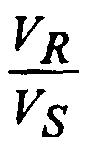
- the voltage ratio is greatly impacted by ⁇ , as shown in Figure 2.
- V S equals V R .
- the full effect of the coating roller voltage V R as controlled by high voltage power supply 14 , is seen at the web surface and the maximum electrostatic force is exerted upon the coating liquid.
- a web surface having a longer characteristic electrical length ⁇ requires a higher coating roller voltage V R as compared to a web surface having a shorter characteristic electrical length ⁇ to obtain the same electrostatic force upon the coating liquid.
- the characteristic electrical length For a voltage ratio of 2.54 or less the characteristic electrical length must be less than 100 ⁇ m. As the characteristic electrical length increases due, for example, to a lower web surface resistivity for a fixed web capacitance/area and web speed, the voltage ratio increases. For a voltage ratio of 8.5 or less, this length must be less than 400 ⁇ m. Therefore, to compensate for longer lengths ⁇ , as for webs having a higher surface conductivity, higher voltages must be used to achieve the same electrostatic force. This is undesirable as higher voltages may be more difficult to achieve or may result in arcing or unacceptable glow at the coating roller or higher web charges remaining after coating. Using equation 2 the characteristic electrical length is 93 ⁇ m.
- a set of webs was made having different values of surface resistivity on the surface to be coated.
- the range of surface resistivity values was estimated using equation 2 and given a web capacitance/area while on the coating roller of 28 pF/cm 2 (3.2 ⁇ 0 /100 ⁇ m), a web speed range of roughly 2.5 to 10 m/s, and a range of characteristic electrical lengths from 0.04 ⁇ m to 1400 ⁇ m based upon Figure 2. This range of surface resistivity was determined to be from 10 9 to 10 13 ohms/square. Surface resistivity was controlled via a tin oxide/gelatin layer on the web, which was a 100 ⁇ m thick polyester support.
- Tin oxide/gel subbing layers were coated both with and without incorporation of the surfactant saponin. These subbing layers were subsequently coated upon with an 11.8% aqueous mixture of gelatin at a flow rate per unit width of 4 cm 2 /s.
- the curtain coating method was used with a curtain height of approximately 10 inches and application angle at the coating roller of +15 degrees. The coating roller voltage required to eliminate air entrainment for a given speed was measured as a function of web surface resistivity.
- the desired web surface voltage V S was taken to be roughly constant with distance upstream of the coating point (x) and equal to the coating roller voltage V R , obtained when coating a relatively insulative web having a characteristic electrical length of less than 5 ⁇ m, for a given combination of speed and surfactant level.
- Figure 3 presents the results obtained with these supports having different characteristic electrical lengths, for three different coating speeds, 5.5, 6.5 and 7.5 m/s. Results are shown for supports having a wide range of surface resistance (characteristic electrical length). Also plotted in Figure 3 are the predicted voltage ratio of as a function of ⁇ for three different distances x upstream of the coating point, -25, -50 and -100 ⁇ m, using equation 1 provided above. The voltage ratio required to maintain a given maximum coating speed before air entrainment increases with characteristic electrical length (decreasing surface resistivity). This relationship follows the dependence shown in Figure 2. Also, this relationship is independent of the presence of surfactant (hollow symbols), or lack thereof (filled symbols), in the subbing layer.
- Uniform coatings without air entrainment were achieved at ⁇ 400 ⁇ m and more robustly at ⁇ 100 ⁇ m at coating roller voltages low enough to minimize arcing and glow during or after coating and to minimize formation of electrostatic charge remaining on the back side of the web after coating.
- the new support differs from the existing one only in the fact that the surface to be coated has a different subbing layer.
- the surface resistivity must be greater than 10 9.58 ohms/square if the product is to be coated at 7.5 m/s.
- Knowledge of the surface resistivity of the subbing layer as a function of tin-oxide concentration allows the designer to determine allowable ranges of tin-oxide concentration that will permit the coating process to successfully operate at coating roller voltages less than or equal to 1500 V.
- Determination and control of the characteristic electrical length of the surface of a web to be coated is extremely helpful in setting the levels of electrostatic assist for a desired coating speed.
- This length can be independent of the presence of surfactants in a subbing layer as well as independent of the web temperature prior to coating.
- the benefits of minimizing the characteristic electrical length lie in the concomitant minimization of the voltage needed to provide the assist, resulting in reduced opportunities for arcing and glow at or near the coating point and little or no electrostatic charge remaining on the web after coating.
- the above results are not limited to coating method, being equally applicable to methods other than curtain coating, such as bead or extrusion coating.
- the electrostatic force may be derived from charge deposited on the web prior to the coating point, in conjunction with or instead of an electrified coating roller.
- a method for coating a liquid composition to a web substrate at a coating application point while moving in contact with and around a coating roller to form a coating on a surface of the web substrate comprising the steps of:
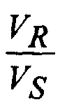
- a method wherein is less than 2 for -100 ⁇ m ⁇ x ⁇ 0 ⁇ m.
- a method wherein said delivered liquid composition is a photosensitive material.
- a method wherein said web substrate is selected from the group consisting of polyester film, cellulose acetate film, and plastic-coated paper.
- a method comprising the additional step of coating said web substrate with a gelatin subbing layer prior to said applying step.
- gelatin subbing layer includes a surfactant
Landscapes
- Chemical & Material Sciences (AREA)
- Engineering & Computer Science (AREA)
- Materials Engineering (AREA)
- Physics & Mathematics (AREA)
- General Physics & Mathematics (AREA)
- Application Of Or Painting With Fluid Materials (AREA)
Abstract
Description
- This invention relates generally to methods for coating liquids onto moving substrates, more particularly to methods for increasing the coating speed and uniformity of mixtures or solutions using electrostatic assistance.
- This invention relates in general to the art of coating and in particular to an improved method for carrying out a process of coating in which one or more layers of coating composition, preferably a conductive composition, are applied to the surface of a substrate by advancing the substrate through a coating zone in which a flow coating composition is applied thereto, for example, a process of bead coating or a process of curtain coating. More specifically, this invention relates to an improved coating method in the manufacturing of a photographic film, photographic paper, photographic printing layer, a magnetic recording tape, an adhesive tape, pressure-sensitive recording layer, an offset printing plate material or the like.
- A method of applying an electrostatic force to assist in a coating method, along with a conventional method of coating a continuously moving web, has been previously disclosed. For example, as disclosed by Hartman in WO 89/05477, ionizers may be used to deposit polar charge on the web prior to the coating application locus to generate an electrostatic field at the coating application locus for a curtain coating method. This electrostatic assist enables the coating method to operate at increased speeds without the defect of air bubbles trapped in the coating layers or between the web and the coated layer. Many prior patents are cited by Hartman discussing the use of polar charge assist in a bead coating method, as well as methods of measuring and controlling the electrostatic field so that a uniform charge of the required magnitude is obtained. These patents do not describe any particular electrical properties of the web that are particularly helpful to the use of electrostatic assist for a coating method.
- In another example disclosed in US-A-3,335,026, a potential difference is applied between the coating roller and the coating composition to generate an electrostatic field to attract the coating composition to the web. This patent constrains the resistivity of the web surface to be greater than 109 ohms/square. However, as is shown below in the description of the present invention, it is not the surface resistivity alone, but its combination with the web speed and web capacitance while on the coating roller that determines the effectiveness of the electrostatic assist. Thus, it is possible to use electrostatic assist for web surfaces having a resistivity less than 109 ohms/square. Furthermore, De Geest does not address the issue of designing a support with respect to surface resistivity and web capacitance so as to achieve a specified coating speed using electrostatic assist with minimized coating roller voltage levels. By minimized coating roller voltage levels it is meant that the voltage level is preferably as close as possible to the voltage level required when using an insulating web having a surface resistivity greater than 1013 ohms/square.
- In another example disclosed in US-A-4,837,045, an electrostatic force on a coating composition is combined with a web having a gelatin-subbing layer containing a surfactant. This electrostatic force allows an increase in speed of coating without increasing the load of drying the coated layers. The gelatin-subbing layer is required to contain a surfactant to achieve the desired electrostatic assist.
- In another example disclosed in US-A-4,835,004, web temperature control is used to reduce the non-uniformity of and preserve the level of electrical charges deposited on the web by a set of ionizers prior to the coating application locus. This uniform charge is then used to provide an electrostatic assist for the coating method to yield defect-free coatings. This patent places certain requirements on the environment (temperature, relative humidity (RH)) of the web prior to the coating application locus to achieve a uniform charge.
- Thus, there is a need for a method for coating emulsions at high speeds without having air bubbles entrained in the coated layer and with no loss in adherence using electrostatic assist regardless of the presence, or absence, of surfactants in a gelatin subbing layer and without placing restrictions on the environment of the web prior to the coating application locus.
- Accordingly, several objects and advantages of the present invention are:
- 1) to provide a coating method that utilizes an electrostatic force to increase coating speed without modifying the coating composition and without suffering from entrained air bubbles in the coated layers or between the web and the coated layers;
- 2) to provide a coating method that ensures the existence of an electrostatic force at the coating application locus without the need for surfactant-containing gelatin subbing layers;
- 3) to provide a methodology for designing a support with respect to surface resistivity and web capacitance so as to achieve a specified coating speed using electrostatic assist with minimized coating roller voltage levels.;
- 4) to minimize the voltage or charge level required at the coating point for a desired electrostatic force to minimize the possibility of arcing and glow during or after coating and to minimize electrostatic charge remaining on the web after coating.
-
- The above and other objects of the present invention can be achieved through use of a fundamental parameter, the characteristic electrical length, λ, expressed in micrometers (µm), determined by the electrical properties of the web and the coating speed of the web. The relationship of λ to a voltage applied to the coating roller, as shown in Figures 2 and 3, permits for the first time the calculated placement of an intended coating at an optimally robust level of electrostatic assist.
- The characteristic electrical length is defined as the reciprocal of the product of the web surface resistance (ohms/square), web capacitance while on the coating roller (F/m2) - defined as the ratio of the web permittivity (F/m) divided by the web thickness (m), and the web speed (m/s). A characteristic electrical length less than 400 µm, and preferably less than 100 µm, is desirable. When meeting this criterion, the web surface voltage in the vicinity of the coating point (within 100 µm) remains at a level sufficient to apply a significant electrostatic force on the coating composition. This criterion is independent of whether the electrostatic force is applied via polar charge deposited on the web or a potential difference applied between the coating roller and the coating composition or a combination of these two methods.
- The failure mode of entrained air in the coating is encountered at some point as coating speed is increased. This failure mode can be suppressed until higher speeds by the application of an electrostatic force between the fluid and web. Achieving this force requires an electrostatic charge or electrostatic voltage source as well as some constraints on the electromechanical properties of the web, both bulk and surface-to-be-coated. The present invention properly provides these constraints, ensuring the full effectiveness of the electrostatic charge or voltage. Coatings made in accordance with the invention are not dependent upon the use of any particular surfactant in the gelatin layer on the surface of a web to be coated, nor are they dependent upon control of the environment (RH, temperature) the web encounters prior to the coating process.
- The foregoing and other objectives, features, and advantages of the invention, as well as presently preferred embodiments thereof, will become more apparent from a reading of the following description in connection with the accompanying drawings in which:
- Figure 1 is a schematic vertical cross-sectional view of an apparatus for coating in accordance with a method of the invention;
- Figure 2 is a graph showing the dependence of the ratio of the voltage applied to the coating roller (VR) to the voltage on the web surface (VS) as a function of the characteristic electrical length (λ) of the web surface to be coated; and
- Figure 3 is a graph showing data from various coatings with and without surfactant superimposed on characteristic curves like that shown in Fig. 2 for three different distances upstream of the coating locus.
-
- As shown in Figure 1, a
web 10 is conveyed around acoating roller 12.Coating roller 12 is electrically isolated and connected to a highvoltage power supply 14. Acoating fluid 16 flows over aninclined surface 18 of acoating die 20 and falls freely in a thin film over theedge 22 of the die, forming acurtain 24. Curtain 24 falls by gravity and impinges on the continuously movingweb 10 atcoating application point 26 resulting in acontinuous coating 28. -
Web 10 may be a plastic film, a plain paper, a plastic-coated paper, synthetic paper, glass, cloth, ceramic or any other dielectric material capable of maintaining an electrostatic potential difference between opposite surfaces thereof. The plastic film may be composed of, for example, a polyolefin such as polyethylene and polypropylene; a vinyl polymer such as polyvinyl acetate, polyvinyl chloride and polystyrene; a polyamide such as 6,6-nylon and 6-nylon; a polyester such as polyethylene terephthalate and polyethylene-2,6-naphthalate, polycarbonate; a cellulose acetate such as cellulose triacetate and cellulose diacetate; a cellulose nitrate; or the like. The plastic used for a plastic-coated paper may be an alpha-olefin, as exemplified by polyethylene and polypropylene, but is not confined thereto. Theweb 10 may have one or several layers previously coated on top of the base support. - To improve adhesion of the coating composition to the surface of
web 10 the surface to be coated may have undergone an electrical discharge treatment and may have a subbing layer on top of the base web material described above. The discharge treatment may be a corona discharge treatment or a glow discharge treatment or an atmospheric glow discharge treatment. The subbing layer may contain gelatin or other polymeric binders as well as a surfactant, surfactants being typically added to aid in the coating of the subbing composition during the base manufacturing process. - The composition of the coating liquid may be varied according to the use thereof. For example, the liquid may be used to form a photosensitive emulsion layer, undercoating layer, protective layer, backing layer, antistatic or antihalation layer, or the like of a photographic photosensitive material, an ink-absorbing layer in the case of inkjet receiver media, a magnetic layer, undercoating layer, lubricant layer, protective layer, backing layer or the like of a magnetic recording medium, an adhesive layer, a coloring layer, an anti-rusting layer or the like. The coating composition can contain a water-soluble binder or an organic solvent-soluble binder.
- Various types of surfactants in the coating composition can be used to modify the surface tension and coatability of the coating composition in accordance with this invention. Useful surfactants include saponin; non-ionic surfactants such as polyalkylene oxides, for example, polyethylene oxides, and the water-soluble adducts of glycidol and alkyl phenol; anionic surfactants such as alkyaryl polyether sulfates and sulfonates; and amphoteric surfactants such as arylalkyl taurines, N-alkyl and N-acyl beta-amino propionates; alkyl ammonium sulfonic acid betaines, and so forth
- The coating method may be a slide coating method, a roller bead coating method, a spray coating method, an extrusive coating method, a curtain coating method, or the like.
- Given that the coating die is at ground potential and the coating composition is conductive enough to be considered at ground potential also, the voltage distribution on the surface of a web to be coated (VS), while on a coating roller raised to a high voltage, and prior to the coating point, is determined by the applied coating roller voltage (VR) in the following manner:
- The critical parameter λ is determined by the following formula
- The voltage ratiois greatly impacted by λ, as shown in Figure 2. The plot shows the ratio of the voltage applied to the coating roller (VR) to the voltage at the web surface (VS) as a function of characteristic electrical length λ of the web surface to be coated, evaluated at a location 50 µm upstream from the coating point (x = -50 µm). For short characteristic electrical lengths, small λ, such as those given by insulating webs, VS equals VR. The full effect of the coating roller voltage VR, as controlled by high

voltage power supply 14, is seen at the web surface and the maximum electrostatic force is exerted upon the coating liquid. For longer lengths, larger λ, the roller voltage VR must be increased in order to maintain the same web surface voltage VS and hence, the same electrostatic force upon the coating liquid. Therefore, a web surface having a longer characteristic electrical length λ requires a higher coating roller voltage VR as compared to a web surface having a shorter characteristic electrical length λ to obtain the same electrostatic force upon the coating liquid. - For a voltage ratio of 2.54 or less the characteristic electrical length must be less than 100 µm. As the characteristic electrical length increases due, for example, to a lower web surface resistivity for a fixed web capacitance/area and web speed, the voltage ratio increases. For a voltage ratio of 8.5 or less, this length must be less than 400 µm. Therefore, to compensate for longer lengths λ, as for webs having a higher surface conductivity, higher voltages must be used to achieve the same electrostatic force. This is undesirable as higher voltages may be more difficult to achieve or may result in arcing or unacceptable glow at the coating roller or higher web charges remaining after coating. Using
equation 2 the characteristic electrical length is 93 µm. - A set of webs was made having different values of surface resistivity on the surface to be coated. The range of surface resistivity values was estimated using
equation 2 and given a web capacitance/area while on the coating roller of 28 pF/cm2 (3.2ε0/100 µm), a web speed range of roughly 2.5 to 10 m/s, and a range of characteristic electrical lengths from 0.04 µm to 1400 µm based upon Figure 2. This range of surface resistivity was determined to be from 109 to 1013 ohms/square. Surface resistivity was controlled via a tin oxide/gelatin layer on the web, which was a 100 µm thick polyester support. For the tin oxide/gel ratio used, this layer is relatively insensitive to ambient RH, providing a constant surface resistivity as the web approached the coating point. Tin oxide/gel subbing layers were coated both with and without incorporation of the surfactant saponin. These subbing layers were subsequently coated upon with an 11.8% aqueous mixture of gelatin at a flow rate per unit width of 4 cm2/s. The curtain coating method was used with a curtain height of approximately 10 inches and application angle at the coating roller of +15 degrees. The coating roller voltage required to eliminate air entrainment for a given speed was measured as a function of web surface resistivity. The desired web surface voltage VS was taken to be roughly constant with distance upstream of the coating point (x) and equal to the coating roller voltage VR, obtained when coating a relatively insulative web having a characteristic electrical length of less than 5 µm, for a given combination of speed and surfactant level. - Figure 3 presents the results obtained with these supports having different characteristic electrical lengths, for three different coating speeds, 5.5, 6.5 and 7.5 m/s. Results are shown for supports having a wide range of surface resistance (characteristic electrical length). Also plotted in Figure 3 are the predicted voltage ratio ofas a function of λ for three different distances x upstream of the coating point, -25, -50 and -100 µm, using
equation 1 provided above. The voltage ratio required to maintain a given maximum coating speed before air entrainment increases with characteristic electrical length (decreasing surface resistivity). This relationship follows the dependence shown in Figure 2. Also, this relationship is independent of the presence of surfactant (hollow symbols), or lack thereof (filled symbols), in the subbing layer. Uniform coatings without air entrainment were achieved at λ<400 µm and more robustly at λ<100 µm at coating roller voltages low enough to minimize arcing and glow during or after coating and to minimize formation of electrostatic charge remaining on the back side of the web after coating. - For an existing product it is desirable to replace an existing 100 µm thick polyester web support with a new support. The existing product is successfully curtain-coated at 7.5 m/s with the benefit of electrostatic assist, using a coating roller voltage of 800V. Given a web capacitance/area of 28 pF/cm2 (3.2ε0/100 µm), while on the coating roller, and a surface resistivity of 1013 ohms/square, the characteristic electrical length for this application is 0.05
µm using equation 2 provided above. Therefore, usingequation 1 the web surface voltage at the coating point equals the coating roller voltage at upstream distances close to the coating application point (within 50 µm to 100 µm). - The new support differs from the existing one only in the fact that the surface to be coated has a different subbing layer, having a lower resistivity of 109.82 ohms/square. It is desirable to maintain the 7.5 m/s coating process speed with the same coating hardware setup and electrostatic assist. However, due to the decrease in surface resistivity, the characteristic electrical length has now increased to 71
µm using equation 2. Using Fig. 2 orequation 1 with x=-50 µm,which implies that the coating roller voltage will have to be roughly doubled to 1600V in order to achieve the same web surface voltage, and electrostatic assist force on the coating liquid.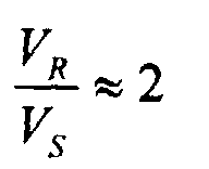
- For an existing product it is desirable to replace an existing 100 µm thick polyester web support with a new support. The existing product is successfully curtain-coated at 7.5 m/s with the benefit of electrostatic assist, using a coating roller voltage of 500V. Given a web capacitance/area of 28 pF/cm2 (3.2ε0/100 µm), while on the coating roller, and a surface resistivity of 1013 ohms/square, the characteristic electrical length for this application is 0.05
µm using equation 2 provided above. Therefore, usingequation 1 the web surface voltage at the coating point equals the coating roller voltage at upstream distances close to the coating application point (within 50 µm to 100 µm). - The new support differs from the existing one only in the fact that the surface to be coated has a different subbing layer. The surface resistivity of this subbing layer is known to vary with the level of a constituent, tin-oxide, added to the subbing layer. It is also known that for coating roller voltages beyond 1500V, the coating machine used to make this product experiences arcing from the coating roller to surrounding equipment. Therefore, it is desirable to design the subbing layer such that voltages ≤1500V are capable of producing uniform coatings at 7.5 m/s with the same coating hardware setup. Therefore,or 3.0. From Figure 2 or using
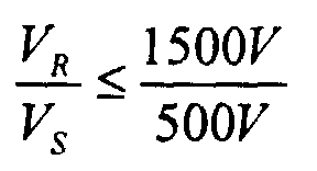
equation 1 with x=-50 µm, this implies the characteristic electrical length must be less than or equal to 124 µm. FromEquation 2 it can be found that the surface resistivity must be greater than 109.58 ohms/square if the product is to be coated at 7.5 m/s. Knowledge of the surface resistivity of the subbing layer as a function of tin-oxide concentration allows the designer to determine allowable ranges of tin-oxide concentration that will permit the coating process to successfully operate at coating roller voltages less than or equal to 1500 V. - Determination and control of the characteristic electrical length of the surface of a web to be coated is extremely helpful in setting the levels of electrostatic assist for a desired coating speed. This length can be independent of the presence of surfactants in a subbing layer as well as independent of the web temperature prior to coating. The benefits of minimizing the characteristic electrical length lie in the concomitant minimization of the voltage needed to provide the assist, resulting in reduced opportunities for arcing and glow at or near the coating point and little or no electrostatic charge remaining on the web after coating.
- The above results and corresponding dependence upon surface resistivity are also true for variations in web speed or web capacitance due to their effect upon the characteristic electrical length.
- The above results are not limited to coating method, being equally applicable to methods other than curtain coating, such as bead or extrusion coating. In addition, the electrostatic force may be derived from charge deposited on the web prior to the coating point, in conjunction with or instead of an electrified coating roller.
- From the foregoing description, it will be apparent that there has been provided an improved method for coating a liquid to a web to form a uniform coated layer, wherein a novel calculable coating parameter, the characteristic electrical length, may be predetermined to provide an intended coating with an optimally robust level of electrostatic assist. Variations and modifications of the herein described coating method within the scope of the invention will undoubtedly suggest themselves to those skilled in this art. Accordingly, the foregoing description should be taken as illustrative and not in a limiting sense.
- Other features of the invention are included below.
- A method for coating a liquid composition to a web substrate at a coating application point while moving in contact with and around a coating roller to form a coating on a surface of the web substrate, comprising the steps of:
- a) setting a characteristic electrical length (λ) to be less than about 400 µm by varying one or more of the parameters of the surface resistance (ρS) on the surface of the web substrate to be coated, the web capacitance per unit area (C) of the web substrate in contact with the coating roller, and the coating speed (U) for said web substrate wherein λ is determined by the equation λ=(ρSCU)-1;
- b) controlling the voltage on the surface of the web (VS) by controlling both the voltage applied to the coating roller (VR) and the charge applied to the web surface prior to the coating point (Vweb) using the equation VS = (VR + Vweb)(1 - ex /λ) wherein e is a constant and x is a distance before the coating application point on the web substrate and is in the range of from about 50 µm to about 100 µm; and
- c) delivering said liquid composition to said web substrate at said coating application point traveling at said speed U to form a coated web substrate.
-
- A method wherein λ is less than 100 µm.
- A method whereinis less than 2 for -100 µm ≤ x ≤ 0 µm.

- A method wherein electrostatic charges are placed on the surface of said web substrate prior to said applying step to provide an electrostatic force.
- A method wherein electrostatic charges are placed on the coating roller prior to and during said applying step to provide an electrostatic force.
- A method wherein a voltage differential is established between a coating roller and said liquid composition during said applying step to provide an electrostatic force.
- A method wherein said delivered liquid composition is a photosensitive material.
- A method wherein said web substrate is selected from the group consisting of polyester film, cellulose acetate film, and plastic-coated paper.
- A method comprising the additional step of coating said web substrate with a gelatin subbing layer prior to said applying step.
- A method wherein said gelatin subbing layer includes a surfactant.
Claims (10)
- A method for coating a liquid composition to a web substrate at a coating application point while moving in contact with and around a coating roller to form a coating on a surface of the web substrate, comprising the steps of:a) setting a characteristic electrical length (λ) to be less than about 400 µm by varying one or more of the parameters of the surface resistance (ρS) on the surface of the web substrate to be coated, the web capacitance per unit area (C) of the web substrate in contact with the coating roller, and the coating speed (U) for said web substrate wherein λ is determined by the equation λ=(ρSCU)-1;b) controlling the voltage on the surface of the web (VS) by controlling the voltage applied to the coating roller (VR) using the equation VS = VR (1 - ex /λ) wherein e is a constant and x is a distance before the coating application point on the web substrate and is in the range of from about 50 µm to about 100 µm; andc) delivering said liquid composition from a coating die to said web substrate at said coating application point traveling at said speed U to form a coated web substrate.
- A method in accordance with claim 1 wherein λ is less than 100 µm.
- A method in accordance with claim 1 whereinis less than 2 for -100 µm ≤ x ≤ 0 µm.
- A method in accordance with claim 1 wherein electrostatic charges are placed on the surface of said web substrate prior to said applying step to provide an electrostatic force.
- A method in accordance with claim 1 wherein electrostatic charges are placed on the coating roller prior to and during said applying step to provide an electrostatic force.
- A method in accordance with claim 1 wherein a voltage differential is established between a coating roller and said liquid composition during said applying step to provide an electrostatic force.
- A method in accordance with claim 1 wherein said delivered liquid composition is a photosensitive material.
- A method in accordance with claim 1 wherein said web substrate is selected from the group consisting of polyester film, cellulose acetate film, and plastic-coated paper.
- A method in accordance with claim 1 comprising the additional step of coating said web substrate with a gelatin subbing layer prior to said applying step.
- A method in accordance with claim 9 wherein said gelatin subbing layer includes a surfactant.
Applications Claiming Priority (2)
| Application Number | Priority Date | Filing Date | Title |
|---|---|---|---|
| US09/408,221 US6171658B1 (en) | 1998-02-06 | 1999-09-29 | Coating method using electrostatic assist |
| US408221 | 1999-09-29 |
Publications (2)
| Publication Number | Publication Date |
|---|---|
| EP1088596A1 true EP1088596A1 (en) | 2001-04-04 |
| EP1088596B1 EP1088596B1 (en) | 2003-11-26 |
Family
ID=23615360
Family Applications (1)
| Application Number | Title | Priority Date | Filing Date |
|---|---|---|---|
| EP00203226A Expired - Lifetime EP1088596B1 (en) | 1999-09-29 | 2000-09-18 | Coating method using electrostatic assist |
Country Status (3)
| Country | Link |
|---|---|
| US (1) | US6171658B1 (en) |
| EP (1) | EP1088596B1 (en) |
| DE (1) | DE60006764T2 (en) |
Families Citing this family (4)
| Publication number | Priority date | Publication date | Assignee | Title |
|---|---|---|---|---|
| US6368675B1 (en) | 2000-04-06 | 2002-04-09 | 3M Innovative Properties Company | Electrostatically assisted coating method and apparatus with focused electrode field |
| DE60111632T2 (en) * | 2000-04-06 | 2006-05-18 | 3M Innovative Properties Co., Saint Paul | ELECTROCATED COATING METHOD AND DEVICE WITH FOCUSED ELECTRODE FIELD |
| US6475572B2 (en) | 2000-04-06 | 2002-11-05 | 3M Innovative Properties Company | Electrostatically assisted coating method with focused web-borne charges |
| JP5920479B2 (en) * | 2012-09-28 | 2016-05-25 | 日産自動車株式会社 | Coating device |
Citations (2)
| Publication number | Priority date | Publication date | Assignee | Title |
|---|---|---|---|---|
| WO1992011572A1 (en) * | 1990-12-20 | 1992-07-09 | Eastman Kodak Company | Improvements in or relating to coating |
| EP0728532A1 (en) * | 1995-02-25 | 1996-08-28 | Kodak Limited | Curtain coating process |
Family Cites Families (5)
| Publication number | Priority date | Publication date | Assignee | Title |
|---|---|---|---|---|
| US3335026A (en) * | 1963-07-16 | 1967-08-08 | Gevaert Photo Prod Nv | Method for coating liquid compositions employing electrostatic field |
| US3730753A (en) * | 1971-07-30 | 1973-05-01 | Eastman Kodak Co | Method for treating a web |
| JPH069671B2 (en) * | 1986-06-25 | 1994-02-09 | 富士写真フイルム株式会社 | Application method |
| JPH0625854B2 (en) * | 1987-07-17 | 1994-04-06 | 富士写真フイルム株式会社 | Application method |
| DE3780472T2 (en) * | 1987-12-03 | 1993-03-11 | Eastman Kodak Co | METHOD AND DEVICE FOR QUICK COATING BY THE CURRENT PROCEDURE. |
-
1999
- 1999-09-29 US US09/408,221 patent/US6171658B1/en not_active Expired - Lifetime
-
2000
- 2000-09-18 EP EP00203226A patent/EP1088596B1/en not_active Expired - Lifetime
- 2000-09-18 DE DE60006764T patent/DE60006764T2/en not_active Expired - Fee Related
Patent Citations (2)
| Publication number | Priority date | Publication date | Assignee | Title |
|---|---|---|---|---|
| WO1992011572A1 (en) * | 1990-12-20 | 1992-07-09 | Eastman Kodak Company | Improvements in or relating to coating |
| EP0728532A1 (en) * | 1995-02-25 | 1996-08-28 | Kodak Limited | Curtain coating process |
Also Published As
| Publication number | Publication date |
|---|---|
| DE60006764D1 (en) | 2004-01-08 |
| DE60006764T2 (en) | 2004-09-30 |
| US6171658B1 (en) | 2001-01-09 |
| EP1088596B1 (en) | 2003-11-26 |
Similar Documents
| Publication | Publication Date | Title |
|---|---|---|
| JP4326711B2 (en) | Curtain application method | |
| JP2575579B2 (en) | Slide bead coating apparatus and photographic member forming method | |
| US5295039A (en) | Method of applying single polar electro-static charges to continuously travelling long web support, and apparatus practicing same | |
| EP0530752B1 (en) | Coating apparatus and method | |
| EP1088596B1 (en) | Coating method using electrostatic assist | |
| AU688194B2 (en) | Method Of Curtain Coating A Moving Support Wherein The Maximum Practical Coating Speed Is Increased | |
| EP1274515B1 (en) | Electrostatically assisted coating method and apparatus with focused web charge field | |
| US6524660B2 (en) | System for coating using a grooved backing roller and electrostatic assist | |
| US6177141B1 (en) | Method for coating a liquid composition to a web using a backing roller with a relieved surface | |
| US6716286B2 (en) | Electrostatically assisted coating method and apparatus with focused electrode field | |
| US6511711B2 (en) | Slide bead coating method | |
| US6517909B1 (en) | Method for using a patterned backing roller for curtain coating a liquid composition to a web | |
| US6475572B2 (en) | Electrostatically assisted coating method with focused web-borne charges | |
| US6638576B2 (en) | Apparatus and method of coating a web | |
| JPH10506048A (en) | Electrostatic system for controlling the flow of fluid after coating on a substrate | |
| US6242051B1 (en) | Coating method using electrostatic assist | |
| US6630208B2 (en) | Use of subbing layer in web coating | |
| JPH03123669A (en) | Coating method | |
| JP2597237B2 (en) | Application method | |
| JPH06106121A (en) | Coating method and apparatus | |
| JPH10113605A (en) | Curtain coating application method | |
| JP2670910B2 (en) | Application method | |
| JP2001334206A (en) | Method for applying coating liquid to web with joint | |
| JPH0494764A (en) | Coating method |
Legal Events
| Date | Code | Title | Description |
|---|---|---|---|
| PUAI | Public reference made under article 153(3) epc to a published international application that has entered the european phase |
Free format text: ORIGINAL CODE: 0009012 |
|
| AK | Designated contracting states |
Kind code of ref document: A1 Designated state(s): BE DE NL |
|
| AX | Request for extension of the european patent |
Free format text: AL;LT;LV;MK;RO;SI |
|
| 17P | Request for examination filed |
Effective date: 20010912 |
|
| AKX | Designation fees paid |
Free format text: BE DE NL |
|
| 17Q | First examination report despatched |
Effective date: 20030217 |
|
| GRAH | Despatch of communication of intention to grant a patent |
Free format text: ORIGINAL CODE: EPIDOS IGRA |
|
| GRAS | Grant fee paid |
Free format text: ORIGINAL CODE: EPIDOSNIGR3 |
|
| GRAA | (expected) grant |
Free format text: ORIGINAL CODE: 0009210 |
|
| AK | Designated contracting states |
Kind code of ref document: B1 Designated state(s): BE DE NL |
|
| REF | Corresponds to: |
Ref document number: 60006764 Country of ref document: DE Date of ref document: 20040108 Kind code of ref document: P |
|
| PGFP | Annual fee paid to national office [announced via postgrant information from national office to epo] |
Ref country code: NL Payment date: 20040809 Year of fee payment: 5 |
|
| PGFP | Annual fee paid to national office [announced via postgrant information from national office to epo] |
Ref country code: BE Payment date: 20040928 Year of fee payment: 5 |
|
| PGFP | Annual fee paid to national office [announced via postgrant information from national office to epo] |
Ref country code: DE Payment date: 20040930 Year of fee payment: 5 |
|
| PLBE | No opposition filed within time limit |
Free format text: ORIGINAL CODE: 0009261 |
|
| STAA | Information on the status of an ep patent application or granted ep patent |
Free format text: STATUS: NO OPPOSITION FILED WITHIN TIME LIMIT |
|
| 26N | No opposition filed |
Effective date: 20040827 |
|
| PG25 | Lapsed in a contracting state [announced via postgrant information from national office to epo] |
Ref country code: BE Free format text: LAPSE BECAUSE OF NON-PAYMENT OF DUE FEES Effective date: 20050930 |
|
| PG25 | Lapsed in a contracting state [announced via postgrant information from national office to epo] |
Ref country code: NL Free format text: LAPSE BECAUSE OF NON-PAYMENT OF DUE FEES Effective date: 20060401 Ref country code: DE Free format text: LAPSE BECAUSE OF NON-PAYMENT OF DUE FEES Effective date: 20060401 |
|
| NLV4 | Nl: lapsed or anulled due to non-payment of the annual fee |
Effective date: 20060401 |
|
| BERE | Be: lapsed |
Owner name: *EASTMAN KODAK CY Effective date: 20050930 |