EP1087621A2 - Apparatus and method for control of digital equipment - Google Patents
Apparatus and method for control of digital equipment Download PDFInfo
- Publication number
- EP1087621A2 EP1087621A2 EP00402601A EP00402601A EP1087621A2 EP 1087621 A2 EP1087621 A2 EP 1087621A2 EP 00402601 A EP00402601 A EP 00402601A EP 00402601 A EP00402601 A EP 00402601A EP 1087621 A2 EP1087621 A2 EP 1087621A2
- Authority
- EP
- European Patent Office
- Prior art keywords
- frame
- command
- digital equipment
- digital
- response frame
- Prior art date
- Legal status (The legal status is an assumption and is not a legal conclusion. Google has not performed a legal analysis and makes no representation as to the accuracy of the status listed.)
- Withdrawn
Links
Images



Classifications
-
- G—PHYSICS
- G06—COMPUTING OR CALCULATING; COUNTING
- G06F—ELECTRIC DIGITAL DATA PROCESSING
- G06F3/00—Input arrangements for transferring data to be processed into a form capable of being handled by the computer; Output arrangements for transferring data from processing unit to output unit, e.g. interface arrangements
-
- H—ELECTRICITY
- H04—ELECTRIC COMMUNICATION TECHNIQUE
- H04L—TRANSMISSION OF DIGITAL INFORMATION, e.g. TELEGRAPHIC COMMUNICATION
- H04L12/00—Data switching networks
- H04L12/28—Data switching networks characterised by path configuration, e.g. LAN [Local Area Networks] or WAN [Wide Area Networks]
- H04L12/40—Bus networks
- H04L12/40052—High-speed IEEE 1394 serial bus
- H04L12/40117—Interconnection of audio or video/imaging devices
-
- H—ELECTRICITY
- H04—ELECTRIC COMMUNICATION TECHNIQUE
- H04L—TRANSMISSION OF DIGITAL INFORMATION, e.g. TELEGRAPHIC COMMUNICATION
- H04L12/00—Data switching networks
- H04L12/28—Data switching networks characterised by path configuration, e.g. LAN [Local Area Networks] or WAN [Wide Area Networks]
- H04L12/40—Bus networks
- H04L12/40052—High-speed IEEE 1394 serial bus
- H04L12/40071—Packet processing; Packet format
-
- H—ELECTRICITY
- H04—ELECTRIC COMMUNICATION TECHNIQUE
- H04N—PICTORIAL COMMUNICATION, e.g. TELEVISION
- H04N21/00—Selective content distribution, e.g. interactive television or video on demand [VOD]
- H04N21/40—Client devices specifically adapted for the reception of or interaction with content, e.g. set-top-box [STB]; Operations thereof
- H04N21/41—Structure of client; Structure of client peripherals
- H04N21/4104—Peripherals receiving signals from specially adapted client devices
- H04N21/4108—Peripherals receiving signals from specially adapted client devices characterised by an identification number or address, e.g. local network address
-
- H—ELECTRICITY
- H04—ELECTRIC COMMUNICATION TECHNIQUE
- H04N—PICTORIAL COMMUNICATION, e.g. TELEVISION
- H04N21/00—Selective content distribution, e.g. interactive television or video on demand [VOD]
- H04N21/40—Client devices specifically adapted for the reception of or interaction with content, e.g. set-top-box [STB]; Operations thereof
- H04N21/43—Processing of content or additional data, e.g. demultiplexing additional data from a digital video stream; Elementary client operations, e.g. monitoring of home network or synchronising decoder's clock; Client middleware
- H04N21/436—Interfacing a local distribution network, e.g. communicating with another STB or one or more peripheral devices inside the home
- H04N21/43615—Interfacing a Home Network, e.g. for connecting the client to a plurality of peripherals
-
- H—ELECTRICITY
- H04—ELECTRIC COMMUNICATION TECHNIQUE
- H04N—PICTORIAL COMMUNICATION, e.g. TELEVISION
- H04N21/00—Selective content distribution, e.g. interactive television or video on demand [VOD]
- H04N21/40—Client devices specifically adapted for the reception of or interaction with content, e.g. set-top-box [STB]; Operations thereof
- H04N21/43—Processing of content or additional data, e.g. demultiplexing additional data from a digital video stream; Elementary client operations, e.g. monitoring of home network or synchronising decoder's clock; Client middleware
- H04N21/436—Interfacing a local distribution network, e.g. communicating with another STB or one or more peripheral devices inside the home
- H04N21/4363—Adapting the video stream to a specific local network, e.g. a Bluetooth® network
- H04N21/43632—Adapting the video stream to a specific local network, e.g. a Bluetooth® network involving a wired protocol, e.g. IEEE 1394
-
- H—ELECTRICITY
- H04—ELECTRIC COMMUNICATION TECHNIQUE
- H04N—PICTORIAL COMMUNICATION, e.g. TELEVISION
- H04N5/00—Details of television systems
- H04N5/76—Television signal recording
- H04N5/765—Interface circuits between an apparatus for recording and another apparatus
-
- H—ELECTRICITY
- H04—ELECTRIC COMMUNICATION TECHNIQUE
- H04N—PICTORIAL COMMUNICATION, e.g. TELEVISION
- H04N5/00—Details of television systems
- H04N5/76—Television signal recording
- H04N5/91—Television signal processing therefor
- H04N5/92—Transformation of the television signal for recording, e.g. modulation, frequency changing; Inverse transformation for playback
- H04N5/926—Transformation of the television signal for recording, e.g. modulation, frequency changing; Inverse transformation for playback by pulse code modulation
Definitions
- the present invention relates to an apparatus and method for generating a command frame and/or a response frame transmitted and received to/from a digital equipment connected to a digital interface, and more particularly, to an apparatus and method for generating a command frame and/or a response frame for the control of a digital equipment which is capable of easily generating a command frame and/or a response frame of a size appropriate for the digital equipment.
- a command frame and/or response frame transmitted and received to/from a digital equipment connected to a digital interface is generated in the form appropriate for the type of a digital equipment by searching command and/or response frame identification codes stored by means of a control signal according to the type of the digital equipment inputted by an user.
- the generated command and/or response frame is transmitted to the corresponding a digital equipment.
- FIG. 1 is a block diagram illustrating a digital equipment connected to a digital interface according to the conventional art, wherein a variety of a digital equipment such as a digital VCR(D-VCR or D-VHS) 100, digital television(D-TV) 110, digital audio(D-Audio) 120, DVD(Digital Versatile Disc) recorder/reproducer 130 is connected to the above-said digital interface.
- a digital equipment such as a digital VCR(D-VCR or D-VHS) 100, digital television(D-TV) 110, digital audio(D-Audio) 120, DVD(Digital Versatile Disc) recorder/reproducer 130 is connected to the above-said digital interface.
- the IEEE1 394 is used as the digital interface.
- Figure 2 is a block diagram of parts of a digital VCR(D-VCR or D-VHS) 100 and digital television(D-TV) 110 connected to a digital interface according to the conventional art.
- the above-said digital VCR 100 includes: a digital VCR processor 101 for receiving a signal inputted from the outside to process the same; a digital VCR program( D-VCR program) 102 constructed inside the digital VCR processor 101; a frame processing program 103 constructed inside the digital VCR program 102 for storing command and response frame formats according to the type of a digital equipment; and a digital interface processor (IEEE 1394 processor) 104 for generating the command and response frames appropriate for the digital equipment generated from the digital VCR processor 101 so as to be transmitted and received to/from a digital interface.
- a digital VCR processor 101 for receiving a signal inputted from the outside to process the same
- a digital VCR program( D-VCR program) 102 constructed inside the digital VCR processor 101
- a frame processing program 103 constructed inside the digital VCR program 102 for storing command and response frame formats according to the type of a digital equipment
- a digital interface processor IEEE 1394 processor
- the above digital television(D-TV) 110 is constructed in the same manner as the above-described digital VCR 100.
- the inputted signal is transmitted to the digital VCR processor(D-VCR processor) 101.
- the digital VCR processor 101 determines the command and/or response frame appropriate for the type of a corresponding a digital equipment, among command and/or response frames according to the type of a digital equipment pre-stored in a frame processing program 103 of the D-VCR program 102 by means of the above inputted signal.
- the determined command and/or response frame is transmitted to the IEEE 1394 processor 104 to thus be generated in the form appropriate for the transmission to the digital television 110, and the generated command and/or response frame is transmitted through an asynchronous channel of the IEEE 1394. Meanwhile, generated or received video/data data is transmitted through an isochronous channel of the IEEE 1394.
- the transmitted command and/or response frame is received from the IEEE 1394 processor 114 of the digital television 110.
- a digital TV processor 111 corresponding to the digital VCR processor 101 generate a command frame and/or a response frame in the same method as the above-described method for generating a command frame and/or a response frame for the digital VCR 100 to thus transmit the same to the asynchronous channel of the IEEE 1394, and the generated or received video/audio data is transmitted through the isochronous channel of the IEEE 1394.
- the command and/or response frame transmitted/received through the asynchronous channel is previously standardized according to the type of a digital equipment. Therefore, the method for generating a command frame and/or a response frame according to the conventional art has a problem that each of the command frame and response frame related to the type of a digital equipment connected to a digital interface must be repeatedly programmed.
- Figure 3 is a block diagram illustrating an apparatus for generating a command frame and/or a response frame transmitted/received through a digital interface according to the present invention.
- the apparatus includes: an input unit such as a keyboard 200 or remote control (R/C) 210 having a plurality of operation buttons; a host processor(main processor) 220 for outputting a digital equipment code and operation control signal upon receipt of a signal outputted from the input unit; a frame processor 230 for determining the type of a digital equipment and generating a command frame and response frame corresponding to the digital equipment upon receipt of the digital equipment code and operation control signal; a digital interface processor 250 for receiving the command frame and response frame and processing the same so as to be transmitted to the digital equipment connected to the digital interface; and a flash memory 240 for storing information on the format of the type of a digital equipment besides an internal memory of the frame processor 230.
- an input unit such as a keyboard 200 or remote control (R/C) 210 having a plurality of operation buttons
- a host processor(main processor) 220 for outputting a digital equipment code and operation control signal upon receipt of a signal outputted from the input unit
- a frame processor 230 for determining
- a host processor(main processor) 220 receives the inputted signal from the outside, and outputs a digital equipment code and operation control signal to the frame processor 230.
- the frame processor 230 determines the type of a digital equipment by means of an identification value recorded in the field of subunit type to be described in Figure 7, which corresponding to the received code value of the digital equipment.
- a command frame and/or a response frame corresponding to the type of the corresponding a digital equipment is determined by searching command and/or response frames pre-stored in the memory, and is transmitted to the host processor(main processor) 220.
- the command and/or response frame inputted to the host processor(main processor) 220 is outputted to the IEEE 1394 processor 250, and the outputted command and/or response framed is processed in such a manner that it is transmitted to the IEEE 1394, and is transmitted and received to/from an asynchronous channel of the IEEE 1394.
- the video/audio data reproduced or received from the host processor(main processor) 220 is transmitted and received through an isochronous channel of the IEEE 1394.
- the command and/or response frame generated from the frame processor 230 can be directly transmitted to the IEEE 1394 processor 250.
- Figure 4 is a detailed block diagram illustrating parts of the apparatus for generating a command frame and/or a response frame transmitted/received through the digital interface according to the present invention.
- the frame processor 230 includes: a search unit 231 for searching for a certain particular code value stored in relation to the type of a digital equipment corresponding to a digital equipment code and operation control signal inputted from the host processor(main processor) 220; a storing unit for storing the code value of a command frame and/or a response frame; a command frame generation unit 232 for generating a command frame using the searched code value; and a response frame generation unit 233 for generating a response frame using the searched code value.
- the storing unit includes an internal storing unit 234 of the frame processor 230 and an extra flash memory 240. At this time, even if there is no internal storing unit 234 of the frame processor 230 in the storing unit, it is possible to perform the same operation as that of the internal storing unit 234 by means of the extra flash memory 240 alone.
- the search unit 231 determines the type of a digital equipment corresponding to the inputted code of the digital equipment from an identification value recorded in the field of subunit type stored in the storing unit, and detects the code value of the command and/or response frame corresponding to the determined type of the digital equipment among command and/or response frames stored in the storing unit.
- the detected code value of the command frame is transmitted to the command frame generation unit 232 to thus be generated in the form appropriate for the digital equipment connected to the digital interface.
- the detected code value of the response frame is also transmitted to the response frame generation unit 233 to thus be generated in the form appropriate for the digital equipment connected to the digital interface, in the same manner as the above-described method for generating a command frame.
- the generated command and/or response frame is transmitted to the host processor(main processor) 220, or the IEEE 1394 processor 250 to thus be transmitted and received to/from other digital equipment through an IEEE 1394 cable.
- Figures 5A and 5B is an explanatory view of a command frame format for transmitting/receiving through the digital interface according to the present invention.
- Figure 5B illustrates code values (0 ⁇ 7) recorded in the command type field, which are identified as Control, Status, Specific Inquiry, Notify, General Inquiry, and Reserved, respectively.
- Figure 6A and 6B are explanatory views of a response frame format transmitted/received through the digital interface according to the present invention.
- Figure 6B illustrates code values (8 ⁇ F 16 ) recorded in the response type field, which are identified as Not Implemented, Accepted, Rejected, Intransition, Implemented/Stable, Changed, Reserved, and Interim, respectively.
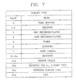
- Figure 7 is an explanatory view illustrating the code value and meaning of a subunit type identifying the type of the digital equipment according to the present invention.
- the code values (0 ⁇ 1F 16 ) of the subunit type are identified as Video Monitor, Reserved, Disc Recorder/Player, Tape Recorder/Player, Tuner, Reserved, Video camera, Reserved, Vendor Unique, Reserved for all Subunit Types, Extended Subunit Type, and Unit, respectively.
- Figure 8 is a flow chart illustrating a method for generating a command frame and/or a response frame transmitted/received through the digital interface according to the present invention.
- the host processor(main processor) 220 generates a digital equipment code and operation control signal upon receipt of a signal outputted from the input unit for thereby transmitting S10 the same to the frame processor 230.
- the search unit 231 of the frame processor 230 receives S11 the digital equipment code and operation control signal, and searches S12 for the code value corresponding to the digital equipment code in the internal memory 234 inside the frame processor, thus determining the type of the corresponding a digital equipment.
- the extra flash memory is searched S17 for the corresponding code value, thereby determining the type of the digital equipment.
- the flash memory 240 can store data in addition to the code values related to the digital equipment later.
- the internal memory 234 of the frame processor or the flash memory 240 detects the code value of the corresponding command and/or response frame.
- the detected code value is generated S15 in the command and response frame generation unit in the form appropriate for the corresponding a digital equipment, and is transmitted to the host processor(main processor) 220 or the IEEE 1394 processor 250.
- the command and/or response frame is processed so as to be transmitted from the IEEE 1394 processor 250 to the IEEE 1394 cable, and then is transmitted and received to/from other digital equipment through the asynchronous channel of the IEEE 1394.
Landscapes
- Engineering & Computer Science (AREA)
- Multimedia (AREA)
- Signal Processing (AREA)
- Computer Networks & Wireless Communication (AREA)
- General Engineering & Computer Science (AREA)
- Theoretical Computer Science (AREA)
- Physics & Mathematics (AREA)
- General Physics & Mathematics (AREA)
- Human Computer Interaction (AREA)
- Communication Control (AREA)
- Information Transfer Systems (AREA)
- Signal Processing For Digital Recording And Reproducing (AREA)
- Small-Scale Networks (AREA)
- Two-Way Televisions, Distribution Of Moving Picture Or The Like (AREA)
- Selective Calling Equipment (AREA)
Abstract
Description
- The present invention relates to an apparatus and method for generating a command frame and/or a response frame transmitted and received to/from a digital equipment connected to a digital interface, and more particularly, to an apparatus and method for generating a command frame and/or a response frame for the control of a digital equipment which is capable of easily generating a command frame and/or a response frame of a size appropriate for the digital equipment.
- Generally, a command frame and/or response frame transmitted and received to/from a digital equipment connected to a digital interface is generated in the form appropriate for the type of a digital equipment by searching command and/or response frame identification codes stored by means of a control signal according to the type of the digital equipment inputted by an user. The generated command and/or response frame is transmitted to the corresponding a digital equipment.
- Figure 1 is a block diagram illustrating a digital equipment connected to a digital interface according to the conventional art, wherein a variety of a digital equipment such as a digital VCR(D-VCR or D-VHS) 100, digital television(D-TV) 110, digital audio(D-Audio) 120, DVD(Digital Versatile Disc) recorder/
reproducer 130 is connected to the above-said digital interface. Here, the IEEE1 394 is used as the digital interface. - Figure 2 is a block diagram of parts of a digital VCR(D-VCR or D-VHS) 100 and digital television(D-TV) 110 connected to a digital interface according to the conventional art.
- The above-said
digital VCR 100 includes: adigital VCR processor 101 for receiving a signal inputted from the outside to process the same; a digital VCR program( D-VCR program) 102 constructed inside thedigital VCR processor 101; aframe processing program 103 constructed inside thedigital VCR program 102 for storing command and response frame formats according to the type of a digital equipment; and a digital interface processor (IEEE 1394 processor) 104 for generating the command and response frames appropriate for the digital equipment generated from thedigital VCR processor 101 so as to be transmitted and received to/from a digital interface. - The above digital television(D-TV) 110 is constructed in the same manner as the above-described
digital VCR 100. - The thusly constructed method for generating a command frame and response frame according to the conventional art will be described in detail.
- When a signal for interfacing with the
digital television 110 is inputted to thedigital VCR 100, the inputted signal is transmitted to the digital VCR processor(D-VCR processor) 101. Thedigital VCR processor 101 determines the command and/or response frame appropriate for the type of a corresponding a digital equipment, among command and/or response frames according to the type of a digital equipment pre-stored in aframe processing program 103 of the D-VCR program 102 by means of the above inputted signal. The determined command and/or response frame is transmitted to the IEEE 1394processor 104 to thus be generated in the form appropriate for the transmission to thedigital television 110, and the generated command and/or response frame is transmitted through an asynchronous channel of the IEEE 1394. Meanwhile, generated or received video/data data is transmitted through an isochronous channel of the IEEE 1394. - In addition, the transmitted command and/or response frame is received from the IEEE 1394
processor 114 of thedigital television 110. Adigital TV processor 111 corresponding to thedigital VCR processor 101 generate a command frame and/or a response frame in the same method as the above-described method for generating a command frame and/or a response frame for thedigital VCR 100 to thus transmit the same to the asynchronous channel of the IEEE 1394, and the generated or received video/audio data is transmitted through the isochronous channel of the IEEE 1394. - However, the command and/or response frame transmitted/received through the asynchronous channel is previously standardized according to the type of a digital equipment. Therefore, the method for generating a command frame and/or a response frame according to the conventional art has a problem that each of the command frame and response frame related to the type of a digital equipment connected to a digital interface must be repeatedly programmed.
- Accordingly, it is an object of the present invention to provide an apparatus and method for generating a command frame and/or a response frame transmitted and received to/from a digital equipment.
- The present invention will become better understood with reference to the accompanying drawings which are given only by way of illustration and thus are not limitative of the present invention, wherein:
- Figure 1 is a block diagram illustrating a digital equipment connected to a digital interface according to the conventional art;
- Figure 2 is a block diagram of parts of a digital VCR(D-VCR or D-VHS) and digital television(D-TV) connected to a digital interface according to the conventional art;
- Figure 3 is a block diagram illustrating an apparatus for generating a command frame and/or a response frame transmitted/received through a digital interface according to the present invention;
- Figure 4 is a detailed block diagram illustrating parts of the apparatus for generating a command frame and/or a response frame transmitted/received through the digital interface according to the present invention;
- Figures 5A and 5B are explanatory views of a command frame format for transmitting/receiving through the digital interface according to the present invention;
- Figures 6A and 6B are explanatory views of a response frame format transmitted/received through the digital interface according to the present invention;
- Figure 7 is an explanatory view illustrating the code value and meaning of a subunit type identifying the type of the digital equipment according to the present invention; and
- Figure 8 is a flow chart illustrating a method for generating a command frame and/or a response frame transmitted/received through the digital interface according to the present invention.
-
- The preferred embodiment of the present invention will now be described with reference to the accompanying drawings.
- Figure 3 is a block diagram illustrating an apparatus for generating a command frame and/or a response frame transmitted/received through a digital interface according to the present invention.
- The apparatus includes: an input unit such as a
keyboard 200 or remote control (R/C) 210 having a plurality of operation buttons; a host processor(main processor) 220 for outputting a digital equipment code and operation control signal upon receipt of a signal outputted from the input unit; aframe processor 230 for determining the type of a digital equipment and generating a command frame and response frame corresponding to the digital equipment upon receipt of the digital equipment code and operation control signal; adigital interface processor 250 for receiving the command frame and response frame and processing the same so as to be transmitted to the digital equipment connected to the digital interface; and aflash memory 240 for storing information on the format of the type of a digital equipment besides an internal memory of theframe processor 230. - The operation of the thusly constructed apparatus of the present invention will be explained by taking the IEEE 1394 as an example.
- First, when an user inputs a signal for interfacing with a certain particular to the input unit, a host processor(main processor) 220 receives the inputted signal from the outside, and outputs a digital equipment code and operation control signal to the
frame processor 230. - The
frame processor 230 determines the type of a digital equipment by means of an identification value recorded in the field of subunit type to be described in Figure 7, which corresponding to the received code value of the digital equipment. - By the determined a digital equipment, a command frame and/or a response frame corresponding to the type of the corresponding a digital equipment is determined by searching command and/or response frames pre-stored in the memory, and is transmitted to the host processor(main processor) 220. The command and/or response frame inputted to the host processor(main processor) 220 is outputted to the IEEE 1394
processor 250, and the outputted command and/or response framed is processed in such a manner that it is transmitted to the IEEE 1394, and is transmitted and received to/from an asynchronous channel of the IEEE 1394. - Meanwhile, the video/audio data reproduced or received from the host processor(main processor) 220 is transmitted and received through an isochronous channel of the IEEE 1394.
- At this time, the command and/or response frame generated from the
frame processor 230 can be directly transmitted to the IEEE 1394processor 250. - Figure 4 is a detailed block diagram illustrating parts of the apparatus for generating a command frame and/or a response frame transmitted/received through the digital interface according to the present invention.
- The
frame processor 230 includes: asearch unit 231 for searching for a certain particular code value stored in relation to the type of a digital equipment corresponding to a digital equipment code and operation control signal inputted from the host processor(main processor) 220; a storing unit for storing the code value of a command frame and/or a response frame; a commandframe generation unit 232 for generating a command frame using the searched code value; and a responseframe generation unit 233 for generating a response frame using the searched code value. - The storing unit includes an
internal storing unit 234 of theframe processor 230 and anextra flash memory 240. At this time, even if there is nointernal storing unit 234 of theframe processor 230 in the storing unit, it is possible to perform the same operation as that of theinternal storing unit 234 by means of theextra flash memory 240 alone. - The above-described method for generating a command frame and/or a response frame according to the present invention will now be described in detail.
- When a digital equipment code value and operation control signal is inputted from the host processor(main processor) 220, the
search unit 231 determines the type of a digital equipment corresponding to the inputted code of the digital equipment from an identification value recorded in the field of subunit type stored in the storing unit, and detects the code value of the command and/or response frame corresponding to the determined type of the digital equipment among command and/or response frames stored in the storing unit. - The detected code value of the command frame is transmitted to the command
frame generation unit 232 to thus be generated in the form appropriate for the digital equipment connected to the digital interface. The detected code value of the response frame is also transmitted to the responseframe generation unit 233 to thus be generated in the form appropriate for the digital equipment connected to the digital interface, in the same manner as the above-described method for generating a command frame. - The generated command and/or response frame is transmitted to the host processor(main processor) 220, or the IEEE 1394
processor 250 to thus be transmitted and received to/from other digital equipment through an IEEE 1394 cable. - Figures 5A and 5B is an explanatory view of a command frame format for transmitting/receiving through the digital interface according to the present invention.
- Figure 5A illustrates a command frame format, which includes: a command type field for identifying a command frame; a subunit type field and subunit ID field for identifying the type of a digital equipment; an operation code (Opcode) field; a plurality of operand fields; and a padding region in which, if necessary, unnecessary data (Null = '0') is padded.
- Figure 5B illustrates code values (0∼7) recorded in the command type field, which are identified as Control, Status, Specific Inquiry, Notify, General Inquiry, and Reserved, respectively.
- Figure 6A and 6B are explanatory views of a response frame format transmitted/received through the digital interface according to the present invention.
- Figure 6A illustrates a response frame format, which includes: a response type field for identifying a response frame; a subunit type field and subunit ID field for identifying the type of a digital equipment; an operation code (Opcode) field; a plurality of operand fields; and a padding region in which, if necessary, unnecessary data (Null = '0') is padded.
- Figure 6B illustrates code values (8∼F16) recorded in the response type field, which are identified as Not Implemented, Accepted, Rejected, Intransition, Implemented/Stable, Changed, Reserved, and Interim, respectively.
- Figure 7 is an explanatory view illustrating the code value and meaning of a subunit type identifying the type of the digital equipment according to the present invention.
- The code values (0∼1F16) of the subunit type are identified as Video Monitor, Reserved, Disc Recorder/Player, Tape Recorder/Player, Tuner, Reserved, Video camera, Reserved, Vendor Unique, Reserved for all Subunit Types, Extended Subunit Type, and Unit, respectively.
- Figure 8 is a flow chart illustrating a method for generating a command frame and/or a response frame transmitted/received through the digital interface according to the present invention.
- The host processor(main processor) 220 generates a digital equipment code and operation control signal upon receipt of a signal outputted from the input unit for thereby transmitting S10 the same to the
frame processor 230. Thesearch unit 231 of theframe processor 230 receives S11 the digital equipment code and operation control signal, and searches S12 for the code value corresponding to the digital equipment code in theinternal memory 234 inside the frame processor, thus determining the type of the corresponding a digital equipment. - At this time, if the code value of the corresponding a digital equipment is not stored in the
internal memory 234 of the frame processor, the extra flash memory is searched S17 for the corresponding code value, thereby determining the type of the digital equipment. Theflash memory 240 can store data in addition to the code values related to the digital equipment later. - Afterwards, when the type of the digital equipment is determined S14 by the above operation, the
internal memory 234 of the frame processor or theflash memory 240 detects the code value of the corresponding command and/or response frame. - The detected code value is generated S15 in the command and response frame generation unit in the form appropriate for the corresponding a digital equipment, and is transmitted to the host processor(main processor) 220 or the
IEEE 1394processor 250. - Accordingly, the command and/or response frame is processed so as to be transmitted from the
IEEE 1394processor 250 to theIEEE 1394 cable, and then is transmitted and received to/from other digital equipment through the asynchronous channel of theIEEE 1394. - As described above, in the apparatus and method for easily generating a command frame and/or a response frame transmitted/received through the asynchronous channel of the digital interface according to the present invention, there is an effect that the digital equipment must not be repeatedly programmed in order to generate a command frame and/or a response frame as in the conventional art.
- As the present invention may be embodied in several forms without departing from the spirit or essential characteristics thereof, it should also be understood that the above-described embodiments are not limited by any of the details of the foregoing description, unless otherwise specified, but rather should be construed broadly within its spirit and scope as defined in the appended claims, and therefore all changes and modifications that fall within the meets and bounds of the claims, or equivalences of such meets and bounds are therefore intended to be embraced by the appended claims.
Claims (11)
- An apparatus for generating a command frame and/or a response frame for the control of a digital equipment, comprising:a host processor (220) for outputting a digital equipment code and operation control signal upon receipt of the signal inputted from the input unit (200, 210);a frame processor (230) for determining the type of the digital equipment upon receipt of the digital equipment code and operation control signal, and generating a command frame and/or a response frame; anda digital interface processor (250) for receiving the command and/or response frame and processing the same so as to be transmitted to the digital interface connecting the digital equipment.
- The apparatus of claim 1, wherein the frame processor (230) comprises:a search unit (231) for searching for a certain particular code value stored in relation to the type of a digital equipment corresponding to a digital equipment code and operation control signal outputted from the host processor (220);a storing unit for storing the code value of a command frame and/or a response frame;a command frame generation unit (232) for generating a command frame using the searched code value; anda response frame generation unit (233) for generating a response frame using the searched code value.
- The apparatus of claim 2, wherein the search unit (231) of the frame processor (230) determines the type of the digital equipment by searching for the code value corresponding to the digital equipment code transmitted from the host processor (220) in the storing unit, and detects the code value of the command frame and response framed corresponding to the determined a digital equipment for thereby providing the same to the frame generation unit (232, 233).
- The apparatus of claim 2, wherein the storing unit comprises an internal memory (234) of the frame processor (230) and an extra flash memory (240).
- The apparatus of claim 4, wherein the storing unit performs the same operation as that of the internal memory (234) by means of the extra flash memory (240) alone.
- The apparatus of claim 5, wherein the flash memory (240) additionally stores the code value of the command and/or response frame for the digital equipment later.
- A method for generating a command frame and/or a response frame for the control of a digital equipment, comprising the steps of:generating a digital equipment code and command control signal by means of a signal outputted from an input unit (200, 210);determining the type of the digital equipment corresponding to the digital equipment code, and the command and/or response frame corresponding to the digital equipment; andprocessing the determined command and/or response frame in an appropriate form so as to be transmitted to a digital interface.
- The method of claim 7, wherein the step of determining the type of the digital equipment is determined according to the identification value recorded in a subunit type value stored in a storing unit .
- The method of claim 7, wherein the command and/or response frame corresponding to the determined type of the digital equipment is determined by searching command and/or response frames stored in an internal memory (234) or flash memory (240).
- The method of claim 7, wherein the command and/or response frame is transmitted and received to/from an asynchronous channel of the digital interface.
- The method of claim 7, wherein the command and/or response frame can be indirectly transmitted to an IEEE 1394 processor (250) through a host processor (220), or can be directly transmitted to the IEEE 1394 processor (250).
Applications Claiming Priority (2)
| Application Number | Priority Date | Filing Date | Title |
|---|---|---|---|
| KR1019990040589A KR100620186B1 (en) | 1999-09-21 | 1999-09-21 | Apparatus and method for generating command and response frames in digital interface |
| KR4058999 | 1999-09-21 |
Publications (2)
| Publication Number | Publication Date |
|---|---|
| EP1087621A2 true EP1087621A2 (en) | 2001-03-28 |
| EP1087621A3 EP1087621A3 (en) | 2003-06-11 |
Family
ID=19612391
Family Applications (1)
| Application Number | Title | Priority Date | Filing Date |
|---|---|---|---|
| EP00402601A Withdrawn EP1087621A3 (en) | 1999-09-21 | 2000-09-20 | Apparatus and method for control of digital equipment |
Country Status (4)
| Country | Link |
|---|---|
| US (1) | US6715015B1 (en) |
| EP (1) | EP1087621A3 (en) |
| JP (1) | JP3884225B2 (en) |
| KR (1) | KR100620186B1 (en) |
Cited By (1)
| Publication number | Priority date | Publication date | Assignee | Title |
|---|---|---|---|---|
| EP1667458A1 (en) * | 2004-12-03 | 2006-06-07 | Sanyo Electric Co., Ltd. | AV equipment |
Families Citing this family (4)
| Publication number | Priority date | Publication date | Assignee | Title |
|---|---|---|---|---|
| KR100453961B1 (en) * | 2001-10-24 | 2004-10-20 | 엘지전자 주식회사 | Transmitting method of command/response frame in digital interface apparatus |
| WO2017145287A1 (en) * | 2016-02-24 | 2017-08-31 | 京セラ株式会社 | Management system and management method |
| CN112272063B (en) * | 2020-10-26 | 2022-06-03 | 哈尔滨诺信工大测控技术有限公司 | Simulator suitable for satellite equipment testing |
| KR102918539B1 (en) * | 2021-09-27 | 2026-01-26 | 삼성전자 주식회사 | Operating method of storage device and host, and storage system including storage device and host |
Citations (1)
| Publication number | Priority date | Publication date | Assignee | Title |
|---|---|---|---|---|
| DE334368C (en) * | 1918-09-22 | 1921-03-12 | Rudolf Wagner Dr | Firing for oil-fired water tube boilers |
Family Cites Families (12)
| Publication number | Priority date | Publication date | Assignee | Title |
|---|---|---|---|---|
| WO1990015394A1 (en) | 1989-06-02 | 1990-12-13 | Aisi Research Corporation | Appliance interface for exchanging data |
| KR940016216A (en) | 1992-12-28 | 1994-07-22 | 오오가 노리오 | Audio / Video System and Connection Settings |
| JPH08161236A (en) * | 1994-11-30 | 1996-06-21 | Nec Corp | Data backup system by flash memory |
| JP3586548B2 (en) | 1997-01-10 | 2004-11-10 | シャープ株式会社 | Communication method, communication system, computer-readable recording medium storing communication program, and communication device |
| JPH10254811A (en) * | 1997-03-12 | 1998-09-25 | Sony Corp | Electronic device control apparatus and method |
| KR100230281B1 (en) * | 1997-04-14 | 1999-11-15 | 윤종용 | Multi-media system for transmitting and receiving a program number and method for transmitting and receiving a program number |
| JP3249069B2 (en) | 1997-06-12 | 2002-01-21 | 矢崎総業株式会社 | Information network system and method for controlling functional devices of the system |
| JP3656874B2 (en) * | 1997-07-04 | 2005-06-08 | ソニー株式会社 | Electronic device control system and method, playback device, and output device |
| WO1999007114A1 (en) | 1997-08-04 | 1999-02-11 | Matsushita Electric Industrial Co., Ltd. | A network control system |
| US6349352B1 (en) | 1998-01-06 | 2002-02-19 | Sony Corporation Of Japan | Home audio/video network with both generic and parameterized device control |
| JPH11205363A (en) | 1998-01-20 | 1999-07-30 | Nec Corp | IEEE 1394 equipment control device |
| JPH11252093A (en) | 1998-02-27 | 1999-09-17 | Sony Corp | Information processing apparatus and method, and providing medium |
-
1999
- 1999-09-21 KR KR1019990040589A patent/KR100620186B1/en not_active Expired - Fee Related
-
2000
- 2000-09-19 US US09/664,770 patent/US6715015B1/en not_active Expired - Lifetime
- 2000-09-20 EP EP00402601A patent/EP1087621A3/en not_active Withdrawn
- 2000-09-21 JP JP2000287412A patent/JP3884225B2/en not_active Expired - Fee Related
Patent Citations (1)
| Publication number | Priority date | Publication date | Assignee | Title |
|---|---|---|---|---|
| DE334368C (en) * | 1918-09-22 | 1921-03-12 | Rudolf Wagner Dr | Firing for oil-fired water tube boilers |
Cited By (1)
| Publication number | Priority date | Publication date | Assignee | Title |
|---|---|---|---|---|
| EP1667458A1 (en) * | 2004-12-03 | 2006-06-07 | Sanyo Electric Co., Ltd. | AV equipment |
Also Published As
| Publication number | Publication date |
|---|---|
| US6715015B1 (en) | 2004-03-30 |
| EP1087621A3 (en) | 2003-06-11 |
| KR100620186B1 (en) | 2006-09-01 |
| KR20010028380A (en) | 2001-04-06 |
| JP2001156879A (en) | 2001-06-08 |
| JP3884225B2 (en) | 2007-02-21 |
Similar Documents
| Publication | Publication Date | Title |
|---|---|---|
| US7162145B2 (en) | Multimedia system for transferring and receiving program number and methods therefor | |
| CN100594717C (en) | Display device and method for marking audio and video signal input sources | |
| US6219839B1 (en) | On-screen electronic resources guide | |
| US6430743B1 (en) | Apparatus of storing URL transmitted via vertical blanking interval of television signal | |
| US6366731B1 (en) | Digital broadcast receiving/recording apparatus and method | |
| US8365223B2 (en) | Device control processing apparatus and method, display processing apparatus and method, and computer program | |
| US20040097246A1 (en) | Methods and apparatus for displaying textual data embedded in broadcast media signals | |
| US20080297371A1 (en) | Electronic apparatus and connected apparatus searching method | |
| KR100821420B1 (en) | Signal output device and signal output method | |
| US8095709B2 (en) | Device name editing apparatus and device name display method | |
| US20050076310A1 (en) | Display controller, display control method, and recording medium with program for executing the display control method recorded therein | |
| US6715015B1 (en) | Apparatus and method for generating command and/or response frame for control of digital equipment | |
| JP2003018495A (en) | Digital broadcast receiving apparatus and digital broadcast receiving method | |
| US7499107B2 (en) | Method and apparatus for controlling an external device by remapping keys on a user input device | |
| US7015974B2 (en) | OSD (on screen display) object display method and apparatus | |
| US7508378B2 (en) | Remote control system, remote control operating device, and remote control method | |
| US7095447B2 (en) | OSD (on screen display) cursor display method and cursor image display apparatus | |
| JP2002538686A (en) | Blocking system | |
| JP3003584B2 (en) | TV / video control device | |
| US20070212020A1 (en) | Timer reservation device and information recording apparatus | |
| US20010046231A1 (en) | Communication control apparatus | |
| JP4646791B2 (en) | Digital content receiving apparatus and display method | |
| US20050134690A1 (en) | Control apparatus, video processing apparatus, and control method thereof | |
| JP3360467B2 (en) | Recording device | |
| US20020010752A1 (en) | Information processing apparatus, method thereof, information processing system, and medium |
Legal Events
| Date | Code | Title | Description |
|---|---|---|---|
| PUAI | Public reference made under article 153(3) epc to a published international application that has entered the european phase |
Free format text: ORIGINAL CODE: 0009012 |
|
| AK | Designated contracting states |
Kind code of ref document: A2 Designated state(s): AT BE CH CY DE DK ES FI FR GB GR IE IT LI LU MC NL PT SE |
|
| AX | Request for extension of the european patent |
Free format text: AL;LT;LV;MK;RO;SI |
|
| PUAL | Search report despatched |
Free format text: ORIGINAL CODE: 0009013 |
|
| AK | Designated contracting states |
Designated state(s): AT BE CH CY DE DK ES FI FR GB GR IE IT LI LU MC NL PT SE |
|
| AX | Request for extension of the european patent |
Extension state: AL LT LV MK RO SI |
|
| RIC1 | Information provided on ipc code assigned before grant |
Ipc: 7H 04B 1/20 B Ipc: 7H 04L 12/28 B Ipc: 7H 04N 5/00 B Ipc: 7H 04B 1/00 B Ipc: 7H 04N 7/24 A |
|
| 17P | Request for examination filed |
Effective date: 20030808 |
|
| AKX | Designation fees paid |
Designated state(s): DE FR GB |
|
| 17Q | First examination report despatched |
Effective date: 20041118 |
|
| 17Q | First examination report despatched |
Effective date: 20041118 |
|
| STAA | Information on the status of an ep patent application or granted ep patent |
Free format text: STATUS: THE APPLICATION HAS BEEN WITHDRAWN |
|
| 18W | Application withdrawn |
Effective date: 20080930 |