EP1087558A2 - Methods and apparatus for adaptive mimic rejection - Google Patents
Methods and apparatus for adaptive mimic rejection Download PDFInfo
- Publication number
- EP1087558A2 EP1087558A2 EP00308092A EP00308092A EP1087558A2 EP 1087558 A2 EP1087558 A2 EP 1087558A2 EP 00308092 A EP00308092 A EP 00308092A EP 00308092 A EP00308092 A EP 00308092A EP 1087558 A2 EP1087558 A2 EP 1087558A2
- Authority
- EP
- European Patent Office
- Prior art keywords
- bit position
- framing
- identified
- threshold value
- pattern
- Prior art date
- Legal status (The legal status is an assumption and is not a legal conclusion. Google has not performed a legal analysis and makes no representation as to the accuracy of the status listed.)
- Granted
Links
- 238000000034 method Methods 0.000 title claims abstract description 27
- 230000003278 mimic effect Effects 0.000 title abstract description 44
- 230000003044 adaptive effect Effects 0.000 title description 7
- 238000009432 framing Methods 0.000 claims abstract description 133
- 230000005540 biological transmission Effects 0.000 claims abstract description 25
- 238000012545 processing Methods 0.000 claims description 3
- 238000001514 detection method Methods 0.000 description 30
- 238000010586 diagram Methods 0.000 description 6
- 230000003247 decreasing effect Effects 0.000 description 2
- 230000006978 adaptation Effects 0.000 description 1
- 230000000694 effects Effects 0.000 description 1
- 230000008030 elimination Effects 0.000 description 1
- 238000003379 elimination reaction Methods 0.000 description 1
- 238000012423 maintenance Methods 0.000 description 1
- 238000012986 modification Methods 0.000 description 1
- 230000004048 modification Effects 0.000 description 1
- 230000011664 signaling Effects 0.000 description 1
Images
Classifications
-
- H—ELECTRICITY
- H04—ELECTRIC COMMUNICATION TECHNIQUE
- H04L—TRANSMISSION OF DIGITAL INFORMATION, e.g. TELEGRAPHIC COMMUNICATION
- H04L7/00—Arrangements for synchronising receiver with transmitter
- H04L7/04—Speed or phase control by synchronisation signals
- H04L7/08—Speed or phase control by synchronisation signals the synchronisation signals recurring cyclically
-
- H—ELECTRICITY
- H04—ELECTRIC COMMUNICATION TECHNIQUE
- H04J—MULTIPLEX COMMUNICATION
- H04J3/00—Time-division multiplex systems
- H04J3/02—Details
- H04J3/06—Synchronising arrangements
- H04J3/0602—Systems characterised by the synchronising information used
- H04J3/0605—Special codes used as synchronising signal
- H04J3/0608—Detectors therefor, e.g. correlators, state machines
Definitions
- the invention relates generally to data transmission systems and, more particularly, to data transmission systems employing frame alignment techniques.
- Modern telecommunication systems transmit large amounts of data rapidly between data communications devices.
- the receiving equipment In digital data transmission systems, the receiving equipment must be able to discern where in the bit stream being received from the transmitting equipment one distinct package, i.e., frame, of information ends and where the next frame begins. This is known as frame alignment.
- Frame alignment is performed both for a new transmission as well as an existing transmission where frame alignment is lost during the course of the transmission.
- a T1 system uses a 1.544 megabits/second pulse code modulation (PCM) digital signal.
- the T1 signal includes 24 time domain multiplexed channels, for carrying 24 separate channels, such as voice conversations, simultaneously on the single T1 carrier.
- eight bits comprise a single sample composed of one 7-bit A/D sample of one voice channel plus one signaling bit.
- a "frame" is defined as 24 samples, plus one framing bit termed the F bit which occupies the first bit position, for 193 total bits per frame.
- a superframe is defined as 12 frames. Each channel is sampled at an 8 KHz rate, so the T1 signal comprises 8000 193-bit frames per second, or 1.544 megabits/second.
- a frame alignment unit i.e., frame aligner
- a data receiver searches the incoming bit stream for a framing detection pattern.
- the frame aligner identifies the framing pattern, the unit declares a frame alignment condition.
- a conventional frame aligner In order to prevent framing onto a false framing pattern, a conventional frame aligner only declares frame alignment when there are no false framing patterns present. This is because the conventional frame alignment algorithm employed by a frame aligner is not capable of discerning the difference between a false framing pattern and the true framing pattern. Thus, conventional frame alignment units wait until the false framing patterns go away and there is only one frame detection candidate left. The remaining candidate is then chosen as the frame alignment position. During the wait, new false framing patterns may appear and these must also go away before a frame alignment position can be chosen. In a conventional frame alignment algorithm, the minimum false framing pattern length, i.e., false framing pattern threshold, is fixed.
- the present invention provides methods and apparatus for improving frame alignment in a data transmission system.
- the invention provides an adaptive false framing pattern rejection methodology for implementation in a frame alignment unit of a data transmission system receiver.
- the phrase "false framing pattern" may hereinafter also be referred to as a "mimic.”
- the adaptive mimic rejection algorithm of the invention significantly speeds up the frame alignment process, particularly with respect to signals which contain a relatively large number of mimics.
- a method for use in aligning frames in a receiver of a data transmission system includes checking one or more bit positions associated with a received data stream to determine a number of bits in the bit positions, respectively, that match a predetermined bit pattern.
- the number for a bit position is compared to a first threshold value and a second threshold value.
- a bit position is identified as being associated with a false framing pattern or mimic when the number is not less than the first threshold value.
- a bit position is identified as a potential framing bit position or possible framing bit position when the number is not less than the second threshold value.
- the first threshold value is changed when a bit position is identified as a potential framing bit position and another bit position is identified as being associated with a false framing pattern.
- the first threshold value may be increased by a given value for every frame that a bit position is identified as a potential framing bit position and another bit position is identified as being associated with a false framing pattern.
- the given value may be a value of one, a value less than one, or a value greater than one.
- Frame alignment is declared when a bit position is identified as a potential framing bit position and no other bit position is identified as being associated with a false framing pattern.
- the time required to declare frame alignment is significantly decreased, especially in a false framing pattern-rich signal.
- a receiver employing the inventive frame alignment process with adaptive mimic rejection realizes increased data throughput. While the invention is particularly suitable to a T1 data transmission system, the invention is not so limited.
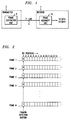
- the system includes a transmitter 2 coupled to a receiver 4 via a T1 line 6.
- the transmitter 2 includes a frame generation unit 8 which specifies the frame format of the data stream to be transmitted and sets the frame detection pattern that is to be used by the receiver 4 to align the received data stream.
- the receiver 4 includes a frame alignment unit 10 which aligns or synchronizes the received data stream so that the frames of data may be accurately decoded and/or processed by other circuits of the receiver.
- the frame alignment procedure of the invention is preferably employed in accordance with the frame alignment unit 10 of the receiver.
- a particular bit pattern e.g., 0010 Vietnamese
- This bit pattern is referred to as a frame detection pattern.
- the frame detection pattern is thus a sequence of frame bits specified for each particular type of frame format used in a data transmission system.
- consecutive bits of the framing detection pattern e.g., 0010 Vietnamese
- the framing bit positions e.g., bit position 1, of consecutive frames, e.g., frames 1 through N.
- the receiver 4 Since the receiver 4 does not necessarily know what frame or what bit position the data stream it has received starts at, it relies on the frame alignment unit 10 to make this determination and declare frame alignment.
- the frame alignment unit does this by locating the framing detection pattern in the received data stream and thus identifying the framing bit position. Given knowledge of the framing bit position and the framing detection pattern, the receiver knows the bit position and frame at which the data stream it has received starts.
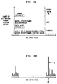
- FIGs. 3A and 3B graphical representations are shown illustrating the concept of framing and mimic thresholds for use in a frame alignment unit formed according to the present invention.
- a framing threshold FT
- Each bit position in a frame is a "candidate" for the framing bit position. This is because the frame alignment unit does not know which bit position in the data stream is the framing bit position.
- each bit position is checked once a frame to determine if it contains a bit value that is consistent with the frame detection pattern.
- the procedure includes checking each of the first 193 bit positions in the received data stream and each respective 193 rd bit thereafter to see which bit position contains the framing detection pattern.
- a framing detection pattern may contain 72 bits. Therefore, the full framing detection pattern would be evident by identifying the framing bit position over the 72 consecutive frames in which the pattern is present.
- a check of each bit position results in either incrementing the number of frame detection pattern bits matched (i.e., vertical axis of FIG. 3A) or dropping the number of frame detection pattern bits matched to a lower number.
- the lower number may represent the largest match from the beginning of the frame detection pattern up to the current bit. For example, assume in a simple example that the framing detection pattern is 12 bits, e.g., 100011011100, and a particular bit position matches the first seven bits of the pattern, 1000110. If the next value in that bit position was a zero, when a one was expected, then the number of frame detection bits matched would drop back to three, 100. However, if the value was a one, the number of frame detection bits matched would increase to eight, 10001101.
- the methodology of the invention provides for dropping back to the largest match possible that includes the beginning of the framing detection pattern and the bit just checked.
- the eighth bit received in the bit position under consideration was a zero and the sixth and seventh bits previously received were a one and a zero, respectively, resulting in a 100 being received. Since a 100 only matches the first three bits of the 12 bit framing detection pattern, the number of bits matched drops to three.
- a candidate that matches the frame detection pattern for the framing threshold number of bits (FT) is called a "possible framing bit," that is, a potential framing bit.
- a “mimic” is a candidate that has passed a threshold number of bits of the frame detection pattern, i.e., mimic threshold ⁇ . As illustrated in FIG. 3A, the mimic threshold is less than the framing threshold.
- the bit position referred to as FB is found to be the framing bit position since it is the only bit position that resulted in a pattern bit match number above the framing threshold FT.
- a possible framing bit is checked to see if it continues to match the framing pattern sequence and a check is done to see if there are any mimics or other possible framing bits. If the possible framing bit does not continue to match the framing pattern sequence, the bit position then becomes a candidate. If the possible framing pattern does continue to match the framing pattern sequence and there are no mimics or other possible framing bits, this bit position becomes the framing bit position and frame alignment is declared. However, if there are mimics or other possible framing bits, the bit position remains a possible framing bit.
- the frame alignment process adds a value ⁇ to the initial mimic threshold ⁇ for each frame that the first possible framing bit is waiting for all the mimics to go away, i.e., fall below the mimic threshold. It is to be appreciated that this effectively increases the mimic threshold, making it harder for a candidate to become a mimic.
- ⁇ is a positive number.
- a ⁇ value of 1 increases the mimic threshold by 1 bit each frame and thus prevents any new mimics from forming. That is, since the mimic threshold is being increased by one and you are only considering one more bit per frame, the number of frame detection pattern bits matched will not go above the adapted mimic threshold.
- a ⁇ value of less than 1 gradually increases the mimic threshold while allowing new mimics to form.
- a ⁇ value greater than 1 increases the mimic threshold more rapidly and removes the shortest mimics first while preventing new mimics from forming.
- the mimic threshold reaches the framing threshold (FT).
- the mimic threshold stops advancing and there are only possible framing bits remaining that are preventing frame alignment.
- the procedure includes selecting the possible framing bit that has been above the framing threshold FT the longest as the framing bit. Given identification of the framing bit and the framing detection threshold, the frame alignment unit declares frame alignment.
- the adaptation of the mimic threshold according to the invention may be represented by the following equation: M > ⁇ + ⁇ W where M is the current bit length of the mimic, ⁇ is the threshold bit length (minimum bit length of a mimic), ⁇ is the bit length increment and W is the number of frames since a possible framing bit has been found.
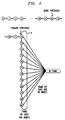
- each state of the state machine is represented by a circle with a state number in it.
- each state represents a bit position in a consecutive frame.
- incoming data bits are compared against a pattern. If the data bit matches the pattern bit required by its current state, the state machine can advance a state. Otherwise, it drops back to an initial state (state 0).
- the state number indicates how many pattern bits have matched. For the example shown, the mimic threshold is set at 12 frame pattern bit matches and the framing threshold FT is set at 72 frame pattern bit matches.
- the state machine rotates through a set of states in which the superframe alignment is maintained as long as the frame pattern continues to match. This is represented by the loop denoted by the letter A which includes states 72 through 83. Once all the mimics fail a pattern match, the state machine may advance from the maintenance states, i.e., loop A, to the frame alignment state. In order to hasten the elimination of mimics, as explained above, an offset ⁇ is added to the mimic threshold for every frame time after the framing threshold is reached.
- the states in the loop allow the state machine to identify the exact frame within the multi-frame framing format.
- the number of states in the loop is determined by the minimum number of frames within which the frame bit sequence repeats. For example, in the T1 superframe format, the frame bit sequence repeats every 12 frames. Hence, the 12-state loop as illustrated in FIG. 4.
- the T1 extended superframe format would use a 24 state loop.
- the number of states is not always equal to the number of frames that describe the framing format, that is, for example, the loop may be longer.
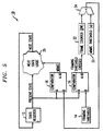
- FIG. 5 a schematic diagram illustrating a frame alignment circuit employing adaptive mimic rejection according to one embodiment of the present invention is shown. Similar to FIG. 4, the circuit diagram of FIG. 5 is based on states where a state is effectively a frame. Accordingly, the bit position in a particular frame, i.e., the present state, is considered. That is, its value is latched in a state register 12 and checked to see if it matches the frame detection pattern. If it does, the bits matched number (i.e., vertical axis of FIG. 3A) is increased, if not, it is decreased or at least is not increased.
- the bit matched number i.e., vertical axis of FIG. 3A
- the bits matched number is compared to the framing threshold (FT) 14 in a comparator 16 and to the mimic threshold in a comparator 18. If a possible framing bit has already been identified, the mimic threshold 20 is adapted for each frame that a mimic is still present. This is accomplished with frame counter 22 which keeps track of the number of frames. Thus, adder 24 adds the mimic threshold ⁇ and the value represented by ⁇ W . For example, ⁇ may be one. The sum is the new mimic threshold used by the comparator 18. If the result of the comparison is that a mimic still exists, i.e., a bit position has a bits matched number above the mimic threshold but below the framing threshold, the process continues onto the next state or frame. The value of the mimic threshold is increased by one for each frame that a possible framing bit is identified and a mimic still exists. If no mimic exists and a possible framing bit has been identified, this bit is considered to be the framing bit and frame alignment is declared.
- FT framing threshold
- the invention in general, and, specifically, the elements of the circuit illustrated in FIG. 5, may be implemented in a variety of ways.
- the invention may be implemented via one or more processing devices such as, for example, discrete electronic logic, one or more application-specific integrated circuits, or one or more appropriately programmed processors with associated memory.
- processing devices such as, for example, discrete electronic logic, one or more application-specific integrated circuits, or one or more appropriately programmed processors with associated memory.
Landscapes
- Engineering & Computer Science (AREA)
- Computer Networks & Wireless Communication (AREA)
- Signal Processing (AREA)
- Synchronisation In Digital Transmission Systems (AREA)
- Detection And Prevention Of Errors In Transmission (AREA)
Abstract
Description
Claims (15)
- A method for use in aligning frames in a receiver of a data transmission system, the method comprising:checking a bit position associated with a received data stream to determine a number of bits in the bit position that match a predetermined bit pattern and comparing the number to a first threshold value and a second threshold value, wherein a bit position is identified as being associated with a false framing pattern when the number is not less than the first threshold value and identified as a potential framing bit position when the number is not less than the second threshold value; andchanging the first threshold value when a bit position is identified as a potential framing bit position and another bit position is identified as being associated with a false framing pattern.
- The method of claim 1, wherein the first threshold value is increased by a given value for every frame that a bit position is identified as a potential framing bit position and another bit position is identified as being associated with a false framing pattern.
- The method of claim 2, wherein the given value by which the first threshold value is increased is one of a value of one, a value less than one, and a value greater than one.
- The method of claim 1, further comprising the step of declaring a frame alignment condition when a bit position is identified as a potential framing bit position and no other bit position is identified as being associated with a false framing pattern.
- The method of claim 1, wherein the data stream is received from a T1 data transmission line.
- Apparatus for use in aligning frames in a receiver of a data transmission system, the apparatus comprising:at least one processing device operative to: (i) check a bit position associated with a received data stream to determine a number of bits in the bit position that match a predetermined bit pattern and compare the number to a first threshold value and a second threshold value, wherein a bit position is identified as being associated with a false framing pattern when the number is not less than the first threshold value and identified as a potential framing bit position when the number is not less than the second threshold value, and (ii) change the first threshold value when a bit position is identified as a potential framing bit position and another bit position is identified as being associated with a false framing pattern.
- The apparatus of claim 6, wherein the first threshold value is increased by a given value for every frame that a bit position is identified as a potential framing bit position and another bit position is identified as being associated with a false framing pattern.
- The apparatus of claim 7, wherein the given value by which the first threshold value is increased is one of a value of one, a value less than one, and a value greater than one.
- The apparatus of claim 6, wherein the processing device is further operative to declare a frame alignment condition when a bit position is identified as a potential framing bit position and no other bit position is identified as being associated with a false framing pattern.
- The apparatus of claim 6, wherein the data stream is received from a T1 data transmission line.
- A receiver of a data transmission system, comprising:frame alignment equipment operative to: (i) check a bit position associated with a received data stream to determine a number of bits in the bit position that match a predetermined bit pattern and compare the number to a first threshold value and a second threshold value, wherein a bit position is identified as being associated with a false framing pattern when the number is not less than the first threshold value and identified as a potential framing bit position when the number is not less than the second threshold value, and (ii) change the first threshold value when a bit position is identified as a potential framing bit position and another bit position is identified as being associated with a false framing pattern.
- The receiver of claim 11, wherein the first threshold value is increased by a given value for every frame that a bit position is identified as a potential framing bit position and another bit position is identified as being associated with a false framing pattern.
- The receiver of claim 12, wherein the given value by which the first threshold value is increased is one of a value of one, a value less than one, and a value greater than one.
- The receiver of claim 11, wherein the frame alignment equipment is further operative to declare a frame alignment condition when a bit position is identified as a potential framing bit position and no other bit position is identified as being associated with a false framing pattern.
- The receiver of claim 11, wherein the data stream is received from a T1 data transmission line.
Applications Claiming Priority (2)
| Application Number | Priority Date | Filing Date | Title |
|---|---|---|---|
| US406030 | 1995-03-17 | ||
| US09/406,030 US6839392B1 (en) | 1999-09-27 | 1999-09-27 | Methods and apparatus for adaptive mimic rejection |
Publications (3)
| Publication Number | Publication Date |
|---|---|
| EP1087558A2 true EP1087558A2 (en) | 2001-03-28 |
| EP1087558A3 EP1087558A3 (en) | 2004-05-26 |
| EP1087558B1 EP1087558B1 (en) | 2011-07-20 |
Family
ID=23606268
Family Applications (1)
| Application Number | Title | Priority Date | Filing Date |
|---|---|---|---|
| EP00308092A Expired - Lifetime EP1087558B1 (en) | 1999-09-27 | 2000-09-18 | Methods and apparatus for frame alignment using adaptive mimic rejection |
Country Status (5)
| Country | Link |
|---|---|
| US (1) | US6839392B1 (en) |
| EP (1) | EP1087558B1 (en) |
| JP (1) | JP3443394B2 (en) |
| KR (1) | KR100662973B1 (en) |
| CA (1) | CA2320540C (en) |
Families Citing this family (3)
| Publication number | Priority date | Publication date | Assignee | Title |
|---|---|---|---|---|
| US7764644B2 (en) * | 2006-10-27 | 2010-07-27 | Motorola, Inc. | Method and apparatus for reducing overhead for signaling |
| KR101008729B1 (en) * | 2010-08-03 | 2011-01-24 | (주)파워엔지니어링 | Raw material supply measuring device of boiler |
| US9413569B2 (en) * | 2012-09-28 | 2016-08-09 | Nxp B.V. | Adaptive detector threshold compensation in binary frame based communication systems |
Family Cites Families (12)
| Publication number | Priority date | Publication date | Assignee | Title |
|---|---|---|---|---|
| GB1280827A (en) | 1968-10-28 | 1972-07-05 | Post Office | Improvements relating to apparatus for synchronizing a clock with a received signal |
| US4316284A (en) | 1980-09-11 | 1982-02-16 | Bell Telephone Laboratories, Incorporated | Frame resynchronization circuit for digital receiver |
| US5056119A (en) | 1990-01-08 | 1991-10-08 | Sakalian Steve Y | Adaptive frame resynchronizer apparatus |
| GB9126505D0 (en) * | 1991-12-13 | 1992-02-12 | Plessey Telecomm | Telecommunications system and method |
| US5557614A (en) * | 1993-12-22 | 1996-09-17 | Vlsi Technology, Inc. | Method and apparatus for framing data in a digital transmission line |
| KR100311965B1 (en) * | 1994-03-07 | 2001-12-28 | 박종섭 | Device and method for detecting synchronous signal |
| US5680421A (en) | 1995-02-27 | 1997-10-21 | Oki Electric Industry Co., Ltd. | Frame synchronization apparatus |
| US5809093A (en) * | 1995-06-02 | 1998-09-15 | Dsc Communications Corporation | Apparatus and method of frame aligning information in a wireless telecommunications system |
| US5621773A (en) * | 1996-03-08 | 1997-04-15 | Lsi Logic Corporation | Method and apparatus for fast synchronization of T1 extended superframes |
| CA2214743C (en) * | 1996-09-20 | 2002-03-05 | Ntt Mobile Communications Network Inc. | A frame synchronization circuit and communications system |
| US6002728A (en) * | 1997-04-17 | 1999-12-14 | Itt Manufacturing Enterprises Inc. | Synchronization and tracking in a digital communication system |
| US6011807A (en) * | 1997-07-18 | 2000-01-04 | Innova Corporation | Method and apparatus for transmitting data in a high speed, multiplexed data communication system |
-
1999
- 1999-09-27 US US09/406,030 patent/US6839392B1/en not_active Expired - Lifetime
-
2000
- 2000-09-18 EP EP00308092A patent/EP1087558B1/en not_active Expired - Lifetime
- 2000-09-25 CA CA002320540A patent/CA2320540C/en not_active Expired - Fee Related
- 2000-09-26 KR KR1020000056448A patent/KR100662973B1/en not_active Expired - Fee Related
- 2000-09-27 JP JP2000293220A patent/JP3443394B2/en not_active Expired - Fee Related
Also Published As
| Publication number | Publication date |
|---|---|
| KR100662973B1 (en) | 2006-12-28 |
| EP1087558A3 (en) | 2004-05-26 |
| EP1087558B1 (en) | 2011-07-20 |
| US6839392B1 (en) | 2005-01-04 |
| KR20010050645A (en) | 2001-06-15 |
| CA2320540A1 (en) | 2001-03-27 |
| JP3443394B2 (en) | 2003-09-02 |
| JP2001144740A (en) | 2001-05-25 |
| CA2320540C (en) | 2003-12-30 |
Similar Documents
| Publication | Publication Date | Title |
|---|---|---|
| US5621773A (en) | Method and apparatus for fast synchronization of T1 extended superframes | |
| US5768301A (en) | Apparatus and method for detecting and correcting pair swap, and implementing a link integrity function in a packet-based data communications system | |
| CN1092877C (en) | A Method for Realizing Discontinuous Transmission in Mobile Phone System | |
| US5072449A (en) | Packet framing using cyclic redundancy checking | |
| US20020163936A1 (en) | Bit-level control for dynamic bandwidth allocation | |
| EP1237319A1 (en) | Methods and apparatus for efficient and accurate coarse timing synchronization in burst demodulators | |
| EP0188443A1 (en) | An interface circuit for interfacing between asynchronous data in start/stop format and synchronous data | |
| US4763339A (en) | Digital word synchronizing arrangement | |
| US7287176B2 (en) | Apparatus, method and storage medium for carrying out deskew among multiple lanes for use in division transmission of large-capacity data | |
| US5737369A (en) | Apparatus and method for recovering data in the presence of error transients | |
| US6839392B1 (en) | Methods and apparatus for adaptive mimic rejection | |
| EP0174182A2 (en) | Information transmission system in a local area network suitable for collision detection | |
| US20040117499A1 (en) | System and method for detection of delineation of data units for a communication element | |
| US6424628B1 (en) | Analyzing signals | |
| US20050058080A1 (en) | Methods and apparatus for measuring service disruption | |
| US6271698B1 (en) | Method and apparatus for correcting imperfectly equalized bipolar signals | |
| US4771421A (en) | Apparatus for receiving high-speed data in packet form | |
| US6707902B2 (en) | Method of resynchronizing data transfer between two modems connected by a dedicated line | |
| EP4507225A1 (en) | Method for receiving oam code block, and device | |
| JPS592417B2 (en) | Communication synchronization method | |
| HK40116120A (en) | Method for receiving oam code block, and device | |
| KR100306875B1 (en) | Method for detecting start point of data frame over sequence code | |
| JP2000134190A (en) | Data transmission device and data communication device | |
| KR20040026319A (en) | Apparatus and method for frame synchronization in receiving transmission system | |
| JPH10276162A (en) | Information transmission method |
Legal Events
| Date | Code | Title | Description |
|---|---|---|---|
| PUAI | Public reference made under article 153(3) epc to a published international application that has entered the european phase |
Free format text: ORIGINAL CODE: 0009012 |
|
| AK | Designated contracting states |
Kind code of ref document: A2 Designated state(s): AT BE CH CY DE DK ES FI FR GB GR IE IT LI LU MC NL PT SE |
|
| AX | Request for extension of the european patent |
Free format text: AL;LT;LV;MK;RO;SI |
|
| PUAL | Search report despatched |
Free format text: ORIGINAL CODE: 0009013 |
|
| AK | Designated contracting states |
Kind code of ref document: A3 Designated state(s): AT BE CH CY DE DK ES FI FR GB GR IE IT LI LU MC NL PT SE |
|
| AX | Request for extension of the european patent |
Extension state: AL LT LV MK RO SI |
|
| 17P | Request for examination filed |
Effective date: 20040827 |
|
| AKX | Designation fees paid |
Designated state(s): DE FR GB |
|
| 17Q | First examination report despatched |
Effective date: 20050111 |
|
| RAP3 | Party data changed (applicant data changed or rights of an application transferred) |
Owner name: LUCENT TECHNOLOGIES INC. |
|
| GRAP | Despatch of communication of intention to grant a patent |
Free format text: ORIGINAL CODE: EPIDOSNIGR1 |
|
| RTI1 | Title (correction) |
Free format text: METHODS AND APPARATUS FOR FRAME ALIGNMENT USING ADAPTIVE MIMIC REJECTION |
|
| GRAS | Grant fee paid |
Free format text: ORIGINAL CODE: EPIDOSNIGR3 |
|
| GRAA | (expected) grant |
Free format text: ORIGINAL CODE: 0009210 |
|
| RIN1 | Information on inventor provided before grant (corrected) |
Inventor name: BAGHERI, MEHRAN Inventor name: WITINSKI, RICHARD C. Inventor name: MITCHELL, JAIME TADEP |
|
| AK | Designated contracting states |
Kind code of ref document: B1 Designated state(s): DE FR GB |
|
| REG | Reference to a national code |
Ref country code: GB Ref legal event code: FG4D |
|
| REG | Reference to a national code |
Ref country code: DE Ref legal event code: R096 Ref document number: 60046227 Country of ref document: DE Effective date: 20110908 |
|
| PLBE | No opposition filed within time limit |
Free format text: ORIGINAL CODE: 0009261 |
|
| STAA | Information on the status of an ep patent application or granted ep patent |
Free format text: STATUS: NO OPPOSITION FILED WITHIN TIME LIMIT |
|
| 26N | No opposition filed |
Effective date: 20120423 |
|
| REG | Reference to a national code |
Ref country code: DE Ref legal event code: R097 Ref document number: 60046227 Country of ref document: DE Effective date: 20120423 |
|
| PGFP | Annual fee paid to national office [announced via postgrant information from national office to epo] |
Ref country code: FR Payment date: 20130910 Year of fee payment: 14 |
|
| PGFP | Annual fee paid to national office [announced via postgrant information from national office to epo] |
Ref country code: DE Payment date: 20140911 Year of fee payment: 15 |
|
| PGFP | Annual fee paid to national office [announced via postgrant information from national office to epo] |
Ref country code: GB Payment date: 20140917 Year of fee payment: 15 |
|
| REG | Reference to a national code |
Ref country code: FR Ref legal event code: ST Effective date: 20150529 |
|
| PG25 | Lapsed in a contracting state [announced via postgrant information from national office to epo] |
Ref country code: FR Free format text: LAPSE BECAUSE OF NON-PAYMENT OF DUE FEES Effective date: 20140930 |
|
| REG | Reference to a national code |
Ref country code: DE Ref legal event code: R119 Ref document number: 60046227 Country of ref document: DE |
|
| GBPC | Gb: european patent ceased through non-payment of renewal fee |
Effective date: 20150918 |
|
| PG25 | Lapsed in a contracting state [announced via postgrant information from national office to epo] |
Ref country code: DE Free format text: LAPSE BECAUSE OF NON-PAYMENT OF DUE FEES Effective date: 20160401 Ref country code: GB Free format text: LAPSE BECAUSE OF NON-PAYMENT OF DUE FEES Effective date: 20150918 |
|
| REG | Reference to a national code |
Ref country code: DE Ref legal event code: R082 Ref document number: 60046227 Country of ref document: DE Representative=s name: DILG, HAEUSLER, SCHINDELMANN PATENTANWALTSGESE, DE Ref country code: DE Ref legal event code: R082 Ref document number: 60046227 Country of ref document: DE Representative=s name: DILG HAEUSLER SCHINDELMANN PATENTANWALTSGESELL, DE Ref country code: DE Ref legal event code: R081 Ref document number: 60046227 Country of ref document: DE Owner name: AVAGO TECHNOLOGIES GENERAL IP (SINGAPORE) PTE., SG Free format text: FORMER OWNER: LUCENT TECHNOLOGIES, INC., MURRAY HILL, N.J., US |