EP1087523A2 - Digital graphic equalizer control system and method - Google Patents
Digital graphic equalizer control system and method Download PDFInfo
- Publication number
- EP1087523A2 EP1087523A2 EP00308246A EP00308246A EP1087523A2 EP 1087523 A2 EP1087523 A2 EP 1087523A2 EP 00308246 A EP00308246 A EP 00308246A EP 00308246 A EP00308246 A EP 00308246A EP 1087523 A2 EP1087523 A2 EP 1087523A2
- Authority
- EP
- European Patent Office
- Prior art keywords
- filter
- gain
- set forth
- graphic equalizer
- filters
- Prior art date
- Legal status (The legal status is an assumption and is not a legal conclusion. Google has not performed a legal analysis and makes no representation as to the accuracy of the status listed.)
- Granted
Links
- 238000000034 method Methods 0.000 title claims description 32
- 230000008859 change Effects 0.000 claims description 10
- 230000003247 decreasing effect Effects 0.000 claims description 6
- 230000004044 response Effects 0.000 claims description 6
- 230000008569 process Effects 0.000 description 8
- 238000010586 diagram Methods 0.000 description 7
- 230000005236 sound signal Effects 0.000 description 7
- 230000008901 benefit Effects 0.000 description 4
- 230000000694 effects Effects 0.000 description 3
- 230000006870 function Effects 0.000 description 3
- 238000012546 transfer Methods 0.000 description 3
- 230000003595 spectral effect Effects 0.000 description 2
- 230000004075 alteration Effects 0.000 description 1
- 230000007423 decrease Effects 0.000 description 1
- 238000013461 design Methods 0.000 description 1
- 230000008030 elimination Effects 0.000 description 1
- 238000003379 elimination reaction Methods 0.000 description 1
- 238000001914 filtration Methods 0.000 description 1
- 238000004519 manufacturing process Methods 0.000 description 1
- 230000005055 memory storage Effects 0.000 description 1
- 230000005012 migration Effects 0.000 description 1
- 238000013508 migration Methods 0.000 description 1
- 238000012986 modification Methods 0.000 description 1
- 230000004048 modification Effects 0.000 description 1
- 230000035772 mutation Effects 0.000 description 1
- 238000012545 processing Methods 0.000 description 1
- 238000006467 substitution reaction Methods 0.000 description 1
- 238000000844 transformation Methods 0.000 description 1
- 230000009466 transformation Effects 0.000 description 1
Images



Classifications
-
- H—ELECTRICITY
- H03—ELECTRONIC CIRCUITRY
- H03G—CONTROL OF AMPLIFICATION
- H03G5/00—Tone control or bandwidth control in amplifiers
- H03G5/005—Tone control or bandwidth control in amplifiers of digital signals
Definitions
- This invention is related in general to the field of digital audio signal processing. More particularly, the invention is related to a digital graphic equalizer control system and method.
- a graphic equalizer is a piece of audio equipment used to flatten the system spectral response in the audio signal band or produce other desirable effects.
- Current mid- to high performance audio systems typically include an analog graphic equalizer.
- analog systems produce excellent sound, there is a steady migration to digital systems.
- Digital systems are less costly to manufacture, are easy and flexible to modify, are programmable, and are portable. Further, the source of the audio signal is increasingly more likely to be digital than analog.
- a graphic equalizer is made up of a set of equalizing filters with fixed center frequencies and bandwidths. Usually these filters are designed to span the entire audio band. The user is provided the capability to adjust the gain of these filters to change the equalization characteristics of the audio system and thus the output sound.
- the invention provides a digital graphic equalizer comprising a predetermined number of equalizing bands each having a different center frequency, the center frequencies spanning a predetermined audio bandwidth. For each equalizing band a first set of filters is provided. The filters have a predetermined linear uniform spacing between the gain of successive filters.
- the invention also provides a method of digital graphic equalizer control including the steps of receiving a user-selected gain setting for an equalizing filter, and increasing or decreasing the filter gain in uniform steps on a linear scale towards the user-selected gain setting.
- the invention further provides a digital audio system including such a digital graphic equalizer.
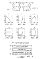
- FIGURE 1 is a block diagram of an audio system 10 having a digital graphic equalizer and a digital graphic equalizer controller constructed according to an embodiment of the present invention.
- Audio system 10 includes a sound source 12, which may be digital or analog. An analog sound source would require the use of an analog-to-digital converter (not shown) to convert the analog audio signal into a digital audio signal.
- the digital audio signal is provided to a digital graphic equalizer 14 which would be used to flatten the system frequency spectral response or to provide other desirable effects under the control of a controller or control system 16.
- Controller 16 may compute equalizing filter equations and may include memory (not shown) for storing equalizing filter settings and coefficients.
- the output from digital graphic equalizer 14 is provided to an audio amplifier 20, which adjusts the overall signal strength. Although not shown, it is understood that a digital-to-analog converter is required to convert the digital signal from digital tone control system 18 to analog.
- a speaker 22 receives the resultant analog audio signal from audio amplifier 20.
- FIGURE 2 is a graphic plot of an exemplary family of equalizing filters with representative gain increments for a 10-band graphic equalizer.
- the curves are plotted only in 6 dB gain increments for the sake of clarity.
- the typical increment is approximately 0.5 dB.
- the center frequencies of each band or channel are chosen, in this example, at the frequencies of the piano's C keys (32.7, 65.4, 130.8, 261.6, 523.3, 1046.5, 2093.0, and 4186.0 Hertz) with an additional 2 octaves above (8372.0, 16744.0 Hertz) to cover the entire audio band.
- the number of bands is chosen for suitability for a particular application.
- center frequencies may be 60, 250, 1,000, 4,000, 12,000 Hertz.
- the center frequencies may be easily modified.
- the center frequency/bandwidth value, or Q may be set at 2, 1.5 or 1.
- the family of curves shown in FIGURE 2 have a boost and cut range of +/- 18 dB, but may be less or greater than this example. Again, the range is easily programmable in a digital graphic equalizer.
- a digital graphic equalizer may have many different configurations.
- the number of bands or channels, the Qs, the sample rate, the adjustability range and granularity, the center frequencies, and other parameters may be chosen to suit the needs of a particular system design.
- FIGURE 3A is a graphic plot of an artifact-free family of equalizing filters for a single exemplary band constructed according to an embodiment of the present invention.
- the coefficients are changed such that the filter gains change in uniform steps on a linear plot according to the present invention.
- the equalizing filter is at a high gain setting, the gain is changed in very small and gradual increments to avoid generating audible artifacts. As the gain decreases, it becomes possible to change the gain in larger steps and yet still remain artifact free.
- FIGURE 3A shows a logarithmic plot which illustrates the exponential spacing between the gain settings of the family of equalizing filters.
- FIGURE 3B is a graphic plot of filter gain in dB versus dB spacing contrasting linearity in dB space and linearity in gain space.
- graphic equalizer controller 16 initializes each family of filters to a set of coefficients corresponding to one of the filters in the family, typically the 0 dB coefficients or the previous setting for the filter prior to system power down.
- graphic equalizer controller 16 automatically increments or decrements through all filters between the current setting and the final setting selected by the user.
- a predetermined number of minimum samples may be filtered with each set of coefficients. It has been shown that filtering approximately 64 samples for each set of coefficients with a sample rate of 44.1 KHz is satisfactory.
- FIGURE 4 is a graphic plot of an artifact-free full family of equalizing filters for a single band constructed according to an embodiment of the present invention. It may be seen in FIGURE 3A that the gain spacing for filters below 0 dB (the cut region) may be substantially greater than 0.5 dB and still remain artifact-free. However, this filter spacing is likely to provide an adjustable resolution that is too low for typical graphic equalizer applications. Most users desire an adjustable resolution less than 1 dB. Therefore, additional filters may be added to the cut region below 0 dB, as shown in FIGURE 4. In effect, the spacing in the cut region shown in FIGURE 4 is linear in dB space, with 0.5 dB increments.
- the family of filters shown in FIGURE 3A is the minimum set of filters derived by changing the coefficients to achieve identical spacing in gain space, and additional filters are added to the cut region below 0 dB to increase the granularity of gain adjustment, as shown in FIGURE 4.
- One way of adding the filters to the cut region is to provide filter gains that change in uniform 0.5 dB steps on a dB plot. Therefore, FIGURE 4 provides a preferred gain schedule for the family of filters in graphic equalizer 14. Although not specifically shown, similar gain schedule is used for each band in the graphic equalizer.
- FIGURE 5 a flowchart of an embodiment of graphic equalizer control method 40 according to the teachings of the present invention is shown.
- the filter coefficients are initialized to a default setting or a setting previously set.
- the user's gain selection or input is received by graphic equalizer controller 16.
- graphic equalizer controller 14 increments or decrements the filter gain by adjusting the filter coefficients according to the gain schedule such as the one shown in FIGURE 4.
- the filter coefficients are changed until the gain setting in the gain schedule closest to the user-selected gain is reached, as determined in block 48.
- the process ends in block 50.
- a relative gain increment is used to attain the user-selected gain.
- FIGURE 6 a graphic equalizer control method 60 using this technique is shown.
- the filter coefficients are initialized to a default setting or a setting previously set.
- the user's gain selection or input is received by graphic equalizer controller 16.
- a delta gain ( ⁇ gain) is computed by determining a difference between the user-selected gain and the current gain.
- the filter coefficients are adjusted so that the gain is incremented or decremented by the predetermined gain resolution value, as shown in blocks 66 and 68. This process is repeated until the user-selected gain is reached, as determined in block 72. Otherwise, the filter coefficients are adjusted so that the gain is incremented or decremented by delta gain to reach exactly the user-selected gain, as shown in block 70. The process ends in block 74.
- a predetermined gain resolution in gain (linear) space such as 0.055
- FIGURE 7 is a block diagram of a typical second order IIR filter which may be used to construct the equalizing filters of the present invention.
- the filter coefficients are a 0 , a 1 , a 2 , b 0 , b 1 , and b 2 and z -n is a delay of n samples.
- the coefficients for the entire family of filters and for all the bands are stored so that as the user changes the gain for a given filter, the coefficients can be quickly recalled and used to update the filters.
- storing all these coefficients is costly and memory intensive for many applications.
- FIGURES 8A-8F are graphic plots of the equalizing filter coefficients of the digital filter shown in FIGURE 7 according to an embodiment of the present invention.
- the coefficients are plotted against the filter index, where filter 1 is at 18 dB and filter 147 is at -18 dB. It may be seen that coefficient a 0 is always 1, coefficients b 1 and a 1 are identical, and the other coefficients appear to be readily obtainable by simple two-segment linearization approximation. Alternatively, piecewise linearization may be used.
- FIGURE 9 is a flowchart of an exemplary process 100 for obtaining the filter coefficients according to the teachings of the present invention.
- the process receives the index number of the filter for which the coefficients are required, as shown in block 102.
- Coefficient a 0 is set to a constant 1, as shown in block 104.
- the linearization approximation may be done by reading a stored set of coefficients, for example the coefficients for 0 dB, and the equations that approximate the coefficient plots.
- the process ends in block 110.
- FIGURE 10A is a block diagram of a filter 120 based on a second order allpass filter which may be used to construct the equalizing filters of the present invention.
- FIGURES 11A-11C are graphic plots of the filter coefficients of the allpass filter shown in FIGURE 10B according an embodiment of the present invention.
- the present invention teaches a new digital graphic equalizer that provides artifact-free sound as the gain settings are changed by the user. Furthermore, the invention provides for an efficient method for obtaining the filter coefficients best suited for those applications with limitations on memory storage, processor computational resources, physical size of the component, and other cost considerations.
Landscapes
- Tone Control, Compression And Expansion, Limiting Amplitude (AREA)
- Circuit For Audible Band Transducer (AREA)
Abstract
Description
Claims (24)
- A digital graphic equalizer system, comprising:a predetermined number of equalizing bands each having a different center frequency, the center frequencies spanning a predetermined audio bandwidth, each equalizing band comprising:a first set of filters with a predetermined linear uniform spacing between the gain of successive filters.
- A digital graphic equalizer system, as set forth in claim 1, wherein each equalizing band spans a boost region above 0 dB and a cut region below 0 dB, each equalizing band further comprises an additional set of filters with a predetermined uniform dB spacing in the cut region.
- A digital graphic equalizer system, as set forth in claim 2, wherein the additional set of filters have a gain spacing of 0.5 dB in the cut region.
- A digital audio system, as set forth in claim 2, wherein the additional set of filters have a gain spacing of approximately 0.55 dB in the cut region.
- A digital graphic equalizer system, as set forth in claim 1, wherein each equalizing band spans a boost region above 0 dB and a cut region below 0 dB, each equalizing band comprising:the first set of filters with predetermined linear uniform gain spacing in the boost region; andan additional set of filters with a predetermined uniform dB spacing in the cut region.
- A digital graphic equalizer system, as set forth in any preceding claim, wherein each band comprises at least 128 filters with gains equally spaced at most 0.0611 apart and spanning between +/- 18 dB.
- A digital graphic equalizer system, as set forth in any one of claims 1 to 5, wherein each band comprises at least 100 filters with gains equally spaced at most 0.055 apart and spanning between +/- 15 dB.
- A digital graphic equalizer system, as set forth in any preceding claim, wherein the digital graphic equalizer is arranged to compute the filter coefficients using piecewise linearization approximation.
- A digital graphic equalizer system, as set forth in any one of claims 1 to 7, wherein the digital graphic equalizer is arranged to compute the filter coefficients using two-segment linearization approximation.
- A digital graphic equalizer system, as set forth in any preceding claim, arranged to step through the set of filters for a band when the user selects a change of gain for that band.
- A digital audio system comprising a digital graphic equalizer system as set forth in any preceding claim.
- A method of digital graphic equalizer control, comprising:receiving a user-selected gain setting for an equalizing filter;increasing or decreasing the filter gain in uniform steps on a linear scale towards the user-selected gain setting.
- A method of digital graphic equalizer control as set forth in claim 12 and further comprising the steps of:detecting the difference between the user-selected gain and the actual gain; andincreasing or decreasing the filter gain by the detected difference if that difference is less that the uniform step size.
- A method of digital graphic equalizer control as set forth in claim 12 or claim 13, wherein the increasing or decreasing of the filter gain is performed gradually so as to avoid audible artifacts.
- A method, as set forth in any one of claims 12 to 14, further comprising changing filter coefficients of the filter to change the gain of the filter in uniform steps on a linear scale towards the user-selected gain setting.
- A method, as set forth in any one of claims 12 to 14, further comprising:changing filter coefficients of the filter to change the gain of the filter in uniform steps on a linear scale for gain above 0 dB; andchanging filter coefficients of the filter to change the gain of the filter in uniform steps on a logarithmic dB scale for gain below 0 dB.
- A method, as set forth in claim 15 or claim 16, further comprising computing filter coefficients of the filter to change the gain of the filter.
- A method, as set forth in claim 17, wherein computing the filter coefficients comprises using piecewise linearization approximation to compute the filter coefficients.
- A method, as set forth in claim 17, wherein computing the filter coefficients comprises using two-segment linearization approximation to compute the filter coefficients.
- A method, as set forth in claim 12, further comprising:storing a set of filter coefficient values for the filter;determining a filter index of a filter to be computed; andcomputing a second set of filter coefficients from the stored set of filter coefficient values and the filter index by using two-segment linearization approximation.
- A method, as set forth in claim 12, further comprising:obtaining a set of filter coefficient values for the filter;obtaining equations for the set of filter coefficients;determining a filter index of a filter to be computed; andcomputing a second set of filter coefficients from the stored set of filter coefficient values, filter coefficient equations, and the filter index by using piecewise linearization approximation.
- A method, as set forth in claim 12, wherein increasing or decreasing the filter gain comprises:determining a difference between the user-selected gain setting and a current gain setting of the filter;incrementing or decrementing the filter gain by the uniform step in response to the difference being greater than or equal to the uniform step size;otherwise incrementing or decrementing the filter gain by the difference in response to the difference being less than the uniform step size; andrepeating the above steps until the user-selected gain setting is reached.
- A method, as set forth in claim 12, wherein increasing or decreasing the filter gain comprises:determining a difference between the user-selected gain setting and a current gain setting of the filter;incrementing or decrementing the filter gain by the uniform step in response to the difference being greater than or equal to the uniform step size;otherwise incrementing or decrementing the filter gain by the difference in response to the difference being less than the uniform step size;computing a set of filter coefficients for the new filter gain setting by piecewise linearization; andrepeating the above steps until the user-selected gain setting is reached.
- A method, as set forth in any one of claims 12 to 23, comprising repeating both steps of claim 12 for the filter in each band of the digital graphic equalizer.
Applications Claiming Priority (2)
| Application Number | Priority Date | Filing Date | Title |
|---|---|---|---|
| US09/401,422 US6661900B1 (en) | 1998-09-30 | 1999-09-22 | Digital graphic equalizer control system and method |
| US401422 | 1999-09-22 |
Publications (3)
| Publication Number | Publication Date |
|---|---|
| EP1087523A2 true EP1087523A2 (en) | 2001-03-28 |
| EP1087523A3 EP1087523A3 (en) | 2003-09-17 |
| EP1087523B1 EP1087523B1 (en) | 2007-11-21 |
Family
ID=23587691
Family Applications (1)
| Application Number | Title | Priority Date | Filing Date |
|---|---|---|---|
| EP00308246A Expired - Lifetime EP1087523B1 (en) | 1999-09-22 | 2000-09-21 | Digital graphic equalizer control method |
Country Status (4)
| Country | Link |
|---|---|
| US (1) | US6661900B1 (en) |
| EP (1) | EP1087523B1 (en) |
| JP (1) | JP2001168665A (en) |
| DE (1) | DE60037167T2 (en) |
Cited By (1)
| Publication number | Priority date | Publication date | Assignee | Title |
|---|---|---|---|---|
| EP2590324A1 (en) * | 2011-11-03 | 2013-05-08 | ST-Ericsson SA | Numeric audio signal equalization |
Families Citing this family (43)
| Publication number | Priority date | Publication date | Assignee | Title |
|---|---|---|---|---|
| US6892103B1 (en) * | 1998-09-30 | 2005-05-10 | Texas Instruments Incorporated | Digital tone control with linear step coefficients |
| US20030130751A1 (en) * | 2002-01-09 | 2003-07-10 | Freesystems Pte.,Ltd. | New filter bank for graphics equalizer implementation |
| KR20040026417A (en) * | 2002-09-24 | 2004-03-31 | 삼성전자주식회사 | Sound player adjustable bandpass of sound signal |
| US7328412B1 (en) * | 2003-04-05 | 2008-02-05 | Apple Inc. | Method and apparatus for displaying a gain control interface with non-linear gain levels |
| US7522658B2 (en) * | 2003-09-30 | 2009-04-21 | Broadcom Corporation | Design method and implementation of optimal linear IIR equalizers for RF transceivers |
| US20050213779A1 (en) * | 2004-03-26 | 2005-09-29 | Coats Elon R | Methods and apparatus for audio signal equalization |
| JP4706189B2 (en) * | 2004-05-13 | 2011-06-22 | ソニー株式会社 | Digital filter coefficient adjustment circuit |
| GB2416257B (en) * | 2004-07-14 | 2008-03-12 | Trevor William Stride | An audio signal equaliser with single control means and an asymmetrical response |
| US10848118B2 (en) | 2004-08-10 | 2020-11-24 | Bongiovi Acoustics Llc | System and method for digital signal processing |
| US11431312B2 (en) | 2004-08-10 | 2022-08-30 | Bongiovi Acoustics Llc | System and method for digital signal processing |
| US9413321B2 (en) | 2004-08-10 | 2016-08-09 | Bongiovi Acoustics Llc | System and method for digital signal processing |
| US8284955B2 (en) | 2006-02-07 | 2012-10-09 | Bongiovi Acoustics Llc | System and method for digital signal processing |
| US10158337B2 (en) | 2004-08-10 | 2018-12-18 | Bongiovi Acoustics Llc | System and method for digital signal processing |
| US9281794B1 (en) * | 2004-08-10 | 2016-03-08 | Bongiovi Acoustics Llc. | System and method for digital signal processing |
| CN101310439B (en) * | 2005-11-16 | 2012-10-31 | 汤姆逊许可证公司 | Equalizer interface for electronic devices |
| US9615189B2 (en) | 2014-08-08 | 2017-04-04 | Bongiovi Acoustics Llc | Artificial ear apparatus and associated methods for generating a head related audio transfer function |
| US9195433B2 (en) * | 2006-02-07 | 2015-11-24 | Bongiovi Acoustics Llc | In-line signal processor |
| US10069471B2 (en) | 2006-02-07 | 2018-09-04 | Bongiovi Acoustics Llc | System and method for digital signal processing |
| US11202161B2 (en) | 2006-02-07 | 2021-12-14 | Bongiovi Acoustics Llc | System, method, and apparatus for generating and digitally processing a head related audio transfer function |
| US10848867B2 (en) | 2006-02-07 | 2020-11-24 | Bongiovi Acoustics Llc | System and method for digital signal processing |
| US9348904B2 (en) | 2006-02-07 | 2016-05-24 | Bongiovi Acoustics Llc. | System and method for digital signal processing |
| US10701505B2 (en) | 2006-02-07 | 2020-06-30 | Bongiovi Acoustics Llc. | System, method, and apparatus for generating and digitally processing a head related audio transfer function |
| WO2008126496A1 (en) * | 2007-03-20 | 2008-10-23 | Nec Corporation | Acoustic processing system and method for electronic device and mobile telephone terminal |
| US7719362B2 (en) * | 2007-10-03 | 2010-05-18 | Analog Devices, Inc. | Programmable-gain amplifier systems to facilitate low-noise, low-distortion volume control |
| GB2457705A (en) * | 2008-02-22 | 2009-08-26 | Apple Dynamics Intellectual Pr | Signal processing means and a method of signal processing |
| US9467111B2 (en) * | 2012-06-29 | 2016-10-11 | Audyssey Laboratories | Operator adjustable full-bandwidth audio spectral shifting control with a simple listener interface |
| US9344828B2 (en) | 2012-12-21 | 2016-05-17 | Bongiovi Acoustics Llc. | System and method for digital signal processing |
| US9264004B2 (en) | 2013-06-12 | 2016-02-16 | Bongiovi Acoustics Llc | System and method for narrow bandwidth digital signal processing |
| US9398394B2 (en) | 2013-06-12 | 2016-07-19 | Bongiovi Acoustics Llc | System and method for stereo field enhancement in two-channel audio systems |
| US9883318B2 (en) | 2013-06-12 | 2018-01-30 | Bongiovi Acoustics Llc | System and method for stereo field enhancement in two-channel audio systems |
| US9906858B2 (en) | 2013-10-22 | 2018-02-27 | Bongiovi Acoustics Llc | System and method for digital signal processing |
| US9397629B2 (en) | 2013-10-22 | 2016-07-19 | Bongiovi Acoustics Llc | System and method for digital signal processing |
| US10639000B2 (en) | 2014-04-16 | 2020-05-05 | Bongiovi Acoustics Llc | Device for wide-band auscultation |
| US9615813B2 (en) | 2014-04-16 | 2017-04-11 | Bongiovi Acoustics Llc. | Device for wide-band auscultation |
| US10820883B2 (en) | 2014-04-16 | 2020-11-03 | Bongiovi Acoustics Llc | Noise reduction assembly for auscultation of a body |
| US9564146B2 (en) | 2014-08-01 | 2017-02-07 | Bongiovi Acoustics Llc | System and method for digital signal processing in deep diving environment |
| US9638672B2 (en) | 2015-03-06 | 2017-05-02 | Bongiovi Acoustics Llc | System and method for acquiring acoustic information from a resonating body |
| EP3369176A4 (en) * | 2015-10-28 | 2019-10-16 | DTS, Inc. | SPECTRAL CORRECTION OF AUDIO SIGNALS |
| US9621994B1 (en) | 2015-11-16 | 2017-04-11 | Bongiovi Acoustics Llc | Surface acoustic transducer |
| JP2018537910A (en) | 2015-11-16 | 2018-12-20 | ボンジョビ アコースティックス リミテッド ライアビリティー カンパニー | Surface acoustic transducer |
| US11211043B2 (en) | 2018-04-11 | 2021-12-28 | Bongiovi Acoustics Llc | Audio enhanced hearing protection system |
| WO2020028833A1 (en) | 2018-08-02 | 2020-02-06 | Bongiovi Acoustics Llc | System, method, and apparatus for generating and digitally processing a head related audio transfer function |
| US12228611B2 (en) * | 2019-08-28 | 2025-02-18 | Tektronix, Inc. | Signal path calibration of a hardware setting in a test and measurement instrument |
Family Cites Families (9)
| Publication number | Priority date | Publication date | Assignee | Title |
|---|---|---|---|---|
| US4453255A (en) * | 1981-02-05 | 1984-06-05 | Victor Company Of Japan, Ltd. | Characteristic control system for a digital equalizer |
| US4783756A (en) * | 1986-09-24 | 1988-11-08 | Rca Licensing Corporation | Sampled data tone control system |
| DE3803446C1 (en) * | 1988-02-05 | 1989-08-10 | Ant Nachrichtentechnik Gmbh, 7150 Backnang, De | |
| JPH0712133B2 (en) * | 1988-10-21 | 1995-02-08 | 三菱電機株式会社 | Sound quality adjustment device |
| JPH05175773A (en) * | 1991-12-20 | 1993-07-13 | Alpine Electron Inc | Audio equalizer |
| US5572443A (en) * | 1993-05-11 | 1996-11-05 | Yamaha Corporation | Acoustic characteristic correction device |
| US5687104A (en) * | 1995-11-17 | 1997-11-11 | Motorola, Inc. | Method and apparatus for generating decoupled filter parameters and implementing a band decoupled filter |
| EP0932253A3 (en) * | 1998-01-15 | 2001-02-14 | Texas Instruments Incorporated | Soft gain update method & apparatus |
| JP2000113594A (en) * | 1998-09-30 | 2000-04-21 | Texas Instr Inc <Ti> | Digital sound quality controller and digital sound quality adjustment method |
-
1999
- 1999-09-22 US US09/401,422 patent/US6661900B1/en not_active Expired - Lifetime
-
2000
- 2000-09-21 DE DE60037167T patent/DE60037167T2/en not_active Expired - Lifetime
- 2000-09-21 JP JP2000286746A patent/JP2001168665A/en not_active Abandoned
- 2000-09-21 EP EP00308246A patent/EP1087523B1/en not_active Expired - Lifetime
Cited By (3)
| Publication number | Priority date | Publication date | Assignee | Title |
|---|---|---|---|---|
| EP2590324A1 (en) * | 2011-11-03 | 2013-05-08 | ST-Ericsson SA | Numeric audio signal equalization |
| WO2013064311A1 (en) * | 2011-11-03 | 2013-05-10 | St-Ericsson Sa | Numeric audio signal equalization |
| US9172346B2 (en) | 2011-11-03 | 2015-10-27 | St-Ericsson Sa | Numeric audio signal equalization |
Also Published As
| Publication number | Publication date |
|---|---|
| US6661900B1 (en) | 2003-12-09 |
| DE60037167T2 (en) | 2008-10-09 |
| EP1087523A3 (en) | 2003-09-17 |
| JP2001168665A (en) | 2001-06-22 |
| DE60037167D1 (en) | 2008-01-03 |
| EP1087523B1 (en) | 2007-11-21 |
Similar Documents
| Publication | Publication Date | Title |
|---|---|---|
| US6661900B1 (en) | Digital graphic equalizer control system and method | |
| KR100859348B1 (en) | Dynamic range control and equalization of digital audio using warped processing | |
| US7092537B1 (en) | Digital self-adapting graphic equalizer and method | |
| US5892836A (en) | Digital hearing aid | |
| US8085943B2 (en) | Noise extractor system and method | |
| EP3148075B1 (en) | Loudness-based audio-signal compensation | |
| US7305100B2 (en) | Dynamic compression in a hearing aid | |
| US7516065B2 (en) | Apparatus and method for correcting a speech signal for ambient noise in a vehicle | |
| US5027410A (en) | Adaptive, programmable signal processing and filtering for hearing aids | |
| US8094829B2 (en) | Method for processing sound data | |
| JP6351538B2 (en) | Multiband signal processor for digital acoustic signals. | |
| EP2002429A1 (en) | Calculating and adjusting the perceived loudness and/or the perceived spectral balance of an audio signal | |
| JPH06310962A (en) | Automatic sound volume control device | |
| US20060114979A1 (en) | Fully parametric equalizer | |
| KR102773326B1 (en) | Method for performing normalization of audio signal and apparatus therefor | |
| US11539339B2 (en) | Audio signal processing method and apparatus for frequency spectrum correction | |
| EP3379847A1 (en) | Audio device, speaker device, and audio signal processing method | |
| CN114095836A (en) | Audio processing device and audio processing method | |
| US7058126B1 (en) | Digital graphametric equalizer | |
| JPH04215320A (en) | Digital signal coder | |
| JPH05175773A (en) | Audio equalizer | |
| JPH0653767A (en) | Control circuit for equalizer characteristic for sound field correction and control method | |
| JP3013373B2 (en) | Noise shaping circuit | |
| EP0991184A2 (en) | Digital tone control with linear step coefficients | |
| JP7020955B2 (en) | Sound field correction device, sound field correction method and sound field correction program |
Legal Events
| Date | Code | Title | Description |
|---|---|---|---|
| PUAI | Public reference made under article 153(3) epc to a published international application that has entered the european phase |
Free format text: ORIGINAL CODE: 0009012 |
|
| AK | Designated contracting states |
Kind code of ref document: A2 Designated state(s): AT BE CH CY DE DK ES FI FR GB GR IE IT LI LU MC NL PT SE |
|
| AX | Request for extension of the european patent |
Free format text: AL;LT;LV;MK;RO;SI |
|
| PUAL | Search report despatched |
Free format text: ORIGINAL CODE: 0009013 |
|
| AK | Designated contracting states |
Kind code of ref document: A3 Designated state(s): AT BE CH CY DE DK ES FI FR GB GR IE IT LI LU MC NL PT SE |
|
| AX | Request for extension of the european patent |
Extension state: AL LT LV MK RO SI |
|
| 17P | Request for examination filed |
Effective date: 20040317 |
|
| 17Q | First examination report despatched |
Effective date: 20040422 |
|
| AKX | Designation fees paid |
Designated state(s): DE FR GB |
|
| GRAP | Despatch of communication of intention to grant a patent |
Free format text: ORIGINAL CODE: EPIDOSNIGR1 |
|
| RTI1 | Title (correction) |
Free format text: DIGITAL GRAPHIC EQUALIZER CONTROL METHOD |
|
| GRAS | Grant fee paid |
Free format text: ORIGINAL CODE: EPIDOSNIGR3 |
|
| GRAA | (expected) grant |
Free format text: ORIGINAL CODE: 0009210 |
|
| AK | Designated contracting states |
Kind code of ref document: B1 Designated state(s): DE FR GB |
|
| REG | Reference to a national code |
Ref country code: GB Ref legal event code: FG4D |
|
| REF | Corresponds to: |
Ref document number: 60037167 Country of ref document: DE Date of ref document: 20080103 Kind code of ref document: P |
|
| ET | Fr: translation filed | ||
| PLBE | No opposition filed within time limit |
Free format text: ORIGINAL CODE: 0009261 |
|
| STAA | Information on the status of an ep patent application or granted ep patent |
Free format text: STATUS: NO OPPOSITION FILED WITHIN TIME LIMIT |
|
| 26N | No opposition filed |
Effective date: 20080822 |
|
| PGFP | Annual fee paid to national office [announced via postgrant information from national office to epo] |
Ref country code: GB Payment date: 20150825 Year of fee payment: 16 |
|
| PGFP | Annual fee paid to national office [announced via postgrant information from national office to epo] |
Ref country code: DE Payment date: 20150930 Year of fee payment: 16 |
|
| REG | Reference to a national code |
Ref country code: FR Ref legal event code: PLFP Year of fee payment: 17 |
|
| PGFP | Annual fee paid to national office [announced via postgrant information from national office to epo] |
Ref country code: FR Payment date: 20160817 Year of fee payment: 17 |
|
| REG | Reference to a national code |
Ref country code: DE Ref legal event code: R119 Ref document number: 60037167 Country of ref document: DE |
|
| GBPC | Gb: european patent ceased through non-payment of renewal fee |
Effective date: 20160921 |
|
| PG25 | Lapsed in a contracting state [announced via postgrant information from national office to epo] |
Ref country code: GB Free format text: LAPSE BECAUSE OF NON-PAYMENT OF DUE FEES Effective date: 20160921 Ref country code: DE Free format text: LAPSE BECAUSE OF NON-PAYMENT OF DUE FEES Effective date: 20170401 |
|
| REG | Reference to a national code |
Ref country code: FR Ref legal event code: ST Effective date: 20180531 |
|
| PG25 | Lapsed in a contracting state [announced via postgrant information from national office to epo] |
Ref country code: FR Free format text: LAPSE BECAUSE OF NON-PAYMENT OF DUE FEES Effective date: 20171002 |