EP1087469A2 - Electrical connector - Google Patents
Electrical connector Download PDFInfo
- Publication number
- EP1087469A2 EP1087469A2 EP00119538A EP00119538A EP1087469A2 EP 1087469 A2 EP1087469 A2 EP 1087469A2 EP 00119538 A EP00119538 A EP 00119538A EP 00119538 A EP00119538 A EP 00119538A EP 1087469 A2 EP1087469 A2 EP 1087469A2
- Authority
- EP
- European Patent Office
- Prior art keywords
- stud
- connector
- spring clip
- peripheral groove
- location sleeve
- Prior art date
- Legal status (The legal status is an assumption and is not a legal conclusion. Google has not performed a legal analysis and makes no representation as to the accuracy of the status listed.)
- Withdrawn
Links
Images


Classifications
-
- H—ELECTRICITY
- H01—ELECTRIC ELEMENTS
- H01R—ELECTRICALLY-CONDUCTIVE CONNECTIONS; STRUCTURAL ASSOCIATIONS OF A PLURALITY OF MUTUALLY-INSULATED ELECTRICAL CONNECTING ELEMENTS; COUPLING DEVICES; CURRENT COLLECTORS
- H01R13/00—Details of coupling devices of the kinds covered by groups H01R12/70 or H01R24/00 - H01R33/00
- H01R13/62—Means for facilitating engagement or disengagement of coupling parts or for holding them in engagement
- H01R13/627—Snap or like fastening
- H01R13/6277—Snap or like fastening comprising annular latching means, e.g. ring snapping in an annular groove
Definitions
- the present invention relates to a connector having two connector parts, in particular in the form of a male connector and a female connector, according to the preamble of claim 1.
- the locking element is formed by a U-shaped spring wire clip, which is fitted into two diametrically opposed openings in the periphery of the location sleeve.
- the fitting of said spring wire clip onto or into the location sleeve is difficult and time-consuming, not least because of the small size of said wire clip. What is more, said spring wire clip has to be introduced in an oriented manner.
- a connector of the type described initially in which the locking element takes the form of a slotted spring clip, which at its two opposite end regions is provided with embossed portions, which engage through drill holes of the location sleeve into the outer peripheral groove of the stud.
- the spring clip is locked at two punctiform regions.
- said type of locking does not meet the requirements regarding operational reliability because the locking is effected only at two diametrically opposed punctiform regions.
- the object of the present invention is therefore to provide a connector of the type described initially, in which together with simplified assembly of the locking element in the location sleeve a larger area and hence more secure locking location of the spring clip in the outer peripheral groove of the stud is achieved. Furthermore, with said connector also, the slotted spring clip has to be introduced in an oriented manner into the location sleeve.
- the relatively wide, annular, slotted spring clip By virtue of the measures according to the invention it is possible for the relatively wide, annular, slotted spring clip to be introduced into the location sleeve and pushed and clicked into the latter's inner peripheral groove.
- Said spring clip may be assembled in any peripheral position, i.e. in a non-oriented manner, which saves time.
- a spring clip unlike a wire element summons up the necessary spring forces and creates a greater locking surface and spring force than the spring clip provided with punctiform embossed portions.
- said spring clip is also easy and inexpensive to manufacture.
- the simplification of assembly also arises from the fact that the spring clip, when pushed to the level of the inner peripheral groove, by virtue of an expansion motion automatically latches into the inner peripheral groove.
- the spring clip having been introduced into the inner peripheral groove of the location sleeve, has sufficient radial freedom of movement to expand when a stud is received or released.
- the necessary forces may be determined not only by suitable selection of the materials but also by the width of the spring clip and the selection of the sloping surfaces.
- either the features according to claim 2 are provided when insertion force and extraction force are to be equal in magnitude or the features according to claim 3 when insertion force and extraction force are to differ in magnitude.
- the further advantage arises that the spring clip is easy to assemble without having to pay attention to further orientation.
- Fig. 1 is a diagrammatic view of a connector 10, which comprises a connector part 11 in the form of a printed-bold connector and a connector part. 12 in the form of a cable connector.
- the connector part 11 comprises an insulating housing 13 for receiving non-illustrated contact wires, which are to be connected to the printed-circuit board, and a contact arrangement 10.
- the connector part 12 comprises an insulating housing 16, in which non-illustrated wire ends lead to a contact arrangement 17 connectable to the contact arrangement 14.
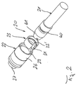
- a locking device provided as a whole with the reference character 20 comprises two studs 21 held on the insulating housing 13, two location sleeves 22 disposed on the insulating housing 16, as well as a spring clip 23 for locking location of the stud 21.
- the location sleeve 22 comprises a cylindrical main part 26 and, formed on the latter, a smaller-diameter fastening part 27 for the printed-board connector part 11.
- the main part 26 of the location sleeve 22 has, incorporated in its inner periphery, an undercut peripheral groove 28 as well as, at its end (remote from the fastening part 27), a lead-in cone 29.
- the spring clip 23 is a relatively wide, annular or bush-shaped, unilaterally slotted and hence open, radially resilient component.
- the spring clip ring 23 provided with the axial peripheral slot 31 has, midway along its length, a radially inward-moulded portion 32 (according to Figs. 3 and 4) or an inner moulded-on portion 32' (Fig. 2), which at the inside of the ring has a front slope 33 and a back slope 34 as well as an inner flat surface 35 arranged concentrically with the outer periphery.
- the spring clip 23 is integrally formed from a metal, preferably spring steel. In the state of rest, the outside diameter of the spring clip 23 is slightly greater than the inside diameter of the location sleeve 22.
- Insertion of the spring clip 23 into the location sleeve 22 is therefore effected in such a way that the spring clip 23 is introduced in a slightly compressed state via the lead-in cone 29 into the location sleeve 22 and displaced axially as far as into the region of the inner peripheral groove 28, in which the spring clip 23 may expand radially.
- the spring clip 23 over a partial region of its thickness is situated in the inner peripheral groove 28.
- the axial width of the spring clip 23 is moreover smaller than the axial width of the inner peripheral groove 28, with the result that manufacturing tolerances and hence fitting tolerances of stud 21 and location sleeve 22 may be absorbed.
- the stud 21 has a conical lead-in slope 41 and an outer peripheral groove 40 extending at right angles to the direction of insertion.
- An, in the direction of insertion, front groove wall of the outer peripheral groove 40 has a region 43, which is bevelled towards the front end of the stud 21 and verges, towards the groove base, into a wall region 44 at right angles to the direction of insertion.
- the outer peripheral groove 40 or its groove base is of a stepped design in the, in direction of insertion, back region, wherein a front and radially inner step region 46 is delimited by the groove wall region 44 extending substantially at right angles to the direction of insertion. This allows the connector parts 11 and 12 to be used with a sliding locking device, the slide element 47 of which is indicated in Fig. 4.
- the stud 21 When the stud 21 is introduced into the location sleeve 22 during connection of the two connector parts 11, 12, the stud 21 is centred by the lead-in slope 41 of the location sleeve 22 and the spring clip 23 is expanded radially outwards into the inner peripheral groove 28, wherein the latter slides along a shell portion 48 of the stud 21.
- the outer peripheral groove 40 of the stud 21 arrives in the region of the radially protruding inward-moulded portion 32 of the spring clip 23
- the inward-moulded portion 32 of the spring clip 23 slides over the bevelled groove edge region 43 and latches into the peripheral groove 40 of the stud 21 and hence locks the two connector parts 11 and 12.
- the stud 21 further has a threaded bore 49 extending in the direction of its longitudinal axis so that the stud may be used for locking with a corresponding screw connection of the other connector part.
- the two slopes 33 and 34 of the spring clip 23 are equiangular, with the result that insertion force and extraction force are approximately equal, and the inward-moulded part 32 is disposed midway along the length of the spring clip 32 so that during assembly there is no need to pay attention to orientation.
- the angles of the two slopes 33, 34 may alternatively be selected so as to differ so that, for example, the extraction force (or the insertion force) may be selected so as to be greater; in said case a possibly eccentric position of the inward-moulded portion on the spring clip may facilitate the orientation during assembly.
Landscapes
- Details Of Connecting Devices For Male And Female Coupling (AREA)
Abstract
Description
- Fig. 1
- a plan view of two connector parts of a connector according to a preferred embodiment of the present invention,
- Fig. 2
- an exploded perspective view of a location sleeve plus spring clip and a stud, to be connected thereto, of the connector according to Fig. 1,
- Fig. 3
- a longitudinal section of the location sleeve with introduced spring clip, and
- Fig. 4
- a longitudinal section of the location sleeve with introduced spring clip and with latchingly inserted stud.
Claims (7)
- Connector, having two connector parts (11, 12), in particular in the form of a male connector and a female connector, which each comprise an insulating housing (13, 16) and a contact arrangement (14, 17) held thereon and connectable to the contact arrangement of the other insulating housing, and having a locking device (20), which comprises at least one stud (21) extending in direction of insertion on the one connector part (11) and at least one location sleeve (22) for the stud (21) on the other connector part (12), wherein the stud (21) has an outer peripheral groove (40), which extends substantially at right angles to the direction of insertion and into which a resilient locking element in the form of a bush-shaped, unilaterally slotted spring clip (23) movable in the location sleeve (22) at right angles to the direction of insertion is latchable, which is axially received and held in a radially expandable manner in an inner peripheral groove (28) of the location sleeve (22) and which comprises a radially inward-moulded portion (32) for locking location in the outer peripheral groove (28) of the stud (21), characterized in that the radially inward-moulded portion (32) is provided so as to extend over the entire inner periphery of the unilaterally slotted spring clip (23) and is provided with a front and a back insertion and/or extraction slope (33, 34).
- Connector according to claim 1, characterized in that the inward-moulded portion (32) is disposed midway along the length of the spring clip (23) and that its slopes (33, 34) are disposed symmetrically relative to one another.
- Connector according to claim 1, characterized in that the one slope (33, 34) is steeper than the other (34, 33).
- Connector according to at least one of the preceding claims, characterized in that the depth of the inner peripheral groove (28) of the location sleeve (22) is greater than corresponds to the thickness of the spring clip (23).
- Connector according to one of the preceding claims, characterized in that the width of the inner peripheral groove (28) of the location sleeve (22) is greater than that of the spring clip (23).
- Connector according to at least one of the preceding claims, characterized in that the front groove wall of the outer peripheral groove (40) of the stud (21) has an outer region (43), which is bevelled towards the stud shell and inclined relative to the direction of insertion, and an inner region (44) substantially at right angles to the direction of insertion.
- Connector according to claim 6, characterized in that the groove base (36) of the outer peripheral groove (40) of the stud (21) is of a stepped design.
Applications Claiming Priority (2)
| Application Number | Priority Date | Filing Date | Title |
|---|---|---|---|
| DE19945784 | 1999-09-24 | ||
| DE19945784A DE19945784C1 (en) | 1999-09-24 | 1999-09-24 | Connectors |
Publications (2)
| Publication Number | Publication Date |
|---|---|
| EP1087469A2 true EP1087469A2 (en) | 2001-03-28 |
| EP1087469A3 EP1087469A3 (en) | 2003-08-27 |
Family
ID=7923155
Family Applications (1)
| Application Number | Title | Priority Date | Filing Date |
|---|---|---|---|
| EP00119538A Withdrawn EP1087469A3 (en) | 1999-09-24 | 2000-09-07 | Electrical connector |
Country Status (3)
| Country | Link |
|---|---|
| US (1) | US6398574B1 (en) |
| EP (1) | EP1087469A3 (en) |
| DE (1) | DE19945784C1 (en) |
Cited By (1)
| Publication number | Priority date | Publication date | Assignee | Title |
|---|---|---|---|---|
| EP2284959B1 (en) * | 2009-08-11 | 2015-05-27 | CoActive Technologies, LLC | Improved device for latching a connector device |
Families Citing this family (4)
| Publication number | Priority date | Publication date | Assignee | Title |
|---|---|---|---|---|
| DE10110343A1 (en) * | 2001-03-03 | 2002-09-12 | Bosch Gmbh Robert | plug-in device |
| US6752668B2 (en) * | 2002-08-14 | 2004-06-22 | Konnektech, Ltd. | Electrical connector |
| JP5806313B2 (en) * | 2010-08-25 | 2015-11-10 | カーディアック ペースメイカーズ, インコーポレイテッド | Apparatus and method for attaching header to housing of embedded device |
| CN210296752U (en) * | 2019-07-22 | 2020-04-10 | 深圳市川特电子科技有限公司 | Cable connection structure |
Family Cites Families (6)
| Publication number | Priority date | Publication date | Assignee | Title |
|---|---|---|---|---|
| DE1465280A1 (en) * | 1964-04-23 | 1969-04-30 | Bosch Gmbh Robert | Plug connection for electrical lines |
| DE2143434B2 (en) * | 1971-08-30 | 1973-08-30 | LATCH CLOSURE FOR COAXIAL CONNECTORS | |
| US4906211A (en) * | 1987-01-30 | 1990-03-06 | Wyle Laboratories | Connector for aircraft-to-ground maintenance electrical connection |
| IT1208261B (en) * | 1987-03-25 | 1989-06-12 | Connei Spa | COMPOSITE FEMALE CONTACT FOR RECEIVING A PIN-TYPE MALE CONTACT |
| US5533914A (en) * | 1994-12-27 | 1996-07-09 | Yazaki Corporation | Electrical connection terminal |
| DE19526248C2 (en) * | 1995-07-18 | 1999-04-08 | Itt Cannon Gmbh | Connectors |
-
1999
- 1999-09-24 DE DE19945784A patent/DE19945784C1/en not_active Expired - Fee Related
-
2000
- 2000-09-07 EP EP00119538A patent/EP1087469A3/en not_active Withdrawn
- 2000-09-19 US US09/664,935 patent/US6398574B1/en not_active Expired - Fee Related
Cited By (1)
| Publication number | Priority date | Publication date | Assignee | Title |
|---|---|---|---|---|
| EP2284959B1 (en) * | 2009-08-11 | 2015-05-27 | CoActive Technologies, LLC | Improved device for latching a connector device |
Also Published As
| Publication number | Publication date |
|---|---|
| DE19945784C1 (en) | 2001-03-29 |
| US6398574B1 (en) | 2002-06-04 |
| EP1087469A3 (en) | 2003-08-27 |
Similar Documents
| Publication | Publication Date | Title |
|---|---|---|
| US6695636B2 (en) | Lockable electrical connector | |
| US7455549B2 (en) | Coaxial cable connector with friction-fit sleeve | |
| CA1041626A (en) | Positive locking electrical connector | |
| KR100474652B1 (en) | A connector for terminating an end of coaxial cable and a method for terminating an end of coaxial cable | |
| US4334730A (en) | Insulated from ground bulkhead adapter | |
| US20020019161A1 (en) | Circular connector | |
| JP2006526262A (en) | Electrical plug connection | |
| US5938486A (en) | Female electrical contact member and electrical connector housing member adapted to receive a member of this kind | |
| JPH07235349A (en) | Ultra-small coaxial connector that locks by snapping | |
| CN116315886B (en) | Circular connector | |
| JPH11341650A (en) | Grommet | |
| JP2000091014A (en) | Terminal fitting | |
| US2935720A (en) | Waterproof connector | |
| EP1017261A2 (en) | Grounding circuit board standoff | |
| US8068060B2 (en) | Combination of tube assembly and clip for wireless antenna grounding | |
| US6485329B2 (en) | Connecting element for two items of installation equipment lined up beside each other with their broad sides against each other, and method of connecting the items of installation equipment | |
| US5791932A (en) | Releasable connector assembly | |
| US20080214028A1 (en) | Plug with Retainer Spring for an Earth Contact | |
| HK1033038A (en) | Electrical connector | |
| CA1068366A (en) | Lamp socket assembly affording variable bulb focal length positioning | |
| US6398574B1 (en) | Sleeve and stud connector latch | |
| US4734057A (en) | Connector assembly | |
| US3090937A (en) | Electrical connector with contact retention sleeve | |
| US6615055B1 (en) | Structure of rod antenna guide port in cellular telephone | |
| US20040219834A1 (en) | Coaxial cable coupler, especially an antenna coupler |
Legal Events
| Date | Code | Title | Description |
|---|---|---|---|
| PUAI | Public reference made under article 153(3) epc to a published international application that has entered the european phase |
Free format text: ORIGINAL CODE: 0009012 |
|
| AK | Designated contracting states |
Kind code of ref document: A2 Designated state(s): AT BE CH CY DE DK ES FI FR GB GR IE IT LI LU MC NL PT SE |
|
| AX | Request for extension of the european patent |
Free format text: AL;LT;LV;MK;RO;SI |
|
| PUAL | Search report despatched |
Free format text: ORIGINAL CODE: 0009013 |
|
| AK | Designated contracting states |
Designated state(s): AT BE CH CY DE DK ES FI FR GB GR IE IT LI LU MC NL PT SE |
|
| AX | Request for extension of the european patent |
Extension state: AL LT LV MK RO SI |
|
| RIC1 | Information provided on ipc code assigned before grant |
Ipc: 7H 01R 13/621 B Ipc: 7H 01R 13/627 A |
|
| 17P | Request for examination filed |
Effective date: 20030723 |
|
| GRAP | Despatch of communication of intention to grant a patent |
Free format text: ORIGINAL CODE: EPIDOSNIGR1 |
|
| AKX | Designation fees paid |
Designated state(s): AT BE CH CY DE DK ES FI FR GB GR IE IT LI LU MC NL PT SE |
|
| STAA | Information on the status of an ep patent application or granted ep patent |
Free format text: STATUS: THE APPLICATION IS DEEMED TO BE WITHDRAWN |
|
| 18D | Application deemed to be withdrawn |
Effective date: 20040813 |
|
| REG | Reference to a national code |
Ref country code: HK Ref legal event code: WD Ref document number: 1033038 Country of ref document: HK |