EP1087466A2 - Electrical connector - Google Patents
Electrical connector Download PDFInfo
- Publication number
- EP1087466A2 EP1087466A2 EP00119537A EP00119537A EP1087466A2 EP 1087466 A2 EP1087466 A2 EP 1087466A2 EP 00119537 A EP00119537 A EP 00119537A EP 00119537 A EP00119537 A EP 00119537A EP 1087466 A2 EP1087466 A2 EP 1087466A2
- Authority
- EP
- European Patent Office
- Prior art keywords
- printed
- circuit board
- plug
- connector
- connector according
- Prior art date
- Legal status (The legal status is an assumption and is not a legal conclusion. Google has not performed a legal analysis and makes no representation as to the accuracy of the status listed.)
- Withdrawn
Links
Images

Classifications
-
- H—ELECTRICITY
- H01—ELECTRIC ELEMENTS
- H01R—ELECTRICALLY-CONDUCTIVE CONNECTIONS; STRUCTURAL ASSOCIATIONS OF A PLURALITY OF MUTUALLY-INSULATED ELECTRICAL CONNECTING ELEMENTS; COUPLING DEVICES; CURRENT COLLECTORS
- H01R12/00—Structural associations of a plurality of mutually-insulated electrical connecting elements, specially adapted for printed circuits, e.g. printed circuit boards [PCB], flat or ribbon cables, or like generally planar structures, e.g. terminal strips, terminal blocks; Coupling devices specially adapted for printed circuits, flat or ribbon cables, or like generally planar structures; Terminals specially adapted for contact with, or insertion into, printed circuits, flat or ribbon cables, or like generally planar structures
- H01R12/70—Coupling devices
- H01R12/7005—Guiding, mounting, polarizing or locking means; Extractors
- H01R12/7011—Locking or fixing a connector to a PCB
- H01R12/7064—Press fitting
Definitions
- the present invention relates to a connector according to the preamble of claim 1.
- the device for fastening and retaining the connector housing on the printed-circuit board or the like comprises a fixing angle, a sleeve element axially slit at one end and an internally threaded sleeve.
- Said three components have to be assembled in such a way that the sleeve element is fastened to the fixing angle and penetrates one end of the latter to such an extent that its outwardly projecting, axially slit end region fits in a radially resilient manner into a plated-through hole of the printed-circuit board, and that the internally threaded sleeve is connected, with the interposition of a connector housing region, by soldering or compression to the other end of the fixing angle.
- This is costly, both in terms of manufacture and assembly.
- the object of the present invention is therefore to provide a connector of the type described initially, which is easier to assemble in the region of the fastening and retaining device for plug-in connection to a printed-circuit board and the fastening and retaining device of which takes up less surface area on the printed-circuit board.
- the pin-like element may be connected quickly and easily to the printed-circuit board.
- the pin-like refinement only a little more surface area is taken up around the plated-through hole in the printed-circuit board.
- a positionally accurate association of the contact elements with the printed-circuit board is achieved by the features according to claim 3. In said case, it is advantageous to provide the features according to claim 4.
- the connector may, for example, be disposed at right angles to the surface of the printed-circuit board and connected to the latter.
- a parallel, low-lying arrangement of the connector relative to the printed-circuit board is achieved.
- the pin-like element may be threaded by its end used for the connection to the printed-circuit board through the receiver of the connector housing.
- the connector housing is advantageously refined in accordance with the features of claim 11.
- a further improvement and simplification of the assembly and/or plug-in connection of the connector on a printed-circuit board simultaneously combined with the simplest possible design of a suitable assembly tool is achieved when the features according to claim 12 are provided.
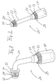
- the connector 10 illustrated in Fig. 1 is connectable by its front end to a printed-circuit board 11 or the like, which is merely indicated by dash-dot lines, and is used at its back end to receive in a removable manner a non-illustrated matching plug.
- the connector 10 lies parallel to the surface 12 of the printed-circuit board 11 and is connectable to the latter simply by insertion in the direction of the arrow A.
- the connector 10 has a two-part connector housing 16, of which the back housing part 17 is used to receive the non-illustrated plug in a removable, latchable manner and the front housing part 18 holds a plurality of electrical contact elements 19, which penetrate as far as into the back housing part 17.
- the two housing parts 17 and 18, which in their main region are formed in a hollow manner, have laterally protruding wings 21, 22, which are each provided with a drilled hole 24 and are connected to one another by crimping and are used to receive a fastening and retaining device 23 for fixing and retaining the connector housing 16 in the correct position and in a correctly fitting manner against the printed-circuit board 11.
- the fastening and retaining device 23 comprises two identical, integral pin-like elements 26, further details of which are shown in Fig. 2.
- the pin element 26 formed from a metal comprises a middle pin region 27 bent at an angle, here at right angles, the shorter portion of which is equipped with a plug-in end 28 for a plated-through hole of the printed-circuit board 11 and the longer portion of which is equipped with a plug-in region 29 for the connector housing 16.
- the plug-in end 28 for the printed-circuit board 11 has an axial tooth system 31, which is arranged so as to be distributed uniformly over its periphery and verges at the free end into a smooth cone 32.
- the plug-in end 28 has an insertion-limiting stop in the form of an annular collar 33.
- the outside diameter of the relatively tapering- and sharp-edged tooth system 31 is designed for a so-called press fit, i.e. the outside diameter is minimally greater than the inside diameter of the plated-through hole of the printed-circuit board 11 so that by virtue of the tooth system 31 cutting into the inner periphery of the plated-through hole of the printed-circuit board both an electrical contacting and a mechanical press-fit connection is achieved.
- the plug-in region 29, like the plug-in end 28, is provided with an axial tooth system 36 arranged so as to be distributed uniformly over its periphery. Said region of the tooth system 36 verges via a smooth cone 37 into the adjoining portion of the pin region 27 and is covered at the other end by a coaxial internally threaded sleeve 38.
- the axial length of the tooth system 36 corresponds approximately to the thickness of the wings 21 and 22 of the connector housing 16, just as the axial length of the tooth system 31 corresponds to the thickness of the printed-circuit board 11.
- the internally threaded sleeve 38 has a diameter slightly greater than the tooth system 36 so that its annular end face 39 serves as an insertion-limiting stop and lies against the wing 21 of the back housing part 17.
- the internal thread of the sleeve 38 is used to screw-fasten a non-illustrated plug, which is to be inserted into the connector housing 16.
- the outside diameter of the relatively tapering- and sharp-edged tooth system 36 is minimally greater than the inside diameter of the drilled hole 24 in the wings 21, 22 so that, here too, a so-called press fit arises.
- the pin element 26 is manufactured in a suitable manner in accordance with Fig. 3 as a straight component 26'.
- the pin element 26' in its pin region 27' having the smallest diameter is bent into the pin region 27 extending at right angles (Fig. 2).
- the bent pin element 26 is threaded by its front end having the cone 32 through the drilled hole 24 in the wings 21 and 22 of the connector housing 16 and is then pressed with the aid of the tooth system 36 in the correct position into the drilled hole 24 and retained by means of the said press fit.
- the pressing of the tooth system 36 into the housing wings 21 and 22 is effected until the annular end face 39 rests against the back housing part wing 21.
- the connector 10 is placed with the aid of a further tool (not shown) onto the printed-circuit board 11, wherein both the pin elements 26 of the fastening and retaining device 23 with their plug-in ends 28 and the ends 42, yet to be described, of the electrical contact elements 19 are pressed into the respective plated-through holes of the printed-circuit board 11.
- the non-illustrated tool is applied against the end or face of the annular collar 33 of the pin element 26 remote from the tooth system 31, thereby allowing the application of a force for pressing the tooth system 31 into the plated-through hole of the printed-circuit board 11.
- the pin elements 26 are electrically and mechanically connected or secured to the printed-circuit board 11 and fixed.
- the electrical contact elements 19 comprise contact ends 41 and 42, which are disposed at right angles to one another and of which the contact ends 41 are held in the housing 16 and the contact ends 42 are equipped with an axially slit resilient receiver 43.
- Said receiver 43 is disposed substantially in the plane of the tooth system 31 of the pin elements 26 so that, with insertion of the pin elements 26 into the printed-circuit board, the radially resilient receivers 43 of the contact elements 19 simultaneously move into the corresponding plated-through holes and establish electrical contact with the printed-circuit board 11.
- the contact elements 19 are of a right-angled design. Their components forming the resilient receiver 43 have in axial extension of the receiver 43 a flat surface 44, against which the previously described assembly tool may optionally be additionally applied.
- peripheral surface or core e.g. a slot or groove
- other configurations of the peripheral surface or core e.g. a slot or groove, are possible for achieving a press fit in the respective hole.
- the mounting of the connector 10 on the printed-circuit board 11 is effected in such a way that the connector 10 is disposed parallel to the surface 12 of the printed-circuit board 11 and the press-in connecting motion is effected at right angles to the printed-circuit board surface 12.
- the pin elements 26 may be used also in the straight manner illustrated in Fig. 3 when the connector 10 is to be disposed, not parallel, but at right angles to the surface 12 of the printed-circuit board 11. It is further self-evident that the pin elements 26 may be bent, not at right angles, but at an obtuse angle when a corresponding position of the connector 10 relative to the surface 12 of the printed-circuit board is desired and/or necessary.
Abstract
Description
- Fig. 1
- a perspective view of a connector according to a preferred embodiment of the present invention;
- Fig. 2
- an enlarged perspective view of a bent pin-like element for fastening and retaining the connector on a printed-circuit board; and
- Fig. 3
- a view as in Fig. 2 but of a straight pin-like fastening and retaining element.
Claims (12)
- Connector (10), having a plurality of electrical contact elements (19), which are disposed inside a connector housing (16) and provided with a first connection end, e.g. for a plug, and a second connection end (43) for plug-in connection to plated-through holes of a printed-circuit board (11) or the like, and having a device (23) for fastening and retaining the connector housing (16) in a correctly fitting manner
characterized in
that the fastening and retaining device (23) comprises an integral pin-like element (26), which at its plug-in end (28) for the plated-through hole of the printed-circuit board (11) is so designed that it may be brought together in the manner of a press fit with the plated-through hole of the printed-circuit board. - Connector according to claim 1, characterized in that the element (26) at its plug-in end (28) for the plated-through hole of the printed-circuit board (11) is designed with axial gearing extending over its periphery, wherein the tooth system (31) and the plated-through hole of the printed-circuit board may be brought together in the manner of a press fit.
- Connector according to claim 1 or 2, characterized in that the plug-in end (28) of the pin-like element (26) is provided with an insertion-limiting stop (33).
- Connector according to claim 3, characterized in that the insertion-limiting stop is formed by the collar (33) of a disk.
- Connector according to at least one of claims 1 to 4, characterized in that the pin-like element (26) is bent at an angle, preferably at right angles.
- Connector according to at least one of the preceding claims, characterized in that the pin-like element (26) at its plug-in region (29) for the connector housing (16) is designed with axial gearing extending over its periphery, wherein tooth system (36) and connector housing drilled hole (24) may be brought together in the manner of a press fit.
- Connector according to claim 6, characterized in that the plug-in region (29) is provided with an insertion-limiting stop (39).
- Connector according to claim 7, characterized in that the insertion-limiting stop is formed by the collar (39) of a cylinder element (38).
- Connector according to claim 8, characterized in that the cylinder element (38) has an internal thread.
- Connector according to at least one of the preceding claims, characterized in that the plug-in end (28) has a smaller diameter than the plug-in region (29).
- Connector according to at least one of the preceding claims, characterized in that the connector housing (16) has two lateral wings (21, 22), in each of which a pin-like element (26) is held.
- Connector according to at least one of the preceding claims, characterized in that the integral pin-like element (26) is provided with an application region for a force acting in the direction of insertion.
Applications Claiming Priority (2)
| Application Number | Priority Date | Filing Date | Title |
|---|---|---|---|
| DE19945310A DE19945310C2 (en) | 1999-09-22 | 1999-09-22 | Connectors |
| DE19945310 | 1999-09-22 |
Publications (2)
| Publication Number | Publication Date |
|---|---|
| EP1087466A2 true EP1087466A2 (en) | 2001-03-28 |
| EP1087466A3 EP1087466A3 (en) | 2003-04-16 |
Family
ID=7922833
Family Applications (1)
| Application Number | Title | Priority Date | Filing Date |
|---|---|---|---|
| EP00119537A Withdrawn EP1087466A3 (en) | 1999-09-22 | 2000-09-07 | Electrical connector |
Country Status (3)
| Country | Link |
|---|---|
| US (1) | US6386911B1 (en) |
| EP (1) | EP1087466A3 (en) |
| DE (1) | DE19945310C2 (en) |
Cited By (2)
| Publication number | Priority date | Publication date | Assignee | Title |
|---|---|---|---|---|
| GB2383904A (en) * | 2002-01-07 | 2003-07-09 | Litton Systems Inc | High speed, high density interconnect system for differential and single-ende d transmission systems on backplane / motherboards |
| DE10259803B3 (en) * | 2002-12-19 | 2004-05-13 | Kathrein-Werke Kg | Electrical termination connection for outer conductor of coaxial cable has plug part with 2 plug sections fitting into housing wall opening with 2 reception sections |
Families Citing this family (2)
| Publication number | Priority date | Publication date | Assignee | Title |
|---|---|---|---|---|
| DE102018202528A1 (en) * | 2018-02-20 | 2019-08-22 | Zf Friedrichshafen Ag | press connection |
| DE102020208149A1 (en) * | 2020-06-30 | 2021-12-30 | Te Connectivity Germany Gmbh | Module connector |
Citations (4)
| Publication number | Priority date | Publication date | Assignee | Title |
|---|---|---|---|---|
| US4717219A (en) * | 1986-06-19 | 1988-01-05 | Amp Incorporated | Electrical connector and assembly eyelets |
| US4927372A (en) * | 1988-02-19 | 1990-05-22 | Itt Industries Limited | Electrical connector |
| DE9311439U1 (en) * | 1993-07-31 | 1993-12-02 | Wuerth Elektronik Gmbh & Co Kg | Attachment of a plug and / or socket element |
| US5816855A (en) * | 1995-11-07 | 1998-10-06 | Framatome Connectors International | Holding and contact element and connector |
Family Cites Families (8)
| Publication number | Priority date | Publication date | Assignee | Title |
|---|---|---|---|---|
| DE7422768U (en) * | 1974-07-04 | 1974-11-14 | Kontaktron Gmbh | Solderless electrical connection |
| US4911659A (en) * | 1989-04-21 | 1990-03-27 | Amp Incorporated | Electrical connector and a retention bracket therefor |
| US5074807A (en) * | 1990-12-03 | 1991-12-24 | Amp Incorporated | Component holding device |
| DE9202303U1 (en) * | 1992-02-22 | 1993-06-17 | Presskontakt Ing. Grad. Hartmuth Thaler Kg, 7110 Oehringen, De | |
| US6045401A (en) * | 1997-09-26 | 2000-04-04 | The Whitaker Corporation | Connector-mounting member |
| US6095853A (en) * | 1997-12-30 | 2000-08-01 | Hon Hai Precison Ind. Co., Ltd. | Connector assembly |
| JP2000058165A (en) * | 1998-08-03 | 2000-02-25 | Fujitsu Takamisawa Component Ltd | Connector |
| TW383971U (en) * | 1998-11-03 | 2000-03-01 | Hon Hai Prec Ind Co Ltd | Fastening apparatus for electronic device |
-
1999
- 1999-09-22 DE DE19945310A patent/DE19945310C2/en not_active Expired - Fee Related
-
2000
- 2000-09-07 EP EP00119537A patent/EP1087466A3/en not_active Withdrawn
- 2000-09-18 US US09/664,978 patent/US6386911B1/en not_active Expired - Lifetime
Patent Citations (4)
| Publication number | Priority date | Publication date | Assignee | Title |
|---|---|---|---|---|
| US4717219A (en) * | 1986-06-19 | 1988-01-05 | Amp Incorporated | Electrical connector and assembly eyelets |
| US4927372A (en) * | 1988-02-19 | 1990-05-22 | Itt Industries Limited | Electrical connector |
| DE9311439U1 (en) * | 1993-07-31 | 1993-12-02 | Wuerth Elektronik Gmbh & Co Kg | Attachment of a plug and / or socket element |
| US5816855A (en) * | 1995-11-07 | 1998-10-06 | Framatome Connectors International | Holding and contact element and connector |
Cited By (4)
| Publication number | Priority date | Publication date | Assignee | Title |
|---|---|---|---|---|
| GB2383904A (en) * | 2002-01-07 | 2003-07-09 | Litton Systems Inc | High speed, high density interconnect system for differential and single-ende d transmission systems on backplane / motherboards |
| GB2383904B (en) * | 2002-01-07 | 2005-03-09 | Litton Systems Inc | Interconnection system |
| DE10259803B3 (en) * | 2002-12-19 | 2004-05-13 | Kathrein-Werke Kg | Electrical termination connection for outer conductor of coaxial cable has plug part with 2 plug sections fitting into housing wall opening with 2 reception sections |
| US7056148B2 (en) | 2002-12-19 | 2006-06-06 | Kathrein-Werke Kg | Electrical terminal connection, especially for connecting an outer conductor of a coaxial cable |
Also Published As
| Publication number | Publication date |
|---|---|
| DE19945310C2 (en) | 2001-11-08 |
| US6386911B1 (en) | 2002-05-14 |
| EP1087466A3 (en) | 2003-04-16 |
| DE19945310A1 (en) | 2001-04-19 |
Similar Documents
| Publication | Publication Date | Title |
|---|---|---|
| EP3213374B1 (en) | Power connector | |
| EP2183828B1 (en) | Hyperboloid electrical contact | |
| US6328615B1 (en) | Contact formed of joined pieces | |
| JP2002260792A (en) | Plug in connector | |
| CA2425339A1 (en) | Coaxial connector | |
| WO2011143807A1 (en) | Contact spring for plug connector socket | |
| US5571033A (en) | Electrical connector having press-fit contacts for circuit board mounting | |
| JPH09106841A (en) | Electric connector | |
| US11211732B2 (en) | Plug-in connector part with caulked contact elements and method for producing said plug-in connector part | |
| US20030224658A1 (en) | Electrical connector | |
| EP1087466A2 (en) | Electrical connector | |
| US6056596A (en) | Connecting coupler for a printed-circuit board | |
| US10096922B2 (en) | Rearview mirror assembly with biased electrical connection | |
| JP2014093172A (en) | Terminal | |
| JP2570456B2 (en) | Electrical connector for card mounting | |
| JP2021504891A (en) | Plug connector | |
| JPH11307158A (en) | Coaxial connector | |
| EP3669424B1 (en) | Connector for printed circuit board | |
| JPH0660067U (en) | Surface mount connector fixing structure | |
| US20170005449A1 (en) | Method for mounting a multiple-contact press-fit connector | |
| EP0954058A2 (en) | Flexible circuit electrical connector assembly | |
| JP3009610U (en) | Crimping structure of connector and shield case | |
| JP2022527838A (en) | Multi-pole electrical connector | |
| KR200349425Y1 (en) | terminal for electronic contactor | |
| US5993271A (en) | CATV housing seizure mechanism for receiving hardline coaxial cable pin connectors |
Legal Events
| Date | Code | Title | Description |
|---|---|---|---|
| PUAI | Public reference made under article 153(3) epc to a published international application that has entered the european phase |
Free format text: ORIGINAL CODE: 0009012 |
|
| AK | Designated contracting states |
Kind code of ref document: A2 Designated state(s): AT BE CH CY DE DK ES FI FR GB GR IE IT LI LU MC NL PT SE |
|
| AX | Request for extension of the european patent |
Free format text: AL;LT;LV;MK;RO;SI |
|
| PUAL | Search report despatched |
Free format text: ORIGINAL CODE: 0009013 |
|
| AK | Designated contracting states |
Designated state(s): AT BE CH CY DE DK ES FI FR GB GR IE IT LI LU MC NL PT SE |
|
| AX | Request for extension of the european patent |
Extension state: AL LT LV MK RO SI |
|
| AKX | Designation fees paid | ||
| REG | Reference to a national code |
Ref country code: DE Ref legal event code: 8566 |
|
| STAA | Information on the status of an ep patent application or granted ep patent |
Free format text: STATUS: THE APPLICATION IS DEEMED TO BE WITHDRAWN |
|
| 18D | Application deemed to be withdrawn |
Effective date: 20031017 |
|
| REG | Reference to a national code |
Ref country code: HK Ref legal event code: WD Ref document number: 1033037 Country of ref document: HK |