EP1087418A1 - Colour selection mask for cathode ray tube - Google Patents
Colour selection mask for cathode ray tube Download PDFInfo
- Publication number
- EP1087418A1 EP1087418A1 EP00120729A EP00120729A EP1087418A1 EP 1087418 A1 EP1087418 A1 EP 1087418A1 EP 00120729 A EP00120729 A EP 00120729A EP 00120729 A EP00120729 A EP 00120729A EP 1087418 A1 EP1087418 A1 EP 1087418A1
- Authority
- EP
- European Patent Office
- Prior art keywords
- mask
- ray tube
- cathode
- tube according
- mechanical
- Prior art date
- Legal status (The legal status is an assumption and is not a legal conclusion. Google has not performed a legal analysis and makes no representation as to the accuracy of the status listed.)
- Granted
Links
- 229910052751 metal Inorganic materials 0.000 claims abstract description 26
- 239000002184 metal Substances 0.000 claims abstract description 26
- 230000002093 peripheral effect Effects 0.000 claims abstract description 9
- 238000005520 cutting process Methods 0.000 claims abstract description 4
- 238000013016 damping Methods 0.000 claims description 9
- 239000011888 foil Substances 0.000 claims description 5
- 239000011248 coating agent Substances 0.000 claims description 4
- 238000000576 coating method Methods 0.000 claims description 4
- 238000005530 etching Methods 0.000 claims description 3
- 229910001385 heavy metal Inorganic materials 0.000 claims description 2
- 239000003086 colorant Substances 0.000 abstract description 2
- 238000010894 electron beam technology Methods 0.000 description 4
- 238000003491 array Methods 0.000 description 3
- 238000004519 manufacturing process Methods 0.000 description 3
- OAICVXFJPJFONN-UHFFFAOYSA-N Phosphorus Chemical compound [P] OAICVXFJPJFONN-UHFFFAOYSA-N 0.000 description 2
- 239000011521 glass Substances 0.000 description 2
- 239000000463 material Substances 0.000 description 2
- 238000000034 method Methods 0.000 description 2
- 230000010355 oscillation Effects 0.000 description 2
- 230000035939 shock Effects 0.000 description 2
- 238000003466 welding Methods 0.000 description 2
- 229910001374 Invar Inorganic materials 0.000 description 1
- ZOKXTWBITQBERF-UHFFFAOYSA-N Molybdenum Chemical compound [Mo] ZOKXTWBITQBERF-UHFFFAOYSA-N 0.000 description 1
- 229910000831 Steel Inorganic materials 0.000 description 1
- 238000000151 deposition Methods 0.000 description 1
- 238000002845 discoloration Methods 0.000 description 1
- 238000006073 displacement reaction Methods 0.000 description 1
- 230000000694 effects Effects 0.000 description 1
- 238000005516 engineering process Methods 0.000 description 1
- 238000007496 glass forming Methods 0.000 description 1
- 230000002045 lasting effect Effects 0.000 description 1
- 229910052750 molybdenum Inorganic materials 0.000 description 1
- 239000011733 molybdenum Substances 0.000 description 1
- 230000021715 photosynthesis, light harvesting Effects 0.000 description 1
- 230000003014 reinforcing effect Effects 0.000 description 1
- 239000010959 steel Substances 0.000 description 1
- 239000000725 suspension Substances 0.000 description 1
- WFKWXMTUELFFGS-UHFFFAOYSA-N tungsten Chemical compound [W] WFKWXMTUELFFGS-UHFFFAOYSA-N 0.000 description 1
- 229910052721 tungsten Inorganic materials 0.000 description 1
- 239000010937 tungsten Substances 0.000 description 1
Images



Classifications
-
- H—ELECTRICITY
- H01—ELECTRIC ELEMENTS
- H01J—ELECTRIC DISCHARGE TUBES OR DISCHARGE LAMPS
- H01J29/00—Details of cathode-ray tubes or of electron-beam tubes of the types covered by group H01J31/00
- H01J29/02—Electrodes; Screens; Mounting, supporting, spacing or insulating thereof
- H01J29/06—Screens for shielding; Masks interposed in the electron stream
- H01J29/07—Shadow masks for colour television tubes
-
- H—ELECTRICITY
- H01—ELECTRIC ELEMENTS
- H01J—ELECTRIC DISCHARGE TUBES OR DISCHARGE LAMPS
- H01J2229/00—Details of cathode ray tubes or electron beam tubes
- H01J2229/07—Shadow masks
- H01J2229/0727—Aperture plate
- H01J2229/0738—Mitigating undesirable mechanical effects
- H01J2229/0744—Vibrations
Definitions
- the present invention relates to a colour selection mask structure for a colour cathode-ray tube and more particularly to a mask structure designed to be held under tension inside the said tube.
- the invention is applicable in any type of tube having a colour selection mask and is particularly suitable for tubes whose mask is held under tension by the frame to which it is fastened.
- Conventional cathode-ray tubes include a colour selection mask located at a precise distance from the inside of the glass faceplate of the tube, on which faceplate arrays of red, green and blue phosphors are deposited in order to form a screen.
- An electron gun placed inside the tube, in its rear part, generates three electron beams in the direction of the faceplate.
- An electromagnetic deflection device generally placed outside the tube and close to the electron gun, has the function of deflecting the electron beams so as to make them scan the surface of the panel on which the arrays of phosphors are arranged. Under the influence of the three electron beams each corresponding to a predetermined primary colour, the arrays of phosphors make it possible to reproduce images on the screen, the mask allowing each predetermined beam to illuminate only the phosphor of the corresponding colour.
- the colour selection mask must be placed in a precise position inside the tube and supported therein during the operation of the tube.
- the support functions of the mask are achieved by means of a generally very rigid rectangular metal frame to which the mask is conventionally welded.
- the frame/mask assembly is mounted in the faceplate of the tube using suspension means welded to the frame and interacting with pins inserted into the glass forming the faceplate of the tube.
- Tubes having such a faceplate are produced using a technology which consists in using a plane mask, supported under tension in at least one direction.
- Such structures are described, for example, in United States Patent US 4,827,179.
- the colour selection mask consists of a very thin metal foil, putting it under tension may generate undesirable vibration phenomena in the said mask during operation of the tube. Due to the effect of external mechanical vibrations or shock, for example acoustic vibrations caused by the loudspeakers of the television set into which the tube is inserted, the mask may vibrate at its natural resonant frequency. Consequently, the vibrations of the mask modify the region of impingement by the electron beams on the screen of the tube, the points of impact of each beam then being offset with respect to the associated phosphor array, thus creating a discoloration of the image reproduced on the screen.
- external mechanical vibrations or shock for example acoustic vibrations caused by the loudspeakers of the television set into which the tube is inserted
- the mask may vibrate at its natural resonant frequency. Consequently, the vibrations of the mask modify the region of impingement by the electron beams on the screen of the tube, the points of impact of each beam then being offset with respect to the associated phosphor array, thus creating
- Patent US 4,827,179 proposes adding to the surface of the mask means for damping the vibration of the said mask.
- the dampers used in that patent have a complicated structure.
- their use is itself complicated since the said means are installed after the mask has been fastened to the frame, thereby complicating the process for manufacturing the tube by adding steps.
- the object of the said invention is to propose a cathode-ray tube comprising a mask structure with damping means not having the aforementioned drawbacks.
- the cathode-ray tube according to the invention comprises:
- a cathode-ray tube 1 comprises an approximately plane panel 2 and a peripheral skirt 3.
- the panel is connected to the funnel-shaped rear part 4 of the tube by a glass-frit seal.
- the end part of the tube 5 surrounds the electron gun 6, the beams from which illuminate the screen of luminescent phosphors 13 through the colour selection mask 8, which in this case is plane, and for example tensioned between the long sides 9 of the frame 19.
- Metal supports of the frame/mask assembly support this assembly inside the tube, the said supports possibly comprising a part 10 welded to the frame and a part forming a spring 11, which part is provided with an aperture for interacting with a pin 12 included in the glass skirt 3.
- the frame 19 comprises a pair of long sides 9 and a pair of short sides 7, the said long and short sides having, for example, an L-shaped cross section.
- the mask 8 itself of approximately rectangular shape, is tensioned and then maintained in that state, for example by welding it to the end 20 of the said long sides of the frame.
- the mask consists of a metal foil, for example made of steel or Invar, with a very small thickness of the order of 100 ⁇ m.
- the mask has a central region 30, drilled with holes generally arranged in columns, and a peripheral region surrounding the central region with horizontal edges 31 and vertical edges 32.
- the cathode-ray tube structures using tensioned colour selection masks have to confront the problem of vibration of this mask, in modes which are natural modes of the said mask when the latter is excited by external vibrations, for example by mechanical shocks to the tube, or sound vibrations coming from loudspeakers placed near the tube. Since these vibrations result in movements of the mask in a direction perpendicular to its surface, the distance between the holes in the mask and the screen varies locally depending on the amplitude of the vibration of the said mask. The purity of the colours reproduced on the screen is therefore no longer guaranteed, the points of impingement of the beams on the screen being shifted depending on the amplitude of the vibration.
- the vibrations of the mask are damped only very slowly, the energy communicated to the mask having few means of dissipation, thereby increasing the visibility of the phenomenon on the screen when the tube is in operation.
- United States patent US 4,827,179 proposes a solution for damping the vibrations of the mask by means of a device 41 forming a coupled oscillator, by placing along the edges of the mask 8, near the region where the mask is welded to the frame 40, a mechanical structure having a rigid support 42 to which at least one flexible strip 43 is welded.
- the natural resonant frequency of the device 41 is chosen so as to damp the vibrations of the mask in a predetermined frequency band according to the principle of coupled oscillators.
- the invention provides a simple, inexpensive and easily implementable structure for damping the vibrations of a mask tensioned in one or two directions.
- Figure 5 illustrates a first embodiment of the invention.
- the strip 50 has a shape and an area designed so as to be able to vibrate in a direction approximately perpendicular to the surface of the mask, at a predetermined natural frequency, so as to damp the natural frequency of the mask in the frequency range which would be capable of exciting it.
- the strip intended to form a coupled oscillator is produced in such a way that its end 61 for connection to the mask is approximately parallel to the horizontal direction of the long sides 31 of the mask.
- One or both strips may be produced on each short side 32. If two metal strips 60 are placed on each short side, it is advantageous for the free ends 65 of the strips to be arranged so as to face each other. It is possible to adjust the length 62 of the strip in order to bring the natural vibration frequency of the said strip to a predetermined value in order to damp the vibrations of the apertured part 30 of the mask.
- the metal strip 70 intended to form an oscillator coupled with the mask is connected to the mask by a region 71 approximately parallel to the short side of the mask, but extending in this direction over a shorter length than the strip 70. Also in this case, two strips 70 may be placed in such a way that their free ends 65 are arranged so as to face each other.
- the shapes of the cut parts of the edges of the mask as well as the number of strips forming an oscillator are chosen so as to obtain the resonant frequency most appropriate to damping the vibrations of the mask.
- the mass of the strip is another criterion which determines its resonant frequency. It may be necessary to obtain a strip whose mass is greater than the maximum mass that can be obtained from the material of which the mask is composed.
- the mass of the strip 60 can be increased by depositing a coating 90 on one or both faces of the strip 60, as illustrated in Figure 9.
- This coating may advantageously be produced using inert materials, for example those based on glass-frit or on heavy metals, such as tungsten or molybdenum.
- weights 100 may be made of metal and fastened to the strip 60 by welding. These weights may also be placed on any type of strip cut in the peripheral region of the mask, such as those illustrated in Figures 5 to 8.
- the invention provides a structure allowing simple implementation of the means of dissipating the energy communicated to the mask upon an impact to the tube or via powerful sound waves. This is because the vibrations communicated to the mask, even if they are of low amplitude, must be prevented from lasting too long a time since they then become visible during the operation of the tube. Since the mask lies inside the tube in which a high vacuum is created, it is necessary to add energy-dissipation means so that the mask is rapidly damped. It is, for example, advantageous to add, to a metal strip 50, 60, 70 forming a coupled oscillator, at least one metal hoop 81 passing through a hole 80 made in the said strip.
- the hoop may be open or closed, the diameter of its cross section being slightly less than the diameter of the hole 80 so as to be able to move in this hole and dissipate the energy by friction against the edge of the said hole.
- the hoop 81 may advantageously pass through the facing two ends of two strips 60 forming coupled oscillators, an arrangement allowing more rapid frictional dissipation with a single hoop 81.
- rivets are placed so as to pass through the metal strips, through holes 80 made in the latter, the heads of the rivets being larger in size than the holes while the body of the rivet has a diameter smaller than the diameter of the said hole.
- the arrangement of strips forming a coupled oscillator along the short sides 32 of the mask is not limiting. It results, for example, from the choice of the value of the tension applied to the mask and from the aspect ratio of the mask, i.e. 4/3, 16/9, etc.
- Figure 4 is a plot of the oscillation amplitudes of a mask for a tube whose screen has a 16/9 screen aspect ratio and a diagonal of 76 cm.
- the mask is tensioned in only one direction and is maintained under tension by being welded along the long sides of the frame 19; moreover, it has a resonant frequency close to 100 Hz.
- these oscillations have a maximum amplitude at the midpoint of the short vertical sides of the mask.
- the structure of the strips forming coupled oscillators is, in a preferred embodiment, tailored to these conditions, the one illustrated in Figure 6 with a strip 66 having a length of 34.7 mm, a width of 4 mm and a thickness of 0.2 mm.
- the metal strips 50, 60, 70 could advantageously be placed along the long sides of the mask.
- vibration dampers according to the invention along both the horizontal and vertical sides of the said mask.
- the metal strips forming a coupled oscillator may be cut either by stamping, when cutting the outer edges of the mask, or by etching during the same manufacturing step as for producing the apertures in the apertured central part 30. In both cases, there is no need for an additional step for producing the cut part 52. However, given the small thickness of the mask, etching may be more advantageous than stamping as it is mechanically less aggressive and is not limited in the shapes and sizes of the strips to be produced.
Landscapes
- Electrodes For Cathode-Ray Tubes (AREA)
- Manufacture Of Electron Tubes, Discharge Lamp Vessels, Lead-In Wires, And The Like (AREA)
- Preparing Plates And Mask In Photomechanical Process (AREA)
- Application Of Or Painting With Fluid Materials (AREA)
- Lock And Its Accessories (AREA)
- Professional, Industrial, Or Sporting Protective Garments (AREA)
Abstract
Description
- The present invention relates to a colour selection mask structure for a colour cathode-ray tube and more particularly to a mask structure designed to be held under tension inside the said tube.
- The invention is applicable in any type of tube having a colour selection mask and is particularly suitable for tubes whose mask is held under tension by the frame to which it is fastened.
- Conventional cathode-ray tubes include a colour selection mask located at a precise distance from the inside of the glass faceplate of the tube, on which faceplate arrays of red, green and blue phosphors are deposited in order to form a screen. An electron gun placed inside the tube, in its rear part, generates three electron beams in the direction of the faceplate. An electromagnetic deflection device, generally placed outside the tube and close to the electron gun, has the function of deflecting the electron beams so as to make them scan the surface of the panel on which the arrays of phosphors are arranged. Under the influence of the three electron beams each corresponding to a predetermined primary colour, the arrays of phosphors make it possible to reproduce images on the screen, the mask allowing each predetermined beam to illuminate only the phosphor of the corresponding colour.
- The colour selection mask must be placed in a precise position inside the tube and supported therein during the operation of the tube. The support functions of the mask are achieved by means of a generally very rigid rectangular metal frame to which the mask is conventionally welded. The frame/mask assembly is mounted in the faceplate of the tube using suspension means welded to the frame and interacting with pins inserted into the glass forming the faceplate of the tube.
- The tubes, whose faceplates are becoming increasingly plane, correspond to the current trend towards completely flat faceplates. Tubes having such a faceplate are produced using a technology which consists in using a plane mask, supported under tension in at least one direction. Such structures are described, for example, in United States Patent US 4,827,179.
- Since the colour selection mask consists of a very thin metal foil, putting it under tension may generate undesirable vibration phenomena in the said mask during operation of the tube. Due to the effect of external mechanical vibrations or shock, for example acoustic vibrations caused by the loudspeakers of the television set into which the tube is inserted, the mask may vibrate at its natural resonant frequency. Consequently, the vibrations of the mask modify the region of impingement by the electron beams on the screen of the tube, the points of impact of each beam then being offset with respect to the associated phosphor array, thus creating a discoloration of the image reproduced on the screen.
- Patent US 4,827,179 proposes adding to the surface of the mask means for damping the vibration of the said mask. However, the dampers used in that patent have a complicated structure. Likewise, their use is itself complicated since the said means are installed after the mask has been fastened to the frame, thereby complicating the process for manufacturing the tube by adding steps. Moreover, it is not desirable to add elements to the surface of the mask after it has been tensioned since its small thickness makes it very fragile and fastening elements to its surface may easily damage it.
- The object of the said invention is to propose a cathode-ray tube comprising a mask structure with damping means not having the aforementioned drawbacks.
- To do this, the cathode-ray tube according to the invention comprises:
- a colour selection mask in the form of an approximately rectangular metal foil, designed to be fastened under tension to a support frame and mounted inside the faceplate of the tube, the said mask having a central region drilled with holes and a peripheral region lying between the central region and the edges of the mask, the said mask being capable of vibrating independently of the support frame,
- means for damping the vibrations of the mask, these means being placed around the said periphery of the mask in order to damp the vibrations of the said mask,
- The invention will be more clearly understood with the aid of the description below and from the drawings in which:
- Figure 1 shows a cathode-ray tube according to the invention, in a partially exploded view;
- Figure 2 describes a frame/tensioned-mask assembly according to the prior art, without a vibration damper;
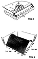
- Figure 3 is a perspective view of an embodiment of a vibration damper according to the prior art;
- Figure 4 illustrates the displacement profile of the surface of a tensioned mask subjected to vibrations;
- Figures 5 to 10 illustrate various embodiments of the invention.
- As illustrated in Figure 1, a cathode-ray tube 1 according to the invention comprises an approximately
plane panel 2 and a peripheral skirt 3. The panel is connected to the funnel-shaped rear part 4 of the tube by a glass-frit seal. The end part of the tube 5 surrounds the electron gun 6, the beams from which illuminate the screen ofluminescent phosphors 13 through thecolour selection mask 8, which in this case is plane, and for example tensioned between thelong sides 9 of theframe 19. Metal supports of the frame/mask assembly support this assembly inside the tube, the said supports possibly comprising apart 10 welded to the frame and a part forming aspring 11, which part is provided with an aperture for interacting with apin 12 included in the glass skirt 3. - In the example of the prior art illustrated by Figure 2, the
frame 19 comprises a pair oflong sides 9 and a pair of short sides 7, the said long and short sides having, for example, an L-shaped cross section. Themask 8, itself of approximately rectangular shape, is tensioned and then maintained in that state, for example by welding it to theend 20 of the said long sides of the frame. - The mask consists of a metal foil, for example made of steel or Invar, with a very small thickness of the order of 100 µm. The mask has a
central region 30, drilled with holes generally arranged in columns, and a peripheral region surrounding the central region withhorizontal edges 31 andvertical edges 32. - The cathode-ray tube structures using tensioned colour selection masks have to confront the problem of vibration of this mask, in modes which are natural modes of the said mask when the latter is excited by external vibrations, for example by mechanical shocks to the tube, or sound vibrations coming from loudspeakers placed near the tube. Since these vibrations result in movements of the mask in a direction perpendicular to its surface, the distance between the holes in the mask and the screen varies locally depending on the amplitude of the vibration of the said mask. The purity of the colours reproduced on the screen is therefore no longer guaranteed, the points of impingement of the beams on the screen being shifted depending on the amplitude of the vibration.
- Moreover, since the mask is placed inside the tube in which a high vacuum is created, the vibrations of the mask are damped only very slowly, the energy communicated to the mask having few means of dissipation, thereby increasing the visibility of the phenomenon on the screen when the tube is in operation.
- As illustrated in Figure 3, United States patent US 4,827,179 proposes a solution for damping the vibrations of the mask by means of a
device 41 forming a coupled oscillator, by placing along the edges of themask 8, near the region where the mask is welded to theframe 40, a mechanical structure having arigid support 42 to which at least oneflexible strip 43 is welded. The natural resonant frequency of thedevice 41 is chosen so as to damp the vibrations of the mask in a predetermined frequency band according to the principle of coupled oscillators. - However, this structure has a certain number of disadvantages:
- it is expensive since it requires additional
mechanical components and it complicates the process
for manufacturing the tube by adding a step, which is
that of fastening the
device 41 to one surface of the mask; - it is of limited use since the
device 41 can be used only near the region where the mask is welded to the frame, the frame reinforcing the solidity of the mask at this point; this is because most of the frame/mask structures are such that the mask is welded to the frame only at two parallel edges, for example thehorizontal edges 31; the free vertical edges are fragile because of the small thickness of the mask and the fastening of a device, such as anoscillator 41, can damage its surface, thus causing the frame/mask assembly thus produced to be rejected. - The invention provides a simple, inexpensive and easily implementable structure for damping the vibrations of a mask tensioned in one or two directions.
- Figure 5 illustrates a first embodiment of the invention.
- Cut in the surface of the peripheral part of the mask, for example along the short
vertical sides 32, is ametal strip 50 which remains linked to the mask at one of itsends 51 and is approximately parallel to the vertical direction of theshort side 32 of the mask. Thestrip 50 has a shape and an area designed so as to be able to vibrate in a direction approximately perpendicular to the surface of the mask, at a predetermined natural frequency, so as to damp the natural frequency of the mask in the frequency range which would be capable of exciting it. - In a second embodiment, illustrated in Figure 6, the strip intended to form a coupled oscillator is produced in such a way that its
end 61 for connection to the mask is approximately parallel to the horizontal direction of thelong sides 31 of the mask. One or both strips may be produced on eachshort side 32. If twometal strips 60 are placed on each short side, it is advantageous for thefree ends 65 of the strips to be arranged so as to face each other. It is possible to adjust the length 62 of the strip in order to bring the natural vibration frequency of the said strip to a predetermined value in order to damp the vibrations of theapertured part 30 of the mask. - In a third embodiment, illustrated in Figure 7, the
metal strip 70 intended to form an oscillator coupled with the mask is connected to the mask by aregion 71 approximately parallel to the short side of the mask, but extending in this direction over a shorter length than thestrip 70. Also in this case, twostrips 70 may be placed in such a way that theirfree ends 65 are arranged so as to face each other. - The shapes of the cut parts of the edges of the mask as well as the number of strips forming an oscillator are chosen so as to obtain the resonant frequency most appropriate to damping the vibrations of the mask.
- The mass of the strip is another criterion which determines its resonant frequency. It may be necessary to obtain a strip whose mass is greater than the maximum mass that can be obtained from the material of which the mask is composed.
- In this case, the mass of the
strip 60 can be increased by depositing acoating 90 on one or both faces of thestrip 60, as illustrated in Figure 9. This coating may advantageously be produced using inert materials, for example those based on glass-frit or on heavy metals, such as tungsten or molybdenum. - Also in the case in which it is desirable to increase the mass of the strip forming an oscillator, it is possible to position one or
more weights 100, as indicated in Figure 10, in order to adjust the resonant frequency of thestrip 60. These weights may be made of metal and fastened to thestrip 60 by welding. These weights may also be placed on any type of strip cut in the peripheral region of the mask, such as those illustrated in Figures 5 to 8. - The invention provides a structure allowing simple implementation of the means of dissipating the energy communicated to the mask upon an impact to the tube or via powerful sound waves. This is because the vibrations communicated to the mask, even if they are of low amplitude, must be prevented from lasting too long a time since they then become visible during the operation of the tube. Since the mask lies inside the tube in which a high vacuum is created, it is necessary to add energy-dissipation means so that the mask is rapidly damped. It is, for example, advantageous to add, to a
metal strip hole 80 made in the said strip. The hoop may be open or closed, the diameter of its cross section being slightly less than the diameter of thehole 80 so as to be able to move in this hole and dissipate the energy by friction against the edge of the said hole. As illustrated in Figure 8, the hoop 81 may advantageously pass through the facing two ends of twostrips 60 forming coupled oscillators, an arrangement allowing more rapid frictional dissipation with a single hoop 81. - In another embodiment (not illustrated), rivets are placed so as to pass through the metal strips, through
holes 80 made in the latter, the heads of the rivets being larger in size than the holes while the body of the rivet has a diameter smaller than the diameter of the said hole. - The arrangement of strips forming a coupled oscillator along the
short sides 32 of the mask is not limiting. It results, for example, from the choice of the value of the tension applied to the mask and from the aspect ratio of the mask, i.e. 4/3, 16/9, etc. - Figure 4 is a plot of the oscillation amplitudes of a mask for a tube whose screen has a 16/9 screen aspect ratio and a diagonal of 76 cm. The mask is tensioned in only one direction and is maintained under tension by being welded along the long sides of the
frame 19; moreover, it has a resonant frequency close to 100 Hz. In this figure, it may be seen that these oscillations have a maximum amplitude at the midpoint of the short vertical sides of the mask. The structure of the strips forming coupled oscillators is, in a preferred embodiment, tailored to these conditions, the one illustrated in Figure 6 with astrip 66 having a length of 34.7 mm, a width of 4 mm and a thickness of 0.2 mm. - For other mask tensions and other aspect ratios, the metal strips 50, 60, 70 could advantageously be placed along the long sides of the mask.
- Likewise, if the mask is tensioned in two directions parallel to its length and its width, it is advantageous to place vibration dampers according to the invention along both the horizontal and vertical sides of the said mask.
- The metal strips forming a coupled oscillator may be cut either by stamping, when cutting the outer edges of the mask, or by etching during the same manufacturing step as for producing the apertures in the apertured
central part 30. In both cases, there is no need for an additional step for producing thecut part 52. However, given the small thickness of the mask, etching may be more advantageous than stamping as it is mechanically less aggressive and is not limited in the shapes and sizes of the strips to be produced.
Claims (12)
- Colour cathode-ray tube comprising:the damping means being characterized in that they comprise at least one mechanical oscillator in the form of a metal strip (50, 60, 70) produced by partially cutting the surface of the peripheral region of the mask.a colour selection mask in the form of an approximately rectangular metal foil (8), designed to be fastened under tension to a support frame (19) and mounted inside the faceplate of the tube, the said mask having a central region (30) drilled with holes and a peripheral region (31, 32) lying between the central region and the edges of the mask, the said mask being capable of vibrating independently of the support frame,means for damping the vibrations of the mask, these means being placed around the said periphery of the mask in order to damp the vibrations of the said mask,
- Cathode-ray tube according to the preceding claim, characterized in that at least one mechanical oscillator is in the form of a metal strip, one end (65) of which is free to move in a plane perpendicular to the plane of the mask (8).
- Cathode-ray tube according to either of the preceding claims, characterized in that the mechanical oscillators are in the form of metal strips cut along the short sides (32) of the mask.
- Cathode-ray tube according to Claims 2 and 3, characterized in that the mask has, on each of its short sides, two mechanical oscillators (60, 70) in the form of parallel metal strips, the free ends (65) of which mechanical oscillators face each other.
- Cathode-ray tube according to one of the preceding claims, characterized in that the mechanical oscillators include friction-based energy-absorbing means (80, 81).
- Cathode-ray tube according to the preceding claim, characterized in that the friction-based energy-absorbing means comprise a hoop (81) passing through a hole (80) made through a strip (50, 60, 70) forming a mechanical oscillator.
- Cathode-ray tube according to Claims 4 and 6, characterized in that the hoop links the two free ends of the mechanical oscillators (60, 70) facing each other.
- Cathode-ray tube according to one of the preceding claims, characterized in that all or part of a face of a metal strip forming a mechanical oscillator is covered with a coating (90) so as to bring its resonant frequency to a predetermined value.
- Cathode-ray tube according to the preceding claim, characterized in that the coating consists of a metal layer comprising a heavy metal.
- Cathode-ray tube according to one of the preceding claims, characterized in that at least one weight (100) is placed on one face of a metal strip (50, 60, 70) forming a mechanical oscillator so as to bring its resonant frequency to a predetermined value.
- Cathode-ray tube according to one of the preceding claims, characterized in that the metal strips forming mechanical oscillators are produced by etching the metal foil of which the mask is composed.
- Cathode-ray tube according to the preceding claim, characterized in that the strips forming mechanical oscillators are etched at the same time as the holes in the central region of the mask.
Applications Claiming Priority (2)
| Application Number | Priority Date | Filing Date | Title |
|---|---|---|---|
| IT1999MI001992A IT1313721B1 (en) | 1999-09-24 | 1999-09-24 | COLOR SELECTION MASK FOR TUBE WITH DEAD-BEAMS |
| ITMI991992 | 1999-09-24 |
Publications (3)
| Publication Number | Publication Date |
|---|---|
| EP1087418A1 true EP1087418A1 (en) | 2001-03-28 |
| EP1087418B1 EP1087418B1 (en) | 2005-11-16 |
| EP1087418B8 EP1087418B8 (en) | 2006-02-01 |
Family
ID=11383657
Family Applications (1)
| Application Number | Title | Priority Date | Filing Date |
|---|---|---|---|
| EP00120729A Expired - Lifetime EP1087418B8 (en) | 1999-09-24 | 2000-09-22 | Colour selection mask for cathode ray tube |
Country Status (10)
| Country | Link |
|---|---|
| US (1) | US6469429B1 (en) |
| EP (1) | EP1087418B8 (en) |
| JP (1) | JP3898883B2 (en) |
| KR (1) | KR100762755B1 (en) |
| CN (1) | CN1229841C (en) |
| DE (1) | DE60024026T2 (en) |
| IT (1) | IT1313721B1 (en) |
| MX (1) | MXPA00009317A (en) |
| MY (1) | MY120094A (en) |
| TW (1) | TW478000B (en) |
Cited By (3)
| Publication number | Priority date | Publication date | Assignee | Title |
|---|---|---|---|---|
| WO2002009138A1 (en) * | 2000-07-25 | 2002-01-31 | Koninklijke Philips Electronics N.V. | Display tube comprising a mask with vibration damping means |
| WO2003023811A1 (en) * | 2001-09-07 | 2003-03-20 | Thomson Licensing S.A. | Crt having vibration damping system |
| EP1288995A3 (en) * | 2001-08-29 | 2004-12-01 | LG Philips Displays Korea Co., Ltd. | Dynamic vibration absorber for cathode ray tube |
Families Citing this family (6)
| Publication number | Priority date | Publication date | Assignee | Title |
|---|---|---|---|---|
| JP3300669B2 (en) * | 1998-09-01 | 2002-07-08 | 松下電器産業株式会社 | Color cathode ray tube |
| IT1313924B1 (en) * | 1999-11-05 | 2002-09-26 | Videocolor Spa | STRUCTURE OF FRAME / MASK PERFECTED FOR TUBE WITH CATHODE RAYS. |
| IT1319319B1 (en) * | 2000-11-07 | 2003-10-10 | Videocolor Spa | COLOR CATHODE TUBE AND MORE IN PARTICULAR A MASK STRUCTURE ADAPTED TO BE MAINTAINED IN VOLTAGE INSIDE THE |
| US6936957B2 (en) * | 2001-07-12 | 2005-08-30 | Lg Electronics, Inc. | Anti-howling device in cathode ray tube |
| US6710531B2 (en) * | 2001-12-21 | 2004-03-23 | Thomson Licensing S.A. | CRT having a shadow mask vibration damper |
| ITMI20021251A1 (en) | 2002-06-07 | 2003-12-09 | Videocolor Spa | VIBRATION DAMPING DEVICE FOR FRAME / MASK DITUBE CATHODE |
Citations (2)
| Publication number | Priority date | Publication date | Assignee | Title |
|---|---|---|---|---|
| US4827179A (en) * | 1987-06-09 | 1989-05-02 | Zenith Electronics Corporation | Mask vibration damping in cathode ray tubes |
| JP2000048736A (en) * | 1998-05-28 | 2000-02-18 | Sony Corp | Color selection mechanism and color cathode ray tube receiver |
Family Cites Families (3)
| Publication number | Priority date | Publication date | Assignee | Title |
|---|---|---|---|---|
| US5451833A (en) * | 1993-10-28 | 1995-09-19 | Chunghwa Picture Tubes, Ltd. | Shadow mask damping for color CRT |
| JP3300669B2 (en) | 1998-09-01 | 2002-07-08 | 松下電器産業株式会社 | Color cathode ray tube |
| KR100385214B1 (en) * | 1999-12-09 | 2003-05-27 | 삼성에스디아이 주식회사 | Tension mask frame assembly of the flat CRT |
-
1999
- 1999-09-24 IT IT1999MI001992A patent/IT1313721B1/en active
-
2000
- 2000-07-18 TW TW089114345A patent/TW478000B/en not_active IP Right Cessation
- 2000-09-22 KR KR1020000055744A patent/KR100762755B1/en not_active Expired - Fee Related
- 2000-09-22 JP JP2000289105A patent/JP3898883B2/en not_active Expired - Fee Related
- 2000-09-22 EP EP00120729A patent/EP1087418B8/en not_active Expired - Lifetime
- 2000-09-22 MY MYPI20004429A patent/MY120094A/en unknown
- 2000-09-22 DE DE60024026T patent/DE60024026T2/en not_active Expired - Fee Related
- 2000-09-22 MX MXPA00009317A patent/MXPA00009317A/en unknown
- 2000-09-22 US US09/667,479 patent/US6469429B1/en not_active Expired - Fee Related
- 2000-09-24 CN CNB001313991A patent/CN1229841C/en not_active Expired - Fee Related
Patent Citations (2)
| Publication number | Priority date | Publication date | Assignee | Title |
|---|---|---|---|---|
| US4827179A (en) * | 1987-06-09 | 1989-05-02 | Zenith Electronics Corporation | Mask vibration damping in cathode ray tubes |
| JP2000048736A (en) * | 1998-05-28 | 2000-02-18 | Sony Corp | Color selection mechanism and color cathode ray tube receiver |
Non-Patent Citations (1)
| Title |
|---|
| PATENT ABSTRACTS OF JAPAN vol. 2000, no. 05 14 September 2000 (2000-09-14) * |
Cited By (6)
| Publication number | Priority date | Publication date | Assignee | Title |
|---|---|---|---|---|
| WO2002009138A1 (en) * | 2000-07-25 | 2002-01-31 | Koninklijke Philips Electronics N.V. | Display tube comprising a mask with vibration damping means |
| US6646369B2 (en) | 2000-07-25 | 2003-11-11 | Koninklijke Philips Electronics N.V. | Display tube comprising a mask with vibration damping means |
| EP1288995A3 (en) * | 2001-08-29 | 2004-12-01 | LG Philips Displays Korea Co., Ltd. | Dynamic vibration absorber for cathode ray tube |
| US6914375B2 (en) | 2001-08-29 | 2005-07-05 | Lg. Philips Displays Korea Co., Ltd. | Dynamic vibration absorber in cathode ray tube |
| WO2003023811A1 (en) * | 2001-09-07 | 2003-03-20 | Thomson Licensing S.A. | Crt having vibration damping system |
| US7091655B2 (en) | 2001-09-07 | 2006-08-15 | Thomson Licensing | CRT vibration damping system |
Also Published As
| Publication number | Publication date |
|---|---|
| ITMI991992A0 (en) | 1999-09-24 |
| KR100762755B1 (en) | 2007-10-09 |
| IT1313721B1 (en) | 2002-09-17 |
| KR20010039910A (en) | 2001-05-15 |
| EP1087418B1 (en) | 2005-11-16 |
| CN1229841C (en) | 2005-11-30 |
| DE60024026T2 (en) | 2006-07-27 |
| ITMI991992A1 (en) | 2001-03-24 |
| CN1290022A (en) | 2001-04-04 |
| MY120094A (en) | 2005-08-30 |
| US6469429B1 (en) | 2002-10-22 |
| DE60024026D1 (en) | 2005-12-22 |
| EP1087418B8 (en) | 2006-02-01 |
| MXPA00009317A (en) | 2002-10-23 |
| TW478000B (en) | 2002-03-01 |
| JP3898883B2 (en) | 2007-03-28 |
| JP2001135256A (en) | 2001-05-18 |
Similar Documents
| Publication | Publication Date | Title |
|---|---|---|
| EP1087418B1 (en) | Colour selection mask for cathode ray tube | |
| US6614152B1 (en) | Frame/mask structure for cathode ray tube | |
| US5289080A (en) | Mask frame damper for color cathode ray tubes | |
| US6900582B2 (en) | CRT having a tension mask with vibration damping mean | |
| US7091655B2 (en) | CRT vibration damping system | |
| CN1316541C (en) | CRT having a shadow mask vibration damper | |
| EP1372181B1 (en) | Vibration absorber device for colour cathode-ray tube | |
| WO2006044269A1 (en) | Damper for a cathode-ray tube (crt) tension mask | |
| WO2006044326A1 (en) | Damper for a cathode-ray tube (crt) tension mask | |
| KR20060008969A (en) | Shockproof device for cathode ray tube frame / mask set | |
| US20020180330A1 (en) | Mask assembly for cathode ray tube | |
| KR19990000044A (en) | Vibration Damping Device for Flat Tension Mask | |
| EP1430505A2 (en) | Color display tube with improved color selection electrode | |
| KR20030093487A (en) | Tension mask assembly | |
| KR20040080532A (en) | Tension mask -frame asseambly for color cathode ray tube | |
| KR20010104514A (en) | Tension mask frame assembly of CRT |
Legal Events
| Date | Code | Title | Description |
|---|---|---|---|
| PUAI | Public reference made under article 153(3) epc to a published international application that has entered the european phase |
Free format text: ORIGINAL CODE: 0009012 |
|
| AK | Designated contracting states |
Kind code of ref document: A1 Designated state(s): DE FR GB IT |
|
| AX | Request for extension of the european patent |
Free format text: AL;LT;LV;MK;RO;SI |
|
| 17P | Request for examination filed |
Effective date: 20010903 |
|
| AKX | Designation fees paid |
Free format text: DE FR GB IT |
|
| GRAP | Despatch of communication of intention to grant a patent |
Free format text: ORIGINAL CODE: EPIDOSNIGR1 |
|
| GRAS | Grant fee paid |
Free format text: ORIGINAL CODE: EPIDOSNIGR3 |
|
| GRAA | (expected) grant |
Free format text: ORIGINAL CODE: 0009210 |
|
| AK | Designated contracting states |
Kind code of ref document: B1 Designated state(s): DE FR GB IT |
|
| REG | Reference to a national code |
Ref country code: GB Ref legal event code: FG4D |
|
| RAP2 | Party data changed (patent owner data changed or rights of a patent transferred) |
Owner name: THOMSON LICENSING |
|
| REF | Corresponds to: |
Ref document number: 60024026 Country of ref document: DE Date of ref document: 20051222 Kind code of ref document: P |
|
| ET | Fr: translation filed | ||
| PLBE | No opposition filed within time limit |
Free format text: ORIGINAL CODE: 0009261 |
|
| STAA | Information on the status of an ep patent application or granted ep patent |
Free format text: STATUS: NO OPPOSITION FILED WITHIN TIME LIMIT |
|
| 26N | No opposition filed |
Effective date: 20060817 |
|
| PGFP | Annual fee paid to national office [announced via postgrant information from national office to epo] |
Ref country code: IT Payment date: 20080926 Year of fee payment: 9 |
|
| PGFP | Annual fee paid to national office [announced via postgrant information from national office to epo] |
Ref country code: GB Payment date: 20080828 Year of fee payment: 9 |
|
| PGFP | Annual fee paid to national office [announced via postgrant information from national office to epo] |
Ref country code: DE Payment date: 20080924 Year of fee payment: 9 |
|
| PGFP | Annual fee paid to national office [announced via postgrant information from national office to epo] |
Ref country code: FR Payment date: 20091021 Year of fee payment: 10 |
|
| GBPC | Gb: european patent ceased through non-payment of renewal fee |
Effective date: 20090922 |
|
| PG25 | Lapsed in a contracting state [announced via postgrant information from national office to epo] |
Ref country code: DE Free format text: LAPSE BECAUSE OF NON-PAYMENT OF DUE FEES Effective date: 20100401 |
|
| PG25 | Lapsed in a contracting state [announced via postgrant information from national office to epo] |
Ref country code: GB Free format text: LAPSE BECAUSE OF NON-PAYMENT OF DUE FEES Effective date: 20090922 |
|
| PG25 | Lapsed in a contracting state [announced via postgrant information from national office to epo] |
Ref country code: IT Free format text: LAPSE BECAUSE OF NON-PAYMENT OF DUE FEES Effective date: 20090922 |
|
| REG | Reference to a national code |
Ref country code: FR Ref legal event code: ST Effective date: 20110531 |
|
| PG25 | Lapsed in a contracting state [announced via postgrant information from national office to epo] |
Ref country code: FR Free format text: LAPSE BECAUSE OF NON-PAYMENT OF DUE FEES Effective date: 20100930 |