EP1087335A2 - Stereoscopic image processing apparatus and method - Google Patents
Stereoscopic image processing apparatus and method Download PDFInfo
- Publication number
- EP1087335A2 EP1087335A2 EP00119922A EP00119922A EP1087335A2 EP 1087335 A2 EP1087335 A2 EP 1087335A2 EP 00119922 A EP00119922 A EP 00119922A EP 00119922 A EP00119922 A EP 00119922A EP 1087335 A2 EP1087335 A2 EP 1087335A2
- Authority
- EP
- European Patent Office
- Prior art keywords
- parallax
- photographed image
- parallaxes
- pixel block
- image
- Prior art date
- Legal status (The legal status is an assumption and is not a legal conclusion. Google has not performed a legal analysis and makes no representation as to the accuracy of the status listed.)
- Granted
Links
Images



Classifications
-
- G—PHYSICS
- G06—COMPUTING OR CALCULATING; COUNTING
- G06T—IMAGE DATA PROCESSING OR GENERATION, IN GENERAL
- G06T7/00—Image analysis
- G06T7/50—Depth or shape recovery
- G06T7/55—Depth or shape recovery from multiple images
- G06T7/593—Depth or shape recovery from multiple images from stereo images
Definitions
- the present invention relates to an apparatus and a method for stereoscopic image processing. More particularly, it is concerned with a process of filtering parallaxes calculated from stereoscopic images.
- a vehicle monitoring apparatus which obtains information (preview information) on views ahead of own vehicle using a stereo camera apparatus and controls the vehicle based on this information.
- a stereo type vehicle monitoring apparatus calculates a positional deviation (parallax) of a common object on a pair of photographed images (stereo matching).
- the apparatus determines the distance to the object based on the calculated parallax using the principle of triangulation.
- the apparatus recognizes the distance to a running vehicle or other objects ahead of own vehicle or road shapes.
- an object of the present invention is to provide an apparatus and a method for stereoscopic image processing which remove wrong parallaxes by filtering operation if the wrong parallaxes have been calculated due to a mismatch in the stereo matching under such conditions that a plurality of look-alike three-dimensional objects are present.
- Another object of the present invention is to prevent deterioration of reliability of distance information by removing erroneously calculated parallaxes.
- a stereoscopic image processing apparatus comprising: a first image producing unit; a second image producing unit; a stereo matching unit; and a filter.
- the first image producing unit produces a first photographed image of an object scene.
- the second image producing unit produces a second photographed image of the object scene.
- the stereo matching unit identifies within the second photographed image a correlated destination of each pixel block in first photographed image by searching along the same horizontal line as the pixel block of the first photographed image and calculates a parallax of the pixel block based on a deviation between a position of the pixel block of the first photographed image and a position of the correlated destination.
- the filter judges the smallest parallax in the parallaxes of the plural pixel blocks as a valid parallax when plural pixel blocks located on the same horizontal line in the first photographed image have the same correlated destination in the second photographed image.
- the filter judges the parallax, which has not been judged as the valid parallax, as valid parallax, if it has a value smaller than a predetermined value.
- a stereoscopic image processing method comprising:
- the step of judging the parallax having the smallest value judges the parallax, which has not been judged as the valid parallax, as a valid parallax if it has a value smaller than a predetermined value.
- the stereoscopic image processing method of the invention preferably further comprises: counting the number of parallaxes which have not been judged as the valid parallax.
- a stereoscopic image processing apparatus comprising: a first image producing unit; a second image producing unit; a stereo matching unit; and a filter.
- the first image producing unit produces a first photographed image of an object scene.
- the second image producing unit produces a second photographed image of the object scene.
- the stereo matching unit identifies within the second photographed image a correlated destination of each pixel block in first photographed image by searching along the same horizontal line as the pixel block of the first photographed image and calculates a parallax of the pixel block based on a deviation between a position of the pixel block of the first photographed image and a position of the correlated destination.
- the filter judges parallaxes each of which has a value smaller than a predetermined value as valid parallaxes, when plural pixel blocks located on the same horizontal line in the first photographed image have the same correlated destination in the second photographed image.
- the filter judges the smallest parallax in the parallaxes, which have been judged as the valid parallaxes, as a valid parallax.
- Fig. 1 is a block diagram of a stereo type vehicle monitoring apparatus.
- a stereo camera apparatus 1 takes pictures of views outside of a vehicle.
- the stereo camera apparatus 1 is mounted in the vicinity of its rear-view mirror and formed of a pair of cameras 2a, 2b, each incorporating an image sensor such as a charge-coupled device (CCD).
- CCD charge-coupled device
- These cameras 2a, 2b are attached with a predetermined spacing in a direction of vehicle width therebetween.
- the main camera 2a for obtaining a reference image is attached on the right side of a vehicle's forward direction.
- the sub-camera 2b for obtaining a comparative image is attached on the left side of the forward direction.
- analog images output from the individual cameras 2a, 2b are adjusted in analog interfaces 3 such that the analog images match input ranges of succeeding stages.
- Gain control amplifiers (GCA's) in the individual analog interfaces 3 adjust brightness balance of a pair of analog image signals.
- the pair of the analog images adjusted in the analog interfaces 3 is converted into digital images of a predetermined brightness level(e.g., 256 gray scale levels) by analog-to-digital (A/D) converters 4.
- the digitized image pair (stereoscopic images) is subjected to a brightness correction and a geometric transformation, for instance, which are performed by a correction circuit 5. Since there are usually more or less some errors in mounting positions of the stereo cameras 2a, 2b, there exists a displacement of the left and right images caused by those errors. Thus, the geometric transformation, such as rotation or parallel displacement of the images, is performed using an affine transformation, for example. Such treatment ensures a precondition for performing stereo matching that horizontal lines of the pair of images should coincide with each other.
- reference image data of 512 pixels in the horizontal direction by 200 pixels in the vertical direction is produced from an output signal of the main camera 2a. Also, from an output signal of the sub-camera 2b, comparative image data having the same vertical length as the reference image data and a greater horizontal length than the reference image data (640 pixels in the horizontal direction by 200 pixels in the vertical direction, for example) is obtained.
- the reference image data and the comparative image data are stored in an image data memory 7.
- a stereo processing circuit 6 calculates parallaxes based on the reference image data and the comparative image data. Since the parallax is calculated for each individual pixel block of 4 ⁇ 4 pixels, a maximum of 128 ⁇ 50 parallaxes can be obtained from one complete frame of the reference image. Considering one pixel block in the reference image, a region having a correlation with brightness property of the pixel block in the reference image is identified by searching within the comparative image (stereo matching).
- the distance to a photographed object is obtained as a parallax in the stereoscopic images, that is, as the amount of deviation in a horizontal direction between the reference image and the comparative image. Therefore, when searching for the comparative image, search is to be made on the same horizontal line (epipolar line) as the horizontal position (j-coordinate) of the relevant pixel block in the reference image. While shifting a search point pixel by pixel along the epipolar line, the stereo processing circuit 6 evaluates the correlation between the individual pixel blocks in the comparative image and the relevant pixel block in the reference image. The correlation between the pixel blocks can be evaluated by calculating city block distances, for example.
- a pixel block where the value of the city block distance is a minimum is the pixel block having a correlation.
- Parallaxes between the pixel blocks are output as parallaxes.
- the parallaxes for one frame calculated by the aforementioned method are stored in a distance data memory 8.
- a microcomputer 9 (or a recognizing section 10 which is a functional block of the microcomputer 9 when viewed from a functional point of view) recognizes road shapes (white lines) and each three-dimensional object (running vehicle) ahead of own vehicle, for example. This recognition is made based on the image data stored in the image data memory 7 and the parallaxes stored in the distance data memory 8. Sensor information fed from a vehicle speed sensor and a steering angle sensor, which are not illustrated, as well as navigation information is also referred to as necessary. Reference should be made to Japanese Unexamined Patent Publication No. 5-265547 for specific methods of recognition of road shapes and three-dimensional objects, if necessary, since they are disclosed therein.
- the microcomputer 9 activates a warning unit 11, such as a monitor or a speaker, to thereby draw a driver's attention. Also, the microcomputer 9 performs such vehicle control operation as a downshift of an AT (automatic transmission), a reduction in engine output, or activation of brakes by controlling a control unit 12 as the need arises.
- a warning unit 11 such as a monitor or a speaker
- a pairing filter 13 detects a discordance in positional relationship between pixel blocks which have been judged by the stereo processing circuit 6 to have a correlation, and removes the parallax calculated for such pixel blocks having the discordance. Specifically, when multiple pixel blocks PB1, PB2 on the same horizontal line in the reference image have a common correlated destination (pixel block PB3) as shown in Fig. 2, the parallax of only one pixel block is judged to be a valid parallax, and this valid parallax is transferred to the recognizing section 10. The rest is judged to be an invalid parallax (the parallax is set to be 0).
- plural pixel blocks located on the same horizontal line in the reference image would not have a common correlated destination.
- the plural pixel blocks PB1, PB2 may be accidentally matched with the same pixel block PB3. This will result calculation of a wrong parallax.
- the pairing filter 13 selects only the smallest parallax (parallax of the pixel block PB2) as the valid one and regards the other parallax (parallax of the pixel block PB1) as being invalid. This means that priority is given to distance information on a distant object rather than to distance information on a nearby object.
- a reason why the priority is given to a smaller parallax is that an object existing at a long distance appears small in a photographed image and, as a consequence, the number of parallaxes calculated for the distant object is small.
- an object existing at a short distance appears relatively large, there is a tendency that a relatively large number of parallaxes are calculated for that nearby object. Therefore, even if some parallaxes are invalidated by filtering operation, the number of distance data of the nearby object rarely becomes insufficient. On the contrary, since the object at the long distance appears small when photographed, the number of parallaxes calculated for this distant object is not so large.
- parallaxes of the object at the long distance are made invalid, it is likely that the amount of information on the distant object becomes insufficient. Consequently, the importance of the individual parallaxes inevitably becomes greater for distant objects than for nearby objects. For the aforementioned reasons, smaller parallaxes are judged to be valid and the remaining parallaxes whose importance is considered to be less significant are judged to be invalid.
- the pairing filter 13 By using the above-described pairing filter 13, it is possible to properly remove parallaxes erroneously calculated due to a mismatch in the stereo matching even under such conditions that a plurality of look-alike objects are present. In other words, as a result of performing the filtering operation, it is possible to make corrections in such a way that plural pixel blocks in the reference image would not be related to the same region in the comparative image (to avoid a plural-to-one correlation). Accordingly, the accuracy of parallaxes which have been judged to be valid in the filtering operation by the pairing filter 13 is higher than the accuracy of parallaxes calculated by the stereo processing circuit 6.
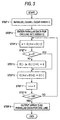
- Fig. 3 is a flowchart showing a procedure of the filtering operation.
- Figs. 4A-C are diagrams for explaining corrections to be made to parallaxes for one line.
- initialization is carried out in step 1. Specifically, a counter i is reset to 0 and an array C is cleared.
- the array C is a work area for evaluating correlations of parallaxes calculated for one horizontal line of pixel blocks in the reference image and is formed of the same number of array elements C[0] to C[639] as the number of pixels horizontally arranged in the comparative image.
- parallax data for one horizontal line are taken into an array D .
- the array D is formed of the same number of array elements D[0] to D[127] as the number of pixel blocks horizontally arranged in the reference image.
- the parallax of array element D[0] is 8.
- the individual array elements D[i] (0 ⁇ i ⁇ 127) correspond to the pixel blocks and the number of pixels horizontally arranged in each pixel block is 4. Therefore, the correlated destination of array element D[0] is array element C[8] (0 ⁇ 4+8).
- the parallax 8 of array element D[0] is invalidated by a sequence of steps 3 to 9 described below.
- step 3 variable e is set to the value of array element C[4 ⁇ i+D[i]] . Since the initial value of i is 0 and array element D[0] is 8, e is set to 0.
- step 4 a judgment is made as to whether the variable e is equal to 0 or not. Since e is equal to 0, the operation flow proceeds to step 6, in which the value of array element D[i] is set in array element C[4 ⁇ i+D[i]] .
- the value of array element D[0], or 8 is set in array element C[8] as shown in Fig. 4B.
- the fact that a value is set in an array element C[j] (0 ⁇ j ⁇ 639) means that there exists an array element D[i] whose correlated destination is the array element C[j].
- step 6 which follows step 7, after the counter i has been incremented (that is, i has become equal to 1), a judgment is made as to whether the value of the counter i is equal to 128, or as to whether evaluation of one horizontal line of the reference image has been finished. Since i is equal to 1, the operation flow returns to step 3.
- step 3 the value of array element C[4 ⁇ 1+D[1]] , or 8, is read out and the variable e is set to 8.
- the operation flow proceeds to step 5 after a negative judgment in step 4, and the value of an array element having a larger parallax is set to 0.
- the value of array element D[i-(e-D[i])/4] is set to 0.
- step 6 the array element D[1] is set to the array element C[4 ⁇ 1+D[1]] , or C[8].
- step 9 the corrected array D is output as parallax data for one line and the operation is finished.
- the filtering operation shown in the flowchart of Fig. 3 is performed on all horizontal lines (50 lines) in one complete frame in the above-described manner.
- the number of parallaxes removed by the pairing filter 13 (the number of parallaxes which have been judged to be invalid)is large, it means that there is a problem in the reliability of the parallaxes calculated by the stereo processing circuit 6.
- the number of invalidated parallaxes in the pairing filter 13 is counted to obtain the number of invalidated parallaxes for one line (or for one frame). If this number is used as a reliability factor, it is possible to perform more proper vehicle monitoring control operation. It would also be possible to take a method to weight the parallax data in the recognizing section 10 based on the reliability factor.
- the array C which is the work area for evaluating the parallaxes needs to include 640 array element C[j]. If, however, steps 3, 5 and 6 are modified as shown below, it is possible to reduce the size of the work area to 1/4.
- the array C of this case is formed of i number of array element C[i] (0 ⁇ i ⁇ 160).
- parallaxes When incorrect parallaxes have been calculated due to a mismatch in stereo matching under conditions where a plurality of similar-looking three-dimensional objects exist, it is possible to remove such parallaxes by filtering operation as seen above in the present invention. Then, it is possible to prevent deterioration of reliability of distance information (parallaxes) by removing the erroneously calculated parallaxes.
Landscapes
- Engineering & Computer Science (AREA)
- Computer Vision & Pattern Recognition (AREA)
- Physics & Mathematics (AREA)
- General Physics & Mathematics (AREA)
- Theoretical Computer Science (AREA)
- Image Processing (AREA)
- Measurement Of Optical Distance (AREA)
- Image Analysis (AREA)
- Testing, Inspecting, Measuring Of Stereoscopic Televisions And Televisions (AREA)
- Length Measuring Devices By Optical Means (AREA)
Abstract
Description
Claims (7)
- A stereoscopic image processing apparatus,
comprising:a first image producing unit (2a) which produces a first photographed image of an object scene;a second image producing unit (2b) which produces a second photographed image of the object scene;a stereo matching unit (6, 8, 13) which is adapted to identify within the second photographed image a correlated destination of each pixel block (PB) in the first photographed image by searching along the same horizontal line as the pixel block (PB) of the first photographed image and to calculate a parallax of the pixel block (PB) based on a deviation between a position of the pixel block of the first photographed image and a position of the correlated destination; anda filter (13) which, when a plurality of pixel blocks (PB) located on the same horizontal line in the first photographed image have the same correlated destination in the second photographed image, is adapted to judge the smallest parallax in the parallaxes of the plurality of pixel blocks (PB) as a valid parallax. - The apparatus according to claim 1,
wherein the filter (13) is adapted to judge the parallax, which has not been judged as the valid parallax, as the valid parallax, if it has a value smaller than a predetermined value. - A stereoscopic image processing apparatus,
comprising:a first image producing unit (2a) which produces a first photographed image of an object scene;a second image producing unit (2b) which produces a second photographed image of the object scene;a stereo matching unit (6, 8, 13) which is adapted to identify within the second photographed image a correlated destination of each pixel block (PB) in the first photographed image by searching along the same horizontal line as the pixel block (PB) of the first photographed image and to calculate a parallax of the pixel block (PB) based on a deviation between a position of the pixel block (PB) of the first photographed image and a position of the correlated destination; anda filter (13) which, when a plurality of pixel blocks (PB) located on the same horizontal line in the first photographed image have the same correlated destination in the second photographed image, is adapted to judge parallaxes each of which has a value smaller than a predetermined value as valid parallaxes. - The apparatus according to claim 3,
wherein the filter (13) is adapted to judge the smallest parallax in the parallaxes, which have been judged as the valid parallaxes, as a valid parallax. - A stereoscopic image processing method,
comprising the following steps:producing a first photographed image (2a) of an object scene;producing a second photographed image (2b) of the object scene;identifying within the second photographed image a correlated destination of each pixel block (PB) in the first photographed image by searching along the same horizontal line as the pixel block (PB) of the first photographed image;calculating a parallax of the pixel block (PB) based on a deviation between a position of the pixel block (PB) of the first photographed image and a position of the correlated destination; andjudging, when a plurality of pixel blocks (PB) located on the same horizontal line in the first photographed image have the same correlated destination in the second photographed image, the smallest parallax in the parallaxes of the plurality of pixel blocks (PB) as a valid parallax. - The method according to claim 5,
wherein the step of judging the parallax having the smallest value judges the parallax, which has not been judged as the valid parallax, as a valid parallax if it has a value smaller than a predetermined value. - The method according to claim 5 or 6,
further comprising the step ofcounting the number of parallaxes which have not been judged as the valid parallax.
Applications Claiming Priority (2)
| Application Number | Priority Date | Filing Date | Title |
|---|---|---|---|
| JP26939699 | 1999-09-22 | ||
| JP26939699A JP3287465B2 (en) | 1999-09-22 | 1999-09-22 | Stereo image processing device |
Publications (3)
| Publication Number | Publication Date |
|---|---|
| EP1087335A2 true EP1087335A2 (en) | 2001-03-28 |
| EP1087335A3 EP1087335A3 (en) | 2006-05-24 |
| EP1087335B1 EP1087335B1 (en) | 2015-09-02 |
Family
ID=17471835
Family Applications (1)
| Application Number | Title | Priority Date | Filing Date |
|---|---|---|---|
| EP00119922.3A Expired - Lifetime EP1087335B1 (en) | 1999-09-22 | 2000-09-13 | Stereoscopic image processing apparatus and method |
Country Status (3)
| Country | Link |
|---|---|
| US (1) | US6366691B1 (en) |
| EP (1) | EP1087335B1 (en) |
| JP (1) | JP3287465B2 (en) |
Cited By (1)
| Publication number | Priority date | Publication date | Assignee | Title |
|---|---|---|---|---|
| EP1298013A3 (en) * | 2001-09-27 | 2004-09-08 | Kabushiki Kaisha Tokai Rika Denki Seisakusho | Passenger compartment monitoring apparatus |
Families Citing this family (19)
| Publication number | Priority date | Publication date | Assignee | Title |
|---|---|---|---|---|
| EP1138574A3 (en) | 2000-03-30 | 2004-03-24 | Nihon Plast Co., Ltd. | Core bar for steering wheels |
| JP3925488B2 (en) * | 2003-11-11 | 2007-06-06 | 日産自動車株式会社 | Image processing apparatus for vehicle |
| JP2006005608A (en) * | 2004-06-17 | 2006-01-05 | Hitachi Ltd | Imaging device |
| US7660432B2 (en) * | 2004-10-21 | 2010-02-09 | Kazunari Era | Method for controlling creation of stereoscopic image |
| KR100834637B1 (en) * | 2006-11-27 | 2008-06-02 | 삼성전자주식회사 | Apparatus and method for aligning images in a stereo camera device |
| US7865285B2 (en) * | 2006-12-27 | 2011-01-04 | Caterpillar Inc | Machine control system and method |
| CA2692277A1 (en) * | 2007-07-03 | 2009-01-08 | J. Edward Ramsey | Trailer hitch alignment device and method |
| JP4856612B2 (en) * | 2007-10-29 | 2012-01-18 | 富士重工業株式会社 | Object detection device |
| JP4958302B2 (en) * | 2007-12-12 | 2012-06-20 | 独立行政法人情報通信研究機構 | Multi-viewpoint image depth value extraction apparatus, method and program thereof |
| JP4886716B2 (en) * | 2008-02-26 | 2012-02-29 | 富士フイルム株式会社 | Image processing apparatus and method, and program |
| CN102197276A (en) * | 2008-10-28 | 2011-09-21 | 株式会社博思科 | Road measurement device and method for measuring road |
| US8731277B2 (en) | 2011-01-26 | 2014-05-20 | Aptina Imaging Corporation | Methods for matching gain and color for stereoscopic imaging systems |
| US9076215B2 (en) * | 2011-11-28 | 2015-07-07 | Panasonic Intellectual Property Management Co., Ltd. | Arithmetic processing device |
| JP5890816B2 (en) | 2013-09-30 | 2016-03-22 | 富士重工業株式会社 | Filtering device and environment recognition system |
| JP5955292B2 (en) | 2013-09-30 | 2016-07-20 | 富士重工業株式会社 | Filtering device |
| JP6329442B2 (en) * | 2014-06-26 | 2018-05-23 | 株式会社Subaru | Outside environment recognition device |
| CN105701262A (en) * | 2014-11-26 | 2016-06-22 | 英业达科技有限公司 | Three-dimensional model part comparison system and method |
| JP6805534B2 (en) | 2015-07-02 | 2020-12-23 | 株式会社リコー | Parallax image generator, parallax image generation method and parallax image generation program, object recognition device, device control system |
| JPWO2023136050A1 (en) * | 2022-01-14 | 2023-07-20 |
Family Cites Families (6)
| Publication number | Priority date | Publication date | Assignee | Title |
|---|---|---|---|---|
| JP3167752B2 (en) | 1991-10-22 | 2001-05-21 | 富士重工業株式会社 | Vehicle distance detection device |
| JPH05265547A (en) | 1992-03-23 | 1993-10-15 | Fuji Heavy Ind Ltd | On-vehicle outside monitoring device |
| US5581638A (en) * | 1993-07-26 | 1996-12-03 | E-Systems, Inc. | Method for autonomous image registration |
| TW282527B (en) * | 1994-11-11 | 1996-08-01 | Nintendo Co Ltd | |
| DE19636028C1 (en) * | 1996-09-05 | 1997-11-20 | Daimler Benz Ag | Stereo image object detection, esp. for road vehicles |
| GB9707554D0 (en) * | 1997-04-15 | 1997-06-04 | Aea Technology Plc | Control apparatus and method |
-
1999
- 1999-09-22 JP JP26939699A patent/JP3287465B2/en not_active Expired - Lifetime
-
2000
- 2000-09-13 EP EP00119922.3A patent/EP1087335B1/en not_active Expired - Lifetime
- 2000-09-21 US US09/667,005 patent/US6366691B1/en not_active Expired - Lifetime
Cited By (1)
| Publication number | Priority date | Publication date | Assignee | Title |
|---|---|---|---|---|
| EP1298013A3 (en) * | 2001-09-27 | 2004-09-08 | Kabushiki Kaisha Tokai Rika Denki Seisakusho | Passenger compartment monitoring apparatus |
Also Published As
| Publication number | Publication date |
|---|---|
| EP1087335B1 (en) | 2015-09-02 |
| JP2001092969A (en) | 2001-04-06 |
| US6366691B1 (en) | 2002-04-02 |
| EP1087335A3 (en) | 2006-05-24 |
| JP3287465B2 (en) | 2002-06-04 |
Similar Documents
| Publication | Publication Date | Title |
|---|---|---|
| US6366691B1 (en) | Stereoscopic image processing apparatus and method | |
| US7092015B1 (en) | Apparatus and method for stereo matching and method of calculating an infinite distance corresponding point | |
| EP1087204B1 (en) | Range finder using stereoscopic images | |
| US6381360B1 (en) | Apparatus and method for stereoscopic image processing | |
| JP3587506B2 (en) | Stereo camera adjustment device | |
| US7106365B1 (en) | Stereo camera apparatus with a main camera and a sub-camera where the sub-camera has a point of view difference from the point of view of the main camera | |
| US5307136A (en) | Distance detection system for vehicles | |
| CN114521180B (en) | Object detection device, driving control system, and driving control method | |
| JP5293131B2 (en) | Compound eye distance measuring device for vehicle and compound eye distance measuring method | |
| JP6970577B2 (en) | Peripheral monitoring device and peripheral monitoring method | |
| JP2008039491A (en) | Stereo image processing device | |
| JP3765862B2 (en) | Vehicle environment recognition device | |
| WO2017212992A1 (en) | Object distance detection device | |
| US11847791B2 (en) | Object position detection device, travel control system, and travel control method | |
| CN110949254A (en) | Vehicle running environment detection device and running control system | |
| JP3599255B2 (en) | Environment recognition device for vehicles | |
| JP2009239485A (en) | Vehicle environment recognition apparatus and preceding-vehicle follow-up control system | |
| JP3571828B2 (en) | Environment recognition device for vehicles | |
| JP6204844B2 (en) | Vehicle stereo camera system | |
| JPH11345336A (en) | Obstacle detection device | |
| JP2001067484A (en) | Stereo exterior monitoring device | |
| JP4531921B2 (en) | Distance measuring device | |
| JP4021036B2 (en) | Stereo image processing device | |
| JP4435525B2 (en) | Stereo image processing device | |
| JP4265927B2 (en) | Stereo image processing device |
Legal Events
| Date | Code | Title | Description |
|---|---|---|---|
| PUAI | Public reference made under article 153(3) epc to a published international application that has entered the european phase |
Free format text: ORIGINAL CODE: 0009012 |
|
| AK | Designated contracting states |
Kind code of ref document: A2 Designated state(s): AT BE CH CY DE DK ES FI FR GB GR IE IT LI LU MC NL PT SE |
|
| AX | Request for extension of the european patent |
Free format text: AL;LT;LV;MK;RO;SI |
|
| PUAL | Search report despatched |
Free format text: ORIGINAL CODE: 0009013 |
|
| AK | Designated contracting states |
Kind code of ref document: A3 Designated state(s): AT BE CH CY DE DK ES FI FR GB GR IE IT LI LU MC NL PT SE |
|
| AX | Request for extension of the european patent |
Extension state: AL LT LV MK RO SI |
|
| RIC1 | Information provided on ipc code assigned before grant |
Ipc: G06T 7/00 20060101AFI20060405BHEP |
|
| 17P | Request for examination filed |
Effective date: 20060802 |
|
| 17Q | First examination report despatched |
Effective date: 20060925 |
|
| AKX | Designation fees paid |
Designated state(s): DE |
|
| GRAP | Despatch of communication of intention to grant a patent |
Free format text: ORIGINAL CODE: EPIDOSNIGR1 |
|
| RAP1 | Party data changed (applicant data changed or rights of an application transferred) |
Owner name: FUJI JUKOGYO KABUSHIKI KAISHA |
|
| INTG | Intention to grant announced |
Effective date: 20141029 |
|
| GRAP | Despatch of communication of intention to grant a patent |
Free format text: ORIGINAL CODE: EPIDOSNIGR1 |
|
| INTG | Intention to grant announced |
Effective date: 20150312 |
|
| GRAS | Grant fee paid |
Free format text: ORIGINAL CODE: EPIDOSNIGR3 |
|
| GRAA | (expected) grant |
Free format text: ORIGINAL CODE: 0009210 |
|
| AK | Designated contracting states |
Kind code of ref document: B1 Designated state(s): DE |
|
| REG | Reference to a national code |
Ref country code: DE Ref legal event code: R096 Ref document number: 60049060 Country of ref document: DE |
|
| REG | Reference to a national code |
Ref country code: DE Ref legal event code: R097 Ref document number: 60049060 Country of ref document: DE |
|
| PLBE | No opposition filed within time limit |
Free format text: ORIGINAL CODE: 0009261 |
|
| STAA | Information on the status of an ep patent application or granted ep patent |
Free format text: STATUS: NO OPPOSITION FILED WITHIN TIME LIMIT |
|
| 26N | No opposition filed |
Effective date: 20160603 |
|
| REG | Reference to a national code |
Ref country code: DE Ref legal event code: R082 Ref document number: 60049060 Country of ref document: DE Representative=s name: MEISSNER BOLTE PATENTANWAELTE RECHTSANWAELTE P, DE Ref country code: DE Ref legal event code: R081 Ref document number: 60049060 Country of ref document: DE Owner name: SUBARU CORPORATION, JP Free format text: FORMER OWNER: FUJI JUKOGYO K.K., TOKIO/TOKYO, JP |
|
| PGFP | Annual fee paid to national office [announced via postgrant information from national office to epo] |
Ref country code: DE Payment date: 20190918 Year of fee payment: 20 |
|
| REG | Reference to a national code |
Ref country code: DE Ref legal event code: R071 Ref document number: 60049060 Country of ref document: DE |