EP1087257A2 - Mounting stereo camera system of a vehicle - Google Patents
Mounting stereo camera system of a vehicle Download PDFInfo
- Publication number
- EP1087257A2 EP1087257A2 EP00119921A EP00119921A EP1087257A2 EP 1087257 A2 EP1087257 A2 EP 1087257A2 EP 00119921 A EP00119921 A EP 00119921A EP 00119921 A EP00119921 A EP 00119921A EP 1087257 A2 EP1087257 A2 EP 1087257A2
- Authority
- EP
- European Patent Office
- Prior art keywords
- camera
- sub
- main camera
- main
- shooting direction
- Prior art date
- Legal status (The legal status is an assumption and is not a legal conclusion. Google has not performed a legal analysis and makes no representation as to the accuracy of the status listed.)
- Granted
Links
Images



Classifications
-
- B—PERFORMING OPERATIONS; TRANSPORTING
- B60—VEHICLES IN GENERAL
- B60R—VEHICLES, VEHICLE FITTINGS, OR VEHICLE PARTS, NOT OTHERWISE PROVIDED FOR
- B60R11/00—Arrangements for holding or mounting articles, not otherwise provided for
- B60R11/04—Mounting of cameras operative during drive; Arrangement of controls thereof relative to the vehicle
-
- G—PHYSICS
- G03—PHOTOGRAPHY; CINEMATOGRAPHY; ANALOGOUS TECHNIQUES USING WAVES OTHER THAN OPTICAL WAVES; ELECTROGRAPHY; HOLOGRAPHY
- G03B—APPARATUS OR ARRANGEMENTS FOR TAKING PHOTOGRAPHS OR FOR PROJECTING OR VIEWING THEM; APPARATUS OR ARRANGEMENTS EMPLOYING ANALOGOUS TECHNIQUES USING WAVES OTHER THAN OPTICAL WAVES; ACCESSORIES THEREFOR
- G03B15/00—Special procedures for taking photographs; Apparatus therefor
-
- G—PHYSICS
- G03—PHOTOGRAPHY; CINEMATOGRAPHY; ANALOGOUS TECHNIQUES USING WAVES OTHER THAN OPTICAL WAVES; ELECTROGRAPHY; HOLOGRAPHY
- G03B—APPARATUS OR ARRANGEMENTS FOR TAKING PHOTOGRAPHS OR FOR PROJECTING OR VIEWING THEM; APPARATUS OR ARRANGEMENTS EMPLOYING ANALOGOUS TECHNIQUES USING WAVES OTHER THAN OPTICAL WAVES; ACCESSORIES THEREFOR
- G03B35/00—Stereoscopic photography
- G03B35/08—Stereoscopic photography by simultaneous recording
-
- G—PHYSICS
- G06—COMPUTING OR CALCULATING; COUNTING
- G06V—IMAGE OR VIDEO RECOGNITION OR UNDERSTANDING
- G06V20/00—Scenes; Scene-specific elements
- G06V20/50—Context or environment of the image
- G06V20/56—Context or environment of the image exterior to a vehicle by using sensors mounted on the vehicle
-
- H—ELECTRICITY
- H04—ELECTRIC COMMUNICATION TECHNIQUE
- H04N—PICTORIAL COMMUNICATION, e.g. TELEVISION
- H04N13/00—Stereoscopic video systems; Multi-view video systems; Details thereof
- H04N13/20—Image signal generators
- H04N13/204—Image signal generators using stereoscopic image cameras
- H04N13/239—Image signal generators using stereoscopic image cameras using two two-dimensional [2D] image sensors having a relative position equal to or related to the interocular distance
-
- H—ELECTRICITY
- H04—ELECTRIC COMMUNICATION TECHNIQUE
- H04N—PICTORIAL COMMUNICATION, e.g. TELEVISION
- H04N13/00—Stereoscopic video systems; Multi-view video systems; Details thereof
- H04N13/20—Image signal generators
- H04N13/296—Synchronisation thereof; Control thereof
-
- H—ELECTRICITY
- H04—ELECTRIC COMMUNICATION TECHNIQUE
- H04N—PICTORIAL COMMUNICATION, e.g. TELEVISION
- H04N13/00—Stereoscopic video systems; Multi-view video systems; Details thereof
- H04N2013/0074—Stereoscopic image analysis
- H04N2013/0081—Depth or disparity estimation from stereoscopic image signals
Definitions
- the present invention relates to a structure for mounting a stereo camera apparatus which takes photograph of an object from different points of view for calculating a three-dimensional distance distribution of the object.
- image processing by a so-called stereo method is known as an image-based three-dimensional measuring technique.
- a stereo camera apparatus which is composed of a pair of cameras, or a main camera and a sub-camera. Then a distance between the stereo camera apparatus and the object is determined from a parallax of the same object using camera parameters based on the principle of triangulation.
- Camera parameters are, for example, the mounting position, focal length of the stereo camera apparatus and the like.
- a small region in a reference image photographed by the main camera is superimposed on an area within search area set in a comparative image photographed by the sub-camera while successively shifting the small region pixel by pixel. Then, a position of an area within the search area corresponding to the small region of the reference image is obtained, the corresponding area having image signal coincident with image signal of the small region. Information on the distance to the object is then obtained from a positional difference (parallax) of the same object on the pair of the images, or the reference image and the comparative image, using the principle of triangulation.
- the stereo camera apparatus used in the aforementioned image processing is installed such that it is oriented to a front of a vehicle, or in an axis direction of the vehicle.
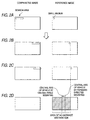
- a search area to be set in the comparative image is set in a striplike area as shown in Fig. 2A, which extends from a position substantially corresponding to a small region in the reference image toward the main camera. Therefore, as is apparent from Figs. 2B and 2C, for a small region located in a specific zone of the outside (right side) of the vehicle in the reference image, it is impossible to allocate a corresponding search area in the comparative image and obtain distance information thereon.
- An object of the present invention is to provide a structure for mounting a stereo camera apparatus which makes it possible to set a three-dimensional distance distribution symmetrically on left and right sides of the central axis of a vehicle and thereby produce a necessary and sufficient three-dimensional distance distribution.
- Another object of the present invention is to set a search margin in such a way that the infinite distance corresponding point can be detected even when the reference image is produced using up to extreme ends of camera frame.
- the objects can be achieved by a structure for mounting a stereo camera apparatus comprising a main camera and a sub-camera.
- the main camera takes photograph of an object in a shooting direction.
- the sub-camera takes photograph of the object from a point of view different from a point of view of the main camera.
- the main camera and sub-camera are disposed with a predetermined spacing in a direction substantially perpendicular to the shooting direction.
- Optical axes of the main camera and the sub-camera are inclined toward the main camera side with respect to the shooting direction between the main camera and the sub-camera.
- Each of the cameras may be made of CCD camera.
- the cameras may be mounted in the vicinity of a rear-view mirror of a vehicle, so as to take photographs of views outside the vehicle.
- the optical axis of the sub-camera is inclined toward the sub-camera side with respect to the optical axis of the main camera.
- angles of inclination of the main camera and the sub-camera are set to be such angles that make an area substantially left-right symmetric with respect to a central axis of a vehicle parallel to the shooting direction, the area being an area of three-dimensional distance distribution obtained on the basis of images photographed by the cameras.
- the optical axis of the sub-camera may inclined toward the sub-camera side with respect to the optical axis of the main camera.
- the structure of the invention further comprises:
- the objects can be also achieved by a structure for mounting a stereo camera apparatus which has a main camera and a sub-camera taking photograph of a common object in a shooting direction from different points of view and being disposed with a predetermined spacing in a baseline direction substantially perpendicular to the shooting direction, the stereo camera apparatus identifying a correlated destination of a first image photographed by the main camera within a second image photographed by the sub-camera and then calculating a parallax of the first image.
- Optical axes of the main camera and the sub-camera are inclined toward the main camera side with respect to the shooting direction between the main camera and the sub-camera.
- an acute angle defined between the optical axis of the main camera and the baseline direction is smaller than an acute angle defined between the optical axis of the sub-camera and the baseline direction.
- FIG. 1 is a schematic construction diagram of a stereoscopic image processing system
- Figs. 2A-D are respectively explanatory diagrams of areas for generating a three-dimensional distance distribution
- Fig. 3 is a top view of a stereo camera unit.
- the reference numeral 1 designates the stereoscopic image processing system which is installed on a vehicle like a motor vehicle and recognizes an object ahead of the vehicle.
- This stereoscopic image processing system 1 comprises a stereo camera unit 2 which takes stereoscopic photographs and an image processing unit 6 which produces a three-dimensional distance distribution of the object ahead of the vehicle by performing a stereoscopic image processing on a pair of images photographed by the stereo camera unit 2.
- the aforementioned stereo camera unit 2 is constructed mainly of a main camera 4, a sub-camera 5 and a camera stay 3.
- the main camera 4 and the sub-camera 5 are both made of CCD cameras, for example, and assembled to the camera stay 3 with a specific distance between them.
- the camera stay 3 is mounted in the vicinity of a rear-view mirror of the vehicle.
- the aforementioned main camera 4 is attached to a right end of the camera stay 3 and captures a reference image (right image) which is needed by the aforementioned image processing unit 6 when it performs the stereoscopic image processing.
- the aforementioned sub-camera 5 is attached to a left end of the camera stay 3 and captures a comparative image (left image) for the aforementioned stereoscopic image processing.
- the aforementioned image processing unit 6 calculates the three-dimensional distance distribution of objects outside the vehicle by image processing the reference image and the comparative image photographed by the aforementioned main camera 4 and sub-camera 5, and calculates a relative distance and relative speed between own vehicle and a vehicle running ahead by detecting road shapes and three-dimensional positions of a plurality of three-dimensional objects at a high speed based on the three-dimensional distance distribution information.
- this image processing unit 6 sets a search area (e.g., 4 ⁇ 128 pixels) in the comparative image for a small region (e.g., 4 ⁇ 4 pixels) in the reference image as shown in Figs. 2A and 2B. Then, the image processing unit 6 superimposes the small region on an area within the search area while successively shifting the small region pixel by pixel, and determines a position of an area within the search area corresponding to the small region, the corresponding area having image signal coincident with image signal of the small region. Thus, the image processing unit 6 obtains information on the distance to an object from a positional difference (parallax) of the same object on the two images.
- a search area e.g., 4 ⁇ 128 pixels
- a small region e.g., 4 ⁇ 4 pixels
- the aforementioned main camera 4 and sub-camera 5 are assembled to the camera stay 3 in such a way that their optical axes O1, O2 are inclined by angles ⁇ 1, ⁇ 2 toward the main camera 4 side (rightward), respectively, as shown in Fig. 3.
- the camera stay 3 is installed in vehicle interior such that its longitudinal direction would become perpendicular to the central axis of the vehicle (shooting direction) as shown in Fig. 1 and, therefore, the optical axes O1, O2 of the aforementioned main camera 4 and sub-camera 5 are inclined rightward by ⁇ 1, ⁇ 2 with respect to their shooting direction, respectively.
- the area of the three-dimensional distance distribution generating area is still offset toward the sub-camera 5 side (leftward) on the reference image as shown in Fig. 2D, the area of the three-dimensional distance distribution produced by the image processing unit 6 is well balanced showing left-right symmetry with respect to own vehicle.
- the angle of inclination ⁇ 1 of the main camera 4 and the angle of inclination ⁇ 2 of the sub-camera 5 are determined to satisfy the relationship ⁇ 1> ⁇ 2.
- the optical axis O2 of the sub-camera 5 is set such that it is inclined toward the sub-camera 5 side (leftward) with respect to the optical axis O1 of main camera 4.
- This arrangement is made to provide a search margin in the comparative image to enable detection of an infinite distance corresponding point in stereo matching executed by the image processing unit 6 by setting a left end of the comparative image to the outside (leftward) of a left end of the reference image. It is to be noted, however, that such a setting exerts its effects when the reference image is produced using up to extreme ends of camera frame.
- angles of inclination ⁇ 1, ⁇ 2 of the aforementioned main camera 4 and sub-camera 5 are optimally set depending on their mounting interval, focal length and the number of pixels of each camera, small regions and search area, etc. in stereoscopic image processing.
- an area of a three-dimensional distance distribution is set with left-right symmetry with respect to the central axis of a vehicle and a three-dimensional distance distribution having a necessary and sufficient area is obtained according to the present invention.
Landscapes
- Engineering & Computer Science (AREA)
- Physics & Mathematics (AREA)
- General Physics & Mathematics (AREA)
- Multimedia (AREA)
- Theoretical Computer Science (AREA)
- Signal Processing (AREA)
- Mechanical Engineering (AREA)
- Image Analysis (AREA)
- Measurement Of Optical Distance (AREA)
- Stereoscopic And Panoramic Photography (AREA)
- Length Measuring Devices By Optical Means (AREA)
- Cameras In General (AREA)
- Accessories Of Cameras (AREA)
- Fittings On The Vehicle Exterior For Carrying Loads, And Devices For Holding Or Mounting Articles (AREA)
- Image Processing (AREA)
- Testing, Inspecting, Measuring Of Stereoscopic Televisions And Televisions (AREA)
- Studio Devices (AREA)
- Closed-Circuit Television Systems (AREA)
Abstract
Description
Claims (8)
- A structure for mounting a stereo camera apparatus, comprising:a main camera (4) adapted to take photographs of an object in a shooting direction; anda sub-camera (5) adapted to take photographs of the object from a point of view different from a point of view of the of the main camera (4), the main camera (4) and the sub-camera (5) being disposed with a predetermined spacing in a direction substantially perpendicular to the shooting direction,wherein the optical axes of the main camera (4) and the sub-camera (3) are inclined toward the main camera side with respect to the shooting direction between the main camera (4) and the sub-camera (5).
- The structure according to claim 1,
wherein the angles of inclination (1, 2) of the main camera (4) and the sub-camera (5) are set to be such angles that make an area substantially left-right symmetric with respect to a central axis of a vehicle parallel to the shooting direction, the area being an area of three-dimensional distance distribution obtained on the basis of images photographed by the cameras (4,5). - The structure according to claim 1 or 2,
wherein the optical axis (O2) of the sub-camera (5) is inclined toward the sub-camera side with respect to the optical axis (O1) of the main camera (4). - The structure according to any of claims 1 to 3, further comprising:a camera stay (3) for mounting the cameras (4, 5) thereon, wherein the longitudinal direction of the camera stay (3) is substantially perpendicular to the shooting direction.
- The structure according to any of claims 1 to 4,
wherein each of the cameras (4, 5) is a CCD camera. - The structure according to any of claims 1 to 5,
wherein the cameras (4, 5) are mounted in the vicinity of a rear-view mirror of a vehicle, the cameras (4, 5) being adapted to take photographs of views outside the vehicle. - A structure for mounting a stereo camera apparatus (2) which has a main camera (4) and a sub-camera (5) adapted to take photographs of a common object in a shooting direction from different points of view and being disposed with a predetermined spacing in a baseline direction substantially perpendicular to the shooting direction, the stereo camera apparatus (2) being adapted to identify a correlated destination of a first image photographed by the main camera (4) within a second image photographed by the sub-camera (5) and then calculate a parallax of the first image,
wherein the optical axes (O1, O2) of the main camera (4) and the sub-camera (5) are inclined toward the main camera side with respect to the shooting direction between the main camera (4) and the sub-camera (5). - The structure according to claim 8,
wherein an acute angle defined between the optical axis (01) of the main camera (4) and the baseline direction is smaller than an acute angle defined between the optical axis (O2) of the sub-camera (5) and the baseline direction.
Priority Applications (1)
| Application Number | Priority Date | Filing Date | Title |
|---|---|---|---|
| EP05003579A EP1533653A1 (en) | 1999-09-22 | 2000-09-13 | A stereo camera apparatus |
Applications Claiming Priority (2)
| Application Number | Priority Date | Filing Date | Title |
|---|---|---|---|
| JP26955299 | 1999-09-22 | ||
| JP26955299A JP3349121B2 (en) | 1999-09-22 | 1999-09-22 | Stereo camera mounting structure |
Related Child Applications (1)
| Application Number | Title | Priority Date | Filing Date |
|---|---|---|---|
| EP05003579A Division EP1533653A1 (en) | 1999-09-22 | 2000-09-13 | A stereo camera apparatus |
Publications (3)
| Publication Number | Publication Date |
|---|---|
| EP1087257A2 true EP1087257A2 (en) | 2001-03-28 |
| EP1087257A3 EP1087257A3 (en) | 2003-05-07 |
| EP1087257B1 EP1087257B1 (en) | 2005-06-22 |
Family
ID=17473978
Family Applications (2)
| Application Number | Title | Priority Date | Filing Date |
|---|---|---|---|
| EP00119921A Expired - Lifetime EP1087257B1 (en) | 1999-09-22 | 2000-09-13 | Stereo camera apparatus in a vehicle |
| EP05003579A Withdrawn EP1533653A1 (en) | 1999-09-22 | 2000-09-13 | A stereo camera apparatus |
Family Applications After (1)
| Application Number | Title | Priority Date | Filing Date |
|---|---|---|---|
| EP05003579A Withdrawn EP1533653A1 (en) | 1999-09-22 | 2000-09-13 | A stereo camera apparatus |
Country Status (4)
| Country | Link |
|---|---|
| US (1) | US7106365B1 (en) |
| EP (2) | EP1087257B1 (en) |
| JP (1) | JP3349121B2 (en) |
| DE (1) | DE60020919T2 (en) |
Cited By (3)
| Publication number | Priority date | Publication date | Assignee | Title |
|---|---|---|---|---|
| WO2003053743A1 (en) * | 2001-12-20 | 2003-07-03 | Robert Bosch Gmbh | Stereo camera arrangement in a motor vehicle |
| DE10244148A1 (en) * | 2002-09-23 | 2004-04-08 | Daimlerchrysler Ag | Method and device for video-based observation and measurement of the lateral surroundings of a vehicle |
| WO2006052024A1 (en) | 2004-11-15 | 2006-05-18 | Hitachi, Ltd. | Stereo camera |
Families Citing this family (21)
| Publication number | Priority date | Publication date | Assignee | Title |
|---|---|---|---|---|
| DE10131196A1 (en) * | 2001-06-28 | 2003-01-16 | Bosch Gmbh Robert | Device for the detection of objects, people or the like |
| FR2898092B1 (en) * | 2006-03-06 | 2009-02-13 | Renault Sas | MIRROR DEVICE FOR MOTOR VEHICLE AND USE OF THE DEVICE |
| JP2008040115A (en) * | 2006-08-04 | 2008-02-21 | Fuji Heavy Ind Ltd | Stereo camera |
| ATE422185T1 (en) | 2006-08-24 | 2009-02-15 | Harman Becker Automotive Sys | METHOD FOR IMAGING THE ENVIRONMENT OF A VEHICLE AND SYSTEM THEREFOR |
| US20080165250A1 (en) * | 2007-01-08 | 2008-07-10 | Jeff Kirk Ekdahl | Vehicle security surveillance system |
| US8854465B1 (en) | 2007-01-08 | 2014-10-07 | Jason Charles McIntyre | Vehicle security surveillance system and method for surveillance of a vehicle |
| US20100289874A1 (en) * | 2009-05-15 | 2010-11-18 | Fuhua Cheng | Square tube mirror-based imaging system |
| US8964004B2 (en) | 2010-06-18 | 2015-02-24 | Amchael Visual Technology Corporation | Three channel reflector imaging system |
| JP5481337B2 (en) * | 2010-09-24 | 2014-04-23 | 株式会社東芝 | Image processing device |
| JP5704885B2 (en) * | 2010-10-25 | 2015-04-22 | オリンパスイメージング株式会社 | Imaging device, imaging method, and imaging control program |
| US8648808B2 (en) | 2011-09-19 | 2014-02-11 | Amchael Visual Technology Corp. | Three-dimensional human-computer interaction system that supports mouse operations through the motion of a finger and an operation method thereof |
| US9019352B2 (en) | 2011-11-21 | 2015-04-28 | Amchael Visual Technology Corp. | Two-parallel-channel reflector with focal length and disparity control |
| US9760092B2 (en) | 2012-03-16 | 2017-09-12 | Waymo Llc | Actively modifying a field of view of an autonomous vehicle in view of constraints |
| US9019603B2 (en) | 2012-03-22 | 2015-04-28 | Amchael Visual Technology Corp. | Two-parallel-channel reflector with focal length and disparity control |
| RU2582853C2 (en) * | 2012-06-29 | 2016-04-27 | Общество с ограниченной ответственностью "Системы Компьютерного зрения" | Device for determining distance and speed of objects based on stereo approach |
| US9557634B2 (en) | 2012-07-05 | 2017-01-31 | Amchael Visual Technology Corporation | Two-channel reflector based single-lens 2D/3D camera with disparity and convergence angle control |
| AU2014239979B2 (en) | 2013-03-15 | 2017-06-22 | Aurora Operations, Inc. | Methods, systems, and apparatus for multi-sensory stereo vision for robotics |
| JP2014182178A (en) * | 2013-03-18 | 2014-09-29 | Fuji Heavy Ind Ltd | Stereo camera unit |
| DE102014220585A1 (en) * | 2014-10-10 | 2016-04-14 | Conti Temic Microelectronic Gmbh | Stereo camera for vehicles |
| US10077007B2 (en) * | 2016-03-14 | 2018-09-18 | Uber Technologies, Inc. | Sidepod stereo camera system for an autonomous vehicle |
| US10967862B2 (en) | 2017-11-07 | 2021-04-06 | Uatc, Llc | Road anomaly detection for autonomous vehicle |
Family Cites Families (17)
| Publication number | Priority date | Publication date | Assignee | Title |
|---|---|---|---|---|
| JPS62155140A (en) * | 1985-12-27 | 1987-07-10 | Aisin Warner Ltd | Road image input system for controlling vehicle |
| JPH01177530A (en) * | 1988-01-08 | 1989-07-13 | Toshiba Corp | Supporting mechanism for stereoscopic camera |
| SE461619B (en) * | 1988-07-06 | 1990-03-05 | Hasselblad Ab Victor | DEVICE FOR CAMERAS CONCERNING A COMPOSITION OF A PHOTOCHEMICAL AND ELECTRONIC CAMERA |
| US5063441A (en) * | 1990-10-11 | 1991-11-05 | Stereographics Corporation | Stereoscopic video cameras with image sensors having variable effective position |
| JPH05265547A (en) * | 1992-03-23 | 1993-10-15 | Fuji Heavy Ind Ltd | On-vehicle outside monitoring device |
| WO1994010604A1 (en) * | 1992-10-29 | 1994-05-11 | Aea O´Donnell, Inc. | Automated stereoscopic image acquisition and storage system |
| JP2887039B2 (en) * | 1993-03-26 | 1999-04-26 | 三菱電機株式会社 | Vehicle periphery monitoring device |
| JP3522317B2 (en) * | 1993-12-27 | 2004-04-26 | 富士重工業株式会社 | Travel guide device for vehicles |
| US5473364A (en) * | 1994-06-03 | 1995-12-05 | David Sarnoff Research Center, Inc. | Video technique for indicating moving objects from a movable platform |
| EP0696144A3 (en) * | 1994-08-02 | 1996-04-24 | Canon Kk | Multilens imaging apparatus comprising a corresponding point extraction unit |
| JP3539788B2 (en) * | 1995-04-21 | 2004-07-07 | パナソニック モバイルコミュニケーションズ株式会社 | Image matching method |
| JPH0997342A (en) * | 1995-08-03 | 1997-04-08 | Sumitomo Electric Ind Ltd | Tree separation distance measurement system |
| JP3866328B2 (en) * | 1996-06-06 | 2007-01-10 | 富士重工業株式会社 | Vehicle peripheral three-dimensional object recognition device |
| GB2313977A (en) | 1996-06-07 | 1997-12-10 | Chairman International Limited | Telephone set |
| US5652616A (en) * | 1996-08-06 | 1997-07-29 | General Instrument Corporation Of Delaware | Optimal disparity estimation for stereoscopic video coding |
| JP3147002B2 (en) * | 1996-09-26 | 2001-03-19 | 富士電機株式会社 | Correction method of distance detection value |
| JP4172554B2 (en) * | 1998-03-12 | 2008-10-29 | 富士重工業株式会社 | Stereo camera adjustment device |
-
1999
- 1999-09-22 JP JP26955299A patent/JP3349121B2/en not_active Expired - Fee Related
-
2000
- 2000-09-13 DE DE60020919T patent/DE60020919T2/en not_active Expired - Lifetime
- 2000-09-13 EP EP00119921A patent/EP1087257B1/en not_active Expired - Lifetime
- 2000-09-13 EP EP05003579A patent/EP1533653A1/en not_active Withdrawn
- 2000-09-21 US US09/667,424 patent/US7106365B1/en not_active Expired - Lifetime
Cited By (6)
| Publication number | Priority date | Publication date | Assignee | Title |
|---|---|---|---|---|
| WO2003053743A1 (en) * | 2001-12-20 | 2003-07-03 | Robert Bosch Gmbh | Stereo camera arrangement in a motor vehicle |
| US7111996B2 (en) | 2001-12-20 | 2006-09-26 | Robert Bosch Gmbh | Stereo camera arrangement in a motor vehicle |
| EP2474451A1 (en) * | 2001-12-20 | 2012-07-11 | Robert Bosch GmbH | Stereo camera arrangement in a vehicle |
| DE10244148A1 (en) * | 2002-09-23 | 2004-04-08 | Daimlerchrysler Ag | Method and device for video-based observation and measurement of the lateral surroundings of a vehicle |
| WO2006052024A1 (en) | 2004-11-15 | 2006-05-18 | Hitachi, Ltd. | Stereo camera |
| EP1816514A4 (en) * | 2004-11-15 | 2010-11-10 | Hitachi Ltd | CAMERA STEREO |
Also Published As
| Publication number | Publication date |
|---|---|
| JP3349121B2 (en) | 2002-11-20 |
| EP1533653A1 (en) | 2005-05-25 |
| EP1087257A3 (en) | 2003-05-07 |
| US7106365B1 (en) | 2006-09-12 |
| JP2001092048A (en) | 2001-04-06 |
| DE60020919D1 (en) | 2005-07-28 |
| EP1087257B1 (en) | 2005-06-22 |
| DE60020919T2 (en) | 2006-05-18 |
Similar Documents
| Publication | Publication Date | Title |
|---|---|---|
| US7106365B1 (en) | Stereo camera apparatus with a main camera and a sub-camera where the sub-camera has a point of view difference from the point of view of the main camera | |
| EP2071491B1 (en) | Stereo camera device | |
| WO2019167531A1 (en) | Stereo camera device | |
| US10992920B2 (en) | Stereo image processing device | |
| JPH10341458A (en) | In-vehicle stereo camera calibration method and in-vehicle stereo camera to which the method is applied | |
| US6366691B1 (en) | Stereoscopic image processing apparatus and method | |
| JP2020051942A (en) | Vehicle traveling environment detector and traveling control system | |
| CN113646607A (en) | Object position detection device, travel control system, and travel control method | |
| JP3961584B2 (en) | Lane marking detector | |
| JPH09223227A (en) | Vehicle environment recognition device | |
| JP3868915B2 (en) | Forward monitoring apparatus and method | |
| JP6489645B2 (en) | Image processing device | |
| JPH07296291A (en) | Traveling lane detector for vehicle | |
| CN115943287B (en) | Vehicle posture inference system and vehicle posture inference method | |
| JP2006031101A (en) | Image generation method and device therefor | |
| JPH1141521A (en) | Imaging device, inter-vehicle distance measuring device, and inter-vehicle distance measuring method | |
| JP3099692B2 (en) | Method of measuring the position of an object on a traveling path | |
| JP6600177B2 (en) | Image processing device | |
| JP6619589B2 (en) | Image processing device | |
| WO2025057546A1 (en) | On-board image processing device | |
| CN110414487B (en) | Method and device for identifying lane line | |
| JP2000131064A (en) | Height measurement method | |
| JP2008040115A (en) | Stereo camera | |
| KR20240130623A (en) | Distance measurement device, movable apparatus, and control method | |
| JP3154671B2 (en) | Travel zone detection device for vehicles |
Legal Events
| Date | Code | Title | Description |
|---|---|---|---|
| PUAI | Public reference made under article 153(3) epc to a published international application that has entered the european phase |
Free format text: ORIGINAL CODE: 0009012 |
|
| AK | Designated contracting states |
Kind code of ref document: A2 Designated state(s): AT BE CH CY DE DK ES FI FR GB GR IE IT LI LU MC NL PT SE |
|
| AX | Request for extension of the european patent |
Free format text: AL;LT;LV;MK;RO;SI |
|
| PUAL | Search report despatched |
Free format text: ORIGINAL CODE: 0009013 |
|
| AK | Designated contracting states |
Designated state(s): AT BE CH CY DE DK ES FI FR GB GR IE IT LI LU MC NL PT SE |
|
| AX | Request for extension of the european patent |
Extension state: AL LT LV MK RO SI |
|
| 17P | Request for examination filed |
Effective date: 20030716 |
|
| 17Q | First examination report despatched |
Effective date: 20030811 |
|
| AKX | Designation fees paid |
Designated state(s): DE GB |
|
| GRAP | Despatch of communication of intention to grant a patent |
Free format text: ORIGINAL CODE: EPIDOSNIGR1 |
|
| RTI1 | Title (correction) |
Free format text: STEREO CAMERA APPARATUS IN A VEHICLE |
|
| GRAS | Grant fee paid |
Free format text: ORIGINAL CODE: EPIDOSNIGR3 |
|
| GRAA | (expected) grant |
Free format text: ORIGINAL CODE: 0009210 |
|
| AK | Designated contracting states |
Kind code of ref document: B1 Designated state(s): DE GB |
|
| REG | Reference to a national code |
Ref country code: GB Ref legal event code: FG4D |
|
| REF | Corresponds to: |
Ref document number: 60020919 Country of ref document: DE Date of ref document: 20050728 Kind code of ref document: P |
|
| PLBE | No opposition filed within time limit |
Free format text: ORIGINAL CODE: 0009261 |
|
| STAA | Information on the status of an ep patent application or granted ep patent |
Free format text: STATUS: NO OPPOSITION FILED WITHIN TIME LIMIT |
|
| 26N | No opposition filed |
Effective date: 20060323 |
|
| PGFP | Annual fee paid to national office [announced via postgrant information from national office to epo] |
Ref country code: GB Payment date: 20090909 Year of fee payment: 10 |
|
| GBPC | Gb: european patent ceased through non-payment of renewal fee |
Effective date: 20100913 |
|
| PG25 | Lapsed in a contracting state [announced via postgrant information from national office to epo] |
Ref country code: GB Free format text: LAPSE BECAUSE OF NON-PAYMENT OF DUE FEES Effective date: 20100913 |
|
| REG | Reference to a national code |
Ref country code: DE Ref legal event code: R082 Ref document number: 60020919 Country of ref document: DE Representative=s name: MEISSNER BOLTE PATENTANWAELTE RECHTSANWAELTE P, DE Ref country code: DE Ref legal event code: R081 Ref document number: 60020919 Country of ref document: DE Owner name: SUBARU CORPORATION, JP Free format text: FORMER OWNER: FUJI JUKOGYO K.K., TOKIO/TOKYO, JP |
|
| PGFP | Annual fee paid to national office [announced via postgrant information from national office to epo] |
Ref country code: DE Payment date: 20190918 Year of fee payment: 20 |
|
| REG | Reference to a national code |
Ref country code: DE Ref legal event code: R071 Ref document number: 60020919 Country of ref document: DE |