EP1087249A2 - Image stabilizing apparatus - Google Patents
Image stabilizing apparatus Download PDFInfo
- Publication number
- EP1087249A2 EP1087249A2 EP00120567A EP00120567A EP1087249A2 EP 1087249 A2 EP1087249 A2 EP 1087249A2 EP 00120567 A EP00120567 A EP 00120567A EP 00120567 A EP00120567 A EP 00120567A EP 1087249 A2 EP1087249 A2 EP 1087249A2
- Authority
- EP
- European Patent Office
- Prior art keywords
- image stabilizing
- pulse width
- driving circuit
- power voltage
- stabilizing apparatus
- Prior art date
- Legal status (The legal status is an assumption and is not a legal conclusion. Google has not performed a legal analysis and makes no representation as to the accuracy of the status listed.)
- Granted
Links
- 230000000087 stabilizing effect Effects 0.000 title claims abstract description 36
- 239000000725 suspension Substances 0.000 claims abstract description 44
- 230000003287 optical effect Effects 0.000 claims description 46
- 230000002708 enhancing effect Effects 0.000 claims description 4
- 230000007423 decrease Effects 0.000 abstract description 4
- 230000036544 posture Effects 0.000 description 7
- 238000004091 panning Methods 0.000 description 6
- 239000000919 ceramic Substances 0.000 description 5
- 230000003321 amplification Effects 0.000 description 4
- 238000010586 diagram Methods 0.000 description 4
- 238000003199 nucleic acid amplification method Methods 0.000 description 4
- 230000003247 decreasing effect Effects 0.000 description 3
- 230000002349 favourable effect Effects 0.000 description 3
- 230000004907 flux Effects 0.000 description 3
- 238000001514 detection method Methods 0.000 description 2
- 238000013459 approach Methods 0.000 description 1
- 239000003990 capacitor Substances 0.000 description 1
- 230000008094 contradictory effect Effects 0.000 description 1
- 238000007796 conventional method Methods 0.000 description 1
- 230000000694 effects Effects 0.000 description 1
- 230000020169 heat generation Effects 0.000 description 1
- 238000000034 method Methods 0.000 description 1
Images




Classifications
-
- G—PHYSICS
- G02—OPTICS
- G02B—OPTICAL ELEMENTS, SYSTEMS OR APPARATUS
- G02B27/00—Optical systems or apparatus not provided for by any of the groups G02B1/00 - G02B26/00, G02B30/00
- G02B27/64—Imaging systems using optical elements for stabilisation of the lateral and angular position of the image
- G02B27/646—Imaging systems using optical elements for stabilisation of the lateral and angular position of the image compensating for small deviations, e.g. due to vibration or shake
-
- H—ELECTRICITY
- H04—ELECTRIC COMMUNICATION TECHNIQUE
- H04N—PICTORIAL COMMUNICATION, e.g. TELEVISION
- H04N23/00—Cameras or camera modules comprising electronic image sensors; Control thereof
- H04N23/60—Control of cameras or camera modules
- H04N23/68—Control of cameras or camera modules for stable pick-up of the scene, e.g. compensating for camera body vibrations
- H04N23/681—Motion detection
- H04N23/6812—Motion detection based on additional sensors, e.g. acceleration sensors
-
- G—PHYSICS
- G03—PHOTOGRAPHY; CINEMATOGRAPHY; ANALOGOUS TECHNIQUES USING WAVES OTHER THAN OPTICAL WAVES; ELECTROGRAPHY; HOLOGRAPHY
- G03B—APPARATUS OR ARRANGEMENTS FOR TAKING PHOTOGRAPHS OR FOR PROJECTING OR VIEWING THEM; APPARATUS OR ARRANGEMENTS EMPLOYING ANALOGOUS TECHNIQUES USING WAVES OTHER THAN OPTICAL WAVES; ACCESSORIES THEREFOR
- G03B17/00—Details of cameras or camera bodies; Accessories therefor
- G03B17/26—Holders for containing light sensitive material and adapted to be inserted within the camera
-
- G—PHYSICS
- G03—PHOTOGRAPHY; CINEMATOGRAPHY; ANALOGOUS TECHNIQUES USING WAVES OTHER THAN OPTICAL WAVES; ELECTROGRAPHY; HOLOGRAPHY
- G03B—APPARATUS OR ARRANGEMENTS FOR TAKING PHOTOGRAPHS OR FOR PROJECTING OR VIEWING THEM; APPARATUS OR ARRANGEMENTS EMPLOYING ANALOGOUS TECHNIQUES USING WAVES OTHER THAN OPTICAL WAVES; ACCESSORIES THEREFOR
- G03B5/00—Adjustment of optical system relative to image or object surface other than for focusing
-
- H—ELECTRICITY
- H04—ELECTRIC COMMUNICATION TECHNIQUE
- H04N—PICTORIAL COMMUNICATION, e.g. TELEVISION
- H04N23/00—Cameras or camera modules comprising electronic image sensors; Control thereof
- H04N23/60—Control of cameras or camera modules
- H04N23/68—Control of cameras or camera modules for stable pick-up of the scene, e.g. compensating for camera body vibrations
-
- H—ELECTRICITY
- H04—ELECTRIC COMMUNICATION TECHNIQUE
- H04N—PICTORIAL COMMUNICATION, e.g. TELEVISION
- H04N23/00—Cameras or camera modules comprising electronic image sensors; Control thereof
- H04N23/60—Control of cameras or camera modules
- H04N23/68—Control of cameras or camera modules for stable pick-up of the scene, e.g. compensating for camera body vibrations
- H04N23/682—Vibration or motion blur correction
- H04N23/685—Vibration or motion blur correction performed by mechanical compensation
- H04N23/687—Vibration or motion blur correction performed by mechanical compensation by shifting the lens or sensor position
-
- G—PHYSICS
- G03—PHOTOGRAPHY; CINEMATOGRAPHY; ANALOGOUS TECHNIQUES USING WAVES OTHER THAN OPTICAL WAVES; ELECTROGRAPHY; HOLOGRAPHY
- G03B—APPARATUS OR ARRANGEMENTS FOR TAKING PHOTOGRAPHS OR FOR PROJECTING OR VIEWING THEM; APPARATUS OR ARRANGEMENTS EMPLOYING ANALOGOUS TECHNIQUES USING WAVES OTHER THAN OPTICAL WAVES; ACCESSORIES THEREFOR
- G03B2205/00—Adjustment of optical system relative to image or object surface other than for focusing
- G03B2205/0007—Movement of one or more optical elements for control of motion blur
Definitions
- the present invention relates to an image stabilizing apparatus, disposed within an optical apparatus such as monocular, binoculars, and video camera, for preventing optical images from being observed in a blurred state due to the fluctuation in emission angle of luminous flux from an observation object with respect to the optical axis of the optical apparatus when the optical apparatus is vibrated.
- an optical apparatus such as monocular, binoculars, and video camera
- an optical apparatus aimed at optical observation such as monocular and binoculars
- the vibration or rocking of the airplane, vehicle, or the like is transmitted to the optical apparatus, so that the emission angle of luminous flux from an observation object with respect to the optical axis fluctuates, whereby the optical image to be observed often deteriorates.
- the vibration transmitted to such an optical apparatus has a small amplitude, the angle of fluctuation with respect to the optical axis is enlarged since the field of view is narrow in the monocular, binoculars, and the like, and since the observation object is viewed under magnification therein.
- the observation object may rapidly move within the field of view, and go out of sight when the angle of fluctuation is large, which is inconvenient.
- the angle fluctuating speed of the image of observation object is observed as being increased by the power of optical apparatus even when the fluctuation angle is relatively small, whereby the image blurs and deteriorates, which is inconvenient.
- Japanese Patent Publication No. 57-37852 discloses binoculars comprising therein anti-vibration means utilizing a rotary inertial member (gyro motor) in order to correct the blur of observation images in the binoculars.
- an erect prism is disposed on the optical axis between an objective lens and an eyepiece of the binoculars and is secured onto gimbal suspension means, such that the erect prism is held in substantially the same posture even when the binoculars are vibrated due to camera shake or the like, so as to prevent the observation image of binoculars from blurring.
- the effective diameter of objective lenses is made greater along with the increase in power or resolution of binoculars, then the erect prism becomes larger, whereby a large inertial force is required, which enhances the above-mentioned problems, and the power consumption increases along therewith.
- the assignee of the present application has proposed an image stabilizing apparatus (Japanese Unexamined Patent Publication No. 6-250100) in which an angular velocity sensor is mounted to gimbal suspension means in place of the above-mentioned rotary inertial member, and the pivoting of the gimbal suspension means is controlled according to the output value from the angular velocity sensor, so as to fix the posture of the erect prism with respect to the earth (inertial system).
- the erect prism held with the gimbal suspension means basically has an inertial force. In particular, its posture-keeping capability against vibrations with a relatively large amplitude is high with respect to high-speed vibrations with a high vibration frequency.
- control power for the rotational position according to the angular velocity sensor can be kept small.
- active driving sections are needed, and it is necessary for the driving sections to be operated at a high speed in order to correct a large amplitude in high-frequency vibrations, whereby correction in a wide angle range is difficult.
- the above-mentioned gimbal suspension means is pivoted by an actuator such as motor about two pivotal axes extending sidewise and vertical directions of the optical apparatus, respectively.
- the actuator is driven by PWM control, which is excellent in response and is favorable in terms of power utilization efficiency.
- a pulse waveform is outputted from pivoting control means to a driving circuit, and an actuator is driven with a power corresponding to the pulse width of output waveform. Consequently, there is a problem that, if the power voltage of the driving circuit drops while the apparatus is in use as in the case employing a battery power source, then the actuator driving power may decrease, whereby the aimed pivoting control cannot be carried out.
- an object of the present invention to provide an image stabilizing apparatus configured such that an actuator for pivoting gimbal suspension means is driven under PWM control by way of a driving circuit, in which, even when the power voltage of the driving circuit drops while the apparatus is in use, the actuator driving power can be kept from decreasing, so as to carry out the aimed pivoting control.
- the present invention provides an image stabilizing apparatus mounted in an optical apparatus having a monocular or binocular optical system in which an erect prism is disposed between an objective lens and an eyepiece, whereas the objective lens and eyepiece of the optical system are secured within a case;
- the correction rate of pulse width is set to the reciprocal of drop rate of power voltage.
- the image stabilizing apparatus further comprise maximum limit value correcting means for enhancing the maximum limit value.
- a correction rate of the maximum limit value is set to the same value as the correction rate of pulse width.
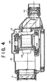
- Figs. 2 to 5 are a sectional view taken along a horizontal plane, frontal sectional view, lateral sectional view, and perspective view showing the state where the image stabilizing apparatus in accordance with an embodiment of the present invention is incorporated in binoculars, respectively.
- the binoculars in which the image stabilizing apparatus 20 of this embodiment is incorporated in a case 30 comprise a pair of objective lens systems 1a, 1b; a pair of eyepiece systems 2a, 2b; and a pair of erect prisms 3a, 3b.
- the objective lens 1a, eyepiece 2a, and erect prism 3a constitute a first telescope system 10a.
- the objective lens 1b, eyepiece 2b, and erect prism 3b constitute a second telescope system 10b.
- the first and second telescope systems 10a, 10b as a pair constitute a binocular system.
- a pair of objective lens systems 1a, 1b and a pair of eyepieces 2a, 2b, constituting the binocular system, are secured to the case 30 of the optical apparatus.
- the erect prisms 3a, 3b are pivotally attached to the case 30 by way of gimbal suspension members 7, 107 having pivotal axes 6, 106 (see Fig. 6) extending in the vertical direction of the apparatus (the direction orthogonal to both the optical axis and aligning direction of objective lens systems 1a, 1b) and the sidewise direction of the apparatus (the aligning direction of objective lenses 1a, 1b), respectively.
- the back side of the case 30 is provided with a main switch 50 and a gain changeover instruction switch 40 which enables the switching of gain, in a control loop which will be explained later, to be operated from the outside.
- the optical apparatus attains a configuration of a common binocular system in the state where the gimbal suspension members 7, 107 having the above-mentioned erect prisms 3a, 3b attached thereto are fixed with respect to the case 30, i.e., where the erect prisms 3a, 3b attached to the gimbal suspension members 7, 107 are resultantly secured to the case 30, in Fig. 6.
- the respective optical axes 4a, 4b of the telescope optical systems 10a, 10b at this time will be referred to as optical axes of the optical apparatus.
- the inner gimbal suspension member 107 is axially supported by the outer gimbal suspension member 7, so that the gimbal suspension device has an inner/outer double structure. While the outer gimbal suspension member 7 is pivoted by the pivotal axis 6 extending in the sidewise direction of the apparatus, so as to correct the blurring of images with respect to the vertical direction; the inner gimbal suspension member 107 is pivoted by the pivotal axis 106 extending in the vertical direction of the apparatus, so as to correct the blurring of images with respect to the sidewise direction.
- the erect prisms 3a, 3b are attached to the inner gimbal suspension member 107.
- the vertical relationship is shown opposite to that in Figs. 2 to 5.
- An angular velocity sensor 8 is secured to the center part of the upper wall portion of the outer gimbal suspension member 7, whereas an angular velocity sensor 108 is secured to the center part of the front wall portion of the inner gimbal suspension member 107.
- the angular velocity sensor 8 is a sensor which detects, when the outer gimbal suspension member 7 pivots in the direction of arrow B along with the vertical fluctuation of the case 30, its rotational angular velocity ⁇ 1 .
- the angular velocity sensor 108 is a sensor which detects, when the inner gimbal suspension member 107 pivots in the direction of arrow D along with the sidewise fluctuation of the case 30, its rotational angular velocity ⁇ 2 .
- a position sensor 9 for detecting the rotational angle ⁇ 1 of the pivotal axis 6 is attached to one end of the pivotal axis 6. Attached to the other end of the pivotal axis 6 is a rotary motor 5 for pivoting the pivotal axis 6 of the gimbal suspension member 7 so as to cause the erect prisms 3a, 3b to always restore their initial postures against the fluctuation of the case 30 according to the detected values from the angular velocity sensor 8 and position sensor 9.
- a position sensor 109 for detecting the rotational angle ⁇ 2 of the pivotal axis 106 is attached to one end of the pivotal axis 106. Attached to the other end of the pivotal axis 106 is a rotary motor 105 for pivoting the pivotal axis 106 of the gimbal suspension member 107 so as to cause the erect prisms 3a, 3b to always restore their initial postures against the fluctuation of the case 30 with respect to the sidewise direction according to the detected values from the angular velocity sensor 108 and position sensor 109.
- this apparatus comprises amplifiers 11a, 11b for amplifying the angular velocity signal from the angular velocity sensor 8 and the angular signal from the position sensor 9, respectively; a CPU 12 for computing the amount of driving of the rotary motor 5 so as to cause the erect prisms 3a, 3b to restore their original postures according to the angular velocity signal and angular signal and outputting a control signal based on this computation; and a motor driving circuit 13 for amplifying the control signal from the CPU 12 and driving the rotary motor 5.
- the driving control of the rotary motor 5 in the CPU 12 is carried out by PWM (Pulse Width Modulation) control which is excellent in response and favorable in terms of power utilization efficiency.
- PWM Pulse Width Modulation
- a ROM 12a storing various kinds of programs
- the gain changeover instruction switch 40 for instructing the CPU 12 to change the gain in the control loop.
- the detected signals from the angular velocity sensor 8 and position sensor 9 are converted into a control signal by a control loop similar to that shown in Fig. 7, and the rotary motor 105 is driven by this control signal.
- the CPU 12 may be used in common.
- This control loop is constituted by two feedback loops, i.e., a velocity (angular velocity) feedback loop and a positional (angle) feedback loop. Also, this control loop is constituted by a combination of a software loop constructed by microprocessor programs in the CPU 12, and a hardware loop.
- the velocity feedback loop detects the angular velocity ⁇ of a gimbal suspension device 70 (7, 107) about the pivotal axis 6, 106 with an angular velocity sensor 61 (8, 108).
- detected value ⁇ is amplified by a hardware amplifier 62 and then is negatively fed back to a motor driving system 68 (first velocity feedback loop).
- a motor driving system 68 first velocity feedback loop
- an opposite rotational torque is generated in a motor 69, whereby control is effected such that the gimbal suspension device 70 restores its original posture against vibrations such as camera shake, i.e., the erect prisms 3a, 3b are secured with respect to the earth (inertial system) against vibrations with a large angular velocity.
- the value detected by the angular velocity sensor 61 is fed into an integrator 65 by way of a subtractor 63 and an amplifier 64. Then, in a subtractor 66, the detected value directly fed from the amplifier 62 is subtracted from the output value of the integrator 65, and the result of subtraction is negatively fed back to the motor driving system 68 (second velocity feedback loop). Since the value detected by the angular velocity sensor 61 is negatively fed back by way of the integrator 65, the control system can function even when the offset is zero with respect to a velocity command, i.e., when a velocity input value and a velocity output value of the feedback loop are identical to each other. Also, since the loop gain can be duplexed, the gimbal suspension device 70 can be stabilized at a higher speed (stabilizing accuracy can be raised).
- the integrator 65 functions to average input values, whereas its output value is subjected to subtraction with the detected angular velocity value in the subtractor 66. Therefore, the integrator 65 can be considered to have a damper function for preventing the first velocity feedback loop from oscillating.
- the position feedback loop detects the angular position ⁇ of the gimbal suspension device 70 about the pivotal axis 6, 106 with a position sensor 81 (9, 109), amplifies thus detected value with a hardware amplifier 82, and then sends back thus amplified value to the motor driving system 68, thereby controlling the rotary motor 69 (5, 105) such that the gimbal suspension device 70 approaches the angular position ⁇ 0 of the midpoint on the collimation axis.
- This position feedback loop is configured such that the detected signal from the position sensor 81 is basically fed back by way of a first amplifier 83.
- the amplification factor of the first amplifier 83 has such a linear characteristic that it gradually increases as the pivoting angle of the gimbal suspension device 70 enhances, whereas the gradient of this linear characteristic is set to a relatively small value. Namely, the first amplifier 83 is set so as to suppress the gain of position feedback loop (position gain) to a relatively low level, thereby yielding a mode (anti-vibration mode) attributing more importance to anti-vibration performances.
- this embodiment is configured such that a second amplifier 84 having a higher amplification factor is disposed within the position feedback loop in parallel with the first amplifier 83 having a lower amplification factor, whereas the first amplifier 83 and second amplifier 84 can be switched therebetween by a software switch section 85. While the amplification factor of the second amplifier 84 has such a linear characteristic that it gradually increases as the pivoting angle of the gimbal suspension device 70 enhances, the gradient of this linear characteristic is set to a value much greater than that in the first amplifier 83.
- the changeover of the software switch section 85 is carried out when the operator switches the mode changeover switch 40 on the back side of the case 30 in response to circumstances.
- the software switch section 85 is connected to the second amplifier 84, the position gain is set greater, whereby a mode (panning mode) attributing more importance to tracking performances is attained.
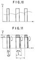
- Figs. 9 and 10 are a circuit diagram and waveform chart showing the contents of PWM control in an easily understandable manner, respectively.
- the CPU 12 generates a pulse waveform and outputs it to the motor driving circuit 13, whereas the motor driving circuit 13 drives the rotary motor 5 with a power corresponding to the pulse width of the output waveform. Since capacitors C1 and C2 are connected to both terminals of the rotary motor 5, respectively, the voltage actually applied to the rotary motor 5 has a waveform indicated by the broken curve in Fig. 10.
- the CPU 12 enhances the pulse width of the waveform outputted from the CPU 12 to the motor driving circuit 13 as shown in Fig. 11.
- the power voltage V p is fed as a constant voltage V cc (5 V) into the CPU 12 by way of the regulator, the power voltage V p is read out by the CPU 12 at its A/D terminal. If thus read-out power voltage V p drops to a voltage V 2 lower than its rated voltage V 2 , then the pulse width of output waveform is corrected so as to increase from W 1 to W 2 according to the amount of drop.
- the correction rate (W 2 /W 1 ) at this time is set to the reciprocal (V 1 /V 2 ) of drop rate of the power voltage V p .
- a maximum limit value W max is set for the pulse width of output waveform, whereas the CPU 12 enhances the maximum limit value W max when the power voltage V p of the motor driving circuit 13 drops.
- the maximum limit value W max is set to 1/2 of the period T of the waveform outputted from the CPU 12, whereas its correction rate is set to the same value as the correction rate (W 2 /W 1 ) of pulse width.
- the rotary motor 5 is driven by the CPU 12 under PWM control by way of the motor driving circuit 13, if the power voltage V p of the motor driving circuit 13 drops as the battery is used, then the pulse width of output waveform is corrected by the CPU 12 so as to increase in response to the drop. Therefore, the actuator driving power can be kept from decreasing, so as to carry out the aimed pivoting control in this embodiment.
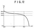
- Fig. 12 is a chart showing how the power voltage V p changes as a battery is used in the case where a battery power source comprising four AA alkaline cells in series is employed in the image stabilizing apparatus of this embodiment.
- the power voltage V p gradually drops from a voltage slightly higher than its rated voltage of 6 V as it is used, so as to become about 5.2 V in two hours and about 4 V in four hours, and drastically drops thereafter.
- the pulse width is not corrected so as to increase, then only about two hours of battery life are assured since a driving voltage of at least about 5.2 V is required for driving the rotary motor 5.
- the pulse width is enhanced in response to the drop in power voltage V p , whereby the rotary motor 5 can fully be driven even at a driving voltage of about 4.5 V. Therefore, the battery life can greatly be elongated in accordance with this embodiment.
- the maximum limit value W max is corrected by the CPU 12 so as to increase when the power voltage V p of the motor driving circuit 13 drops. Therefore, it is possible to reduce the fear of the enhanced pulse width W 2 exceeding the maximum limit value W max and thus being limited thereby. Since the correction rate of the maximum limit value W max is set to the same value as the correction rate (W 2 /W 1 ) of pulse width in particular, the pulse width W 2 would not exceed the maximum limit value W max , whereby a required actuator driving power can always be secured in this embodiment.
- erect prisms 3a, 3b examples include Schmidt erect prisms, Abbe erect prisms, bauern fend erect prisms, porro erect prisms, and roof erect prisms.
- Fig. 8 shows a Schmidt erect prism.
- the Schmidt erect prism is constituted by prisms 23, 24 as depicted, whereas a part 25 of the prism 24 acts as a roof reflecting surface.
- Such an erect prism in which the entrance optical axis 21 and exit optical axis 22 can be formed on the same line has such a property that, as shown in Fig. 8, a light beam 21' which is parallel to the optical axis 21 and separated upward from the optical axis 21 by h becomes, after passing through the erect prism, a light beam 22' which is parallel to the optical axis 22 and separated downward from the optical axis 22 by h.
- the angular velocity sensor 8, 108 is a piezoelectric vibrating gyro sensor comprising a columnar vibrator which is shaped like a cylinder or the like and a plurality of piezoelectric ceramic pieces and utilizing Coriolis force, in which at least two piezoelectric ceramic pieces for detection and at least one piezoelectric ceramic piece for feedback are disposed on a side face of the columnar vibrator.
- the piezoelectric ceramic pieces for detection output respective detected signals having values different from each other depending on the vibration. When their difference is computed, an angular velocity is obtained.
- the piezoelectric ceramic for feedback is used for correcting the phase of detected signals.
- the image stabilizing apparatus 20 itself can attain a simple structure and a very small size. Also, since it has a high S/N ratio and a high precision, the angular velocity control can attain a high accuracy.
- the image stabilizing apparatus of the present invention is not limited to the one in accordance with the above-mentioned embodiment, and can be modified in various manners.
- the angular velocity information detecting means not only the piezoelectric vibrating gyro sensor of a columnar vibrator type, but also piezoelectric vibrating gyro sensors of various types such as a triangular prism vibrator type, a quadrangular prism vibrator type, and a tuning-fork-shaped vibrator type can be used. Further, various kinds of other angular velocity sensors can be used.
- angular position detecting means various angular sensors such as resolver, synchro, rotary encoder, and the like can also be used in place of the above-mentioned position sensor.
- the image stabilizing apparatus of the present invention can have a configuration applicable to a monocular as well. Also, similar effects can be obtained when the apparatus is mounted to a camera such as video camera.
- the image stabilizing apparatus of the present invention is configured such that the actuator for pivoting the gimbal suspension means is driven under PWM control by way of a driving circuit, the pulse width of waveform outputted to the driving circuit is corrected so as to increase when the power voltage of the driving circuit drops while the apparatus is in use, whereby the actuator driving power can be prevented from decreasing, so as to carry out the aimed pivoting control.
- the pulse width of waveform outputted from a CPU to the driving circuit is enhanced when the power voltage V p in the driving circuit drops.
- the CPU reads out the power voltage V p and enhances the pulse width of output waveform from W 1 to W 2 as the power voltage V p decreases from its rated voltage V 1 to a lower voltage V 2 .
- the correction rate (W 2 /W 1 ) is set to the reciprocal (V 1 /V 2 ) of the drop rate of power voltage V p , so as to yield an appropriate actuator driving power in response to the drop in power voltage V p .
Landscapes
- Physics & Mathematics (AREA)
- Engineering & Computer Science (AREA)
- Multimedia (AREA)
- Signal Processing (AREA)
- General Physics & Mathematics (AREA)
- Optics & Photonics (AREA)
- Telescopes (AREA)
- Adjustment Of Camera Lenses (AREA)
- Control Of Position Or Direction (AREA)
- Control Of Stepping Motors (AREA)
Abstract
Description
Claims (4)
- An image stabilizing apparatus mounted in an optical apparatus having a monocular or binocular optical system in which an erect prism is disposed between an objective lens and an eyepiece, whereas said objective lens and eyepiece of said optical system are secured within a case;said image stabilizing apparatus comprising:gimbal suspension means, adapted to pivotally attach said erect prism to said case, having two pivotal axes extending sidewise and vertical directions of said optical apparatus, respectively;an actuator for pivoting said gimbal suspension means about said two pivotal axes;pivoting control means for driving said actuator under PWM control by way of a driving circuit and controlling said pivoting of said gimbal suspension means about said two pivotal axes so as to fix said erect prism with respect to an inertial system; andpulse width correcting means for enhancing, when a power voltage of said driving circuit drops, a pulse width of a waveform outputted from said pivoting control means to said driving circuit.
- An image stabilizing apparatus according to claim 1, wherein a correction rate of said pulse width is set to the reciprocal of drop rate of said power voltage.
- An image stabilizing apparatus according to any of claims 1 and 2, wherein a maximum limit value is set for said pulse width, said image stabilizing apparatus further comprising maximum limit value correcting means for enhancing said maximum limit value when said power voltage of said driving circuit drops.
- An image stabilizing apparatus according to claim 3, wherein a correction rate of said maximum limit value is set to the same value as a correction rate of said pulse width.
Applications Claiming Priority (2)
| Application Number | Priority Date | Filing Date | Title |
|---|---|---|---|
| JP26671299 | 1999-09-21 | ||
| JP26671299A JP4144827B2 (en) | 1999-09-21 | 1999-09-21 | Image stabilization device |
Publications (3)
| Publication Number | Publication Date |
|---|---|
| EP1087249A2 true EP1087249A2 (en) | 2001-03-28 |
| EP1087249A3 EP1087249A3 (en) | 2004-01-02 |
| EP1087249B1 EP1087249B1 (en) | 2007-10-31 |
Family
ID=17434642
Family Applications (1)
| Application Number | Title | Priority Date | Filing Date |
|---|---|---|---|
| EP00120567A Expired - Lifetime EP1087249B1 (en) | 1999-09-21 | 2000-09-20 | Image stabilizing apparatus |
Country Status (4)
| Country | Link |
|---|---|
| US (1) | US6414793B1 (en) |
| EP (1) | EP1087249B1 (en) |
| JP (1) | JP4144827B2 (en) |
| DE (2) | DE1087249T1 (en) |
Cited By (3)
| Publication number | Priority date | Publication date | Assignee | Title |
|---|---|---|---|---|
| EP1722468A3 (en) * | 2005-05-11 | 2007-02-14 | Fujinon Corporation | Motor drive circuit |
| WO2014108427A1 (en) * | 2013-01-11 | 2014-07-17 | Carl Zeiss Sports Optics Gmbh | Optical system for imaging an object |
| CN111510603A (en) * | 2020-04-26 | 2020-08-07 | 上海艾为电子技术股份有限公司 | Driving method and system of voice coil motor, camera module and mobile phone |
Families Citing this family (5)
| Publication number | Priority date | Publication date | Assignee | Title |
|---|---|---|---|---|
| DE102012200521A1 (en) * | 2012-01-13 | 2013-07-18 | Carl Zeiss Meditec Ag | Optical system for imaging an object |
| DE102012200514A1 (en) | 2012-01-13 | 2013-07-18 | Carl Zeiss Sports Optics Gmbh | Optical system for imaging an object and methods for the optical system |
| DE102013200315B4 (en) | 2013-01-11 | 2022-04-28 | Carl Zeiss Ag | Optical system for imaging an object and method for operating the optical system |
| DE102013200311B9 (en) | 2013-01-11 | 2022-05-19 | Carl Zeiss Ag | Optical system for imaging an object and method for operating the optical system |
| DE102013200312A1 (en) | 2013-01-11 | 2014-07-17 | Carl Zeiss Sports Optics Gmbh | Optical system for imaging an object and method for operating the optical system |
Family Cites Families (8)
| Publication number | Priority date | Publication date | Assignee | Title |
|---|---|---|---|---|
| DK149352C (en) * | 1979-01-11 | 1986-11-03 | Eskofot As | PROCEDURE FOR SETTING A MAGAZINE |
| JPS5843907B2 (en) | 1980-08-20 | 1983-09-29 | 株式会社日立製作所 | Semiconductor integrated circuit and its circuit programming method |
| US4316649A (en) * | 1979-11-26 | 1982-02-23 | Schwem Instruments | Stabilized zoom binocular |
| FR2472735B1 (en) * | 1979-12-26 | 1985-08-16 | Sagem | IMPROVEMENTS ON SIGHTING DEVICES FOR VEHICLES |
| JPS6353530A (en) * | 1986-08-25 | 1988-03-07 | Seiko Epson Corp | Data imprinting device for camera |
| JP3041152B2 (en) | 1993-02-24 | 2000-05-15 | 富士写真光機株式会社 | Image stabilizer |
| JP3441898B2 (en) | 1996-09-30 | 2003-09-02 | 富士写真光機株式会社 | Image stabilizer |
| JP3417446B2 (en) | 1996-10-01 | 2003-06-16 | 富士写真光機株式会社 | Image stabilizer |
-
1999
- 1999-09-21 JP JP26671299A patent/JP4144827B2/en not_active Expired - Fee Related
-
2000
- 2000-09-15 US US09/662,764 patent/US6414793B1/en not_active Expired - Lifetime
- 2000-09-20 EP EP00120567A patent/EP1087249B1/en not_active Expired - Lifetime
- 2000-09-20 DE DE1087249T patent/DE1087249T1/en active Pending
- 2000-09-20 DE DE60036908T patent/DE60036908T2/en not_active Expired - Lifetime
Cited By (5)
| Publication number | Priority date | Publication date | Assignee | Title |
|---|---|---|---|---|
| EP1722468A3 (en) * | 2005-05-11 | 2007-02-14 | Fujinon Corporation | Motor drive circuit |
| US7248013B2 (en) | 2005-05-11 | 2007-07-24 | Fujinon Corporation | Motor drive circuit |
| WO2014108427A1 (en) * | 2013-01-11 | 2014-07-17 | Carl Zeiss Sports Optics Gmbh | Optical system for imaging an object |
| CN111510603A (en) * | 2020-04-26 | 2020-08-07 | 上海艾为电子技术股份有限公司 | Driving method and system of voice coil motor, camera module and mobile phone |
| CN111510603B (en) * | 2020-04-26 | 2021-08-27 | 上海艾为电子技术股份有限公司 | Driving method and system of voice coil motor, camera module and mobile phone |
Also Published As
| Publication number | Publication date |
|---|---|
| JP2001091858A (en) | 2001-04-06 |
| DE60036908T2 (en) | 2008-02-28 |
| EP1087249B1 (en) | 2007-10-31 |
| JP4144827B2 (en) | 2008-09-03 |
| DE1087249T1 (en) | 2001-10-11 |
| EP1087249A3 (en) | 2004-01-02 |
| US6414793B1 (en) | 2002-07-02 |
| DE60036908D1 (en) | 2007-12-13 |
Similar Documents
| Publication | Publication Date | Title |
|---|---|---|
| US6384976B1 (en) | Image stabilizing apparatus | |
| US6343188B1 (en) | Vibration correction apparatus and optical device | |
| CN101334574B (en) | Imaging device | |
| US5978137A (en) | Image stabilizing apparatus | |
| KR960008931B1 (en) | Video Stabilizer for Portable Video Cameras | |
| JP3041152B2 (en) | Image stabilizer | |
| EP1087249B1 (en) | Image stabilizing apparatus | |
| US5910859A (en) | Image stabilizing apparatus | |
| EP0834761B1 (en) | Image stabilizing apparatus | |
| JPH06308431A (en) | Image stabilizing device | |
| EP1083455B1 (en) | Image stabilizing apparatus | |
| JP2000330155A (en) | Image stabilization device | |
| JP2001100106A (en) | Image stabilizer | |
| JPH06250099A (en) | Image stabilizing device | |
| JP2002057932A (en) | Imaging device | |
| JP2014228623A (en) | Camera-shake correcting device, lens barrel, and photographing apparatus | |
| JPH06250098A (en) | Image stabilizing device | |
| US6108134A (en) | Viewing optical instrument having an image stabilizer | |
| JP3900756B2 (en) | Image stabilization device | |
| JP4033431B2 (en) | Image stabilization device | |
| JP2014228621A (en) | Camera-shake correcting device and photographing apparatus | |
| JP4443881B2 (en) | Imaging device | |
| JPH11212132A (en) | Photographic lens provided with camera shake correcting function | |
| JPH01284825A (en) | Variable magnification optical system with anti-shake function | |
| JP3394666B2 (en) | Image stabilizer |
Legal Events
| Date | Code | Title | Description |
|---|---|---|---|
| PUAI | Public reference made under article 153(3) epc to a published international application that has entered the european phase |
Free format text: ORIGINAL CODE: 0009012 |
|
| 17P | Request for examination filed |
Effective date: 20000920 |
|
| AK | Designated contracting states |
Kind code of ref document: A2 Designated state(s): AT BE CH CY DE DK ES FI FR GB GR IE IT LI LU MC NL PT SE |
|
| AX | Request for extension of the european patent |
Free format text: AL;LT;LV;MK;RO;SI |
|
| EL | Fr: translation of claims filed | ||
| DET | De: translation of patent claims | ||
| PUAL | Search report despatched |
Free format text: ORIGINAL CODE: 0009013 |
|
| AK | Designated contracting states |
Kind code of ref document: A3 Designated state(s): AT BE CH CY DE DK ES FI FR GB GR IE IT LI LU MC NL PT SE |
|
| AX | Request for extension of the european patent |
Extension state: AL LT LV MK RO SI |
|
| AKX | Designation fees paid |
Designated state(s): DE FR GB |
|
| 17Q | First examination report despatched |
Effective date: 20041027 |
|
| RAP1 | Party data changed (applicant data changed or rights of an application transferred) |
Owner name: FUJINON CORPORATION |
|
| GRAP | Despatch of communication of intention to grant a patent |
Free format text: ORIGINAL CODE: EPIDOSNIGR1 |
|
| GRAS | Grant fee paid |
Free format text: ORIGINAL CODE: EPIDOSNIGR3 |
|
| GRAA | (expected) grant |
Free format text: ORIGINAL CODE: 0009210 |
|
| AK | Designated contracting states |
Kind code of ref document: B1 Designated state(s): DE FR GB |
|
| REG | Reference to a national code |
Ref country code: GB Ref legal event code: FG4D |
|
| RIN1 | Information on inventor provided before grant (corrected) |
Inventor name: TAKAHASHI, KENICHI,FUJINON CORPORATION Inventor name: NAGATA, KOUICHI,FUJINON CORPORATION Inventor name: ISHIJIMA, TOSHIHISA,FUJINON CORPORATION |
|
| REF | Corresponds to: |
Ref document number: 60036908 Country of ref document: DE Date of ref document: 20071213 Kind code of ref document: P |
|
| ET | Fr: translation filed | ||
| PLBE | No opposition filed within time limit |
Free format text: ORIGINAL CODE: 0009261 |
|
| STAA | Information on the status of an ep patent application or granted ep patent |
Free format text: STATUS: NO OPPOSITION FILED WITHIN TIME LIMIT |
|
| 26N | No opposition filed |
Effective date: 20080801 |
|
| REG | Reference to a national code |
Ref country code: FR Ref legal event code: PLFP Year of fee payment: 17 |
|
| PGFP | Annual fee paid to national office [announced via postgrant information from national office to epo] |
Ref country code: GB Payment date: 20160914 Year of fee payment: 17 Ref country code: DE Payment date: 20160913 Year of fee payment: 17 |
|
| PGFP | Annual fee paid to national office [announced via postgrant information from national office to epo] |
Ref country code: FR Payment date: 20160816 Year of fee payment: 17 |
|
| REG | Reference to a national code |
Ref country code: DE Ref legal event code: R119 Ref document number: 60036908 Country of ref document: DE |
|
| GBPC | Gb: european patent ceased through non-payment of renewal fee |
Effective date: 20170920 |
|
| REG | Reference to a national code |
Ref country code: FR Ref legal event code: ST Effective date: 20180531 |
|
| PG25 | Lapsed in a contracting state [announced via postgrant information from national office to epo] |
Ref country code: DE Free format text: LAPSE BECAUSE OF NON-PAYMENT OF DUE FEES Effective date: 20180404 Ref country code: GB Free format text: LAPSE BECAUSE OF NON-PAYMENT OF DUE FEES Effective date: 20170920 |
|
| PG25 | Lapsed in a contracting state [announced via postgrant information from national office to epo] |
Ref country code: FR Free format text: LAPSE BECAUSE OF NON-PAYMENT OF DUE FEES Effective date: 20171002 |