EP1087185A1 - Improved part load performance of variable speed screw compressor - Google Patents
Improved part load performance of variable speed screw compressor Download PDFInfo
- Publication number
- EP1087185A1 EP1087185A1 EP00307734A EP00307734A EP1087185A1 EP 1087185 A1 EP1087185 A1 EP 1087185A1 EP 00307734 A EP00307734 A EP 00307734A EP 00307734 A EP00307734 A EP 00307734A EP 1087185 A1 EP1087185 A1 EP 1087185A1
- Authority
- EP
- European Patent Office
- Prior art keywords
- rotors
- oil
- compressor
- cooler
- ejector pump
- Prior art date
- Legal status (The legal status is an assumption and is not a legal conclusion. Google has not performed a legal analysis and makes no representation as to the accuracy of the status listed.)
- Granted
Links
- 238000005461 lubrication Methods 0.000 claims abstract description 10
- 239000003921 oil Substances 0.000 claims description 23
- 238000007789 sealing Methods 0.000 claims description 12
- 239000003507 refrigerant Substances 0.000 claims description 8
- 238000005057 refrigeration Methods 0.000 claims description 8
- 239000000314 lubricant Substances 0.000 claims description 5
- 239000000203 mixture Substances 0.000 claims description 5
- 230000001050 lubricating effect Effects 0.000 claims description 3
- 239000010726 refrigerant oil Substances 0.000 claims description 2
- 238000005086 pumping Methods 0.000 claims 5
- 238000000034 method Methods 0.000 claims 1
- 230000000153 supplemental effect Effects 0.000 abstract description 3
- 238000004378 air conditioning Methods 0.000 description 3
- 238000007906 compression Methods 0.000 description 2
- 238000010586 diagram Methods 0.000 description 2
- XLYOFNOQVPJJNP-UHFFFAOYSA-N water Substances O XLYOFNOQVPJJNP-UHFFFAOYSA-N 0.000 description 2
- 230000001419 dependent effect Effects 0.000 description 1
- 239000012530 fluid Substances 0.000 description 1
Images

Classifications
-
- F—MECHANICAL ENGINEERING; LIGHTING; HEATING; WEAPONS; BLASTING
- F04—POSITIVE - DISPLACEMENT MACHINES FOR LIQUIDS; PUMPS FOR LIQUIDS OR ELASTIC FLUIDS
- F04C—ROTARY-PISTON, OR OSCILLATING-PISTON, POSITIVE-DISPLACEMENT MACHINES FOR LIQUIDS; ROTARY-PISTON, OR OSCILLATING-PISTON, POSITIVE-DISPLACEMENT PUMPS
- F04C28/00—Control of, monitoring of, or safety arrangements for, pumps or pumping installations specially adapted for elastic fluids
- F04C28/08—Control of, monitoring of, or safety arrangements for, pumps or pumping installations specially adapted for elastic fluids characterised by varying the rotational speed
-
- F—MECHANICAL ENGINEERING; LIGHTING; HEATING; WEAPONS; BLASTING
- F01—MACHINES OR ENGINES IN GENERAL; ENGINE PLANTS IN GENERAL; STEAM ENGINES
- F01P—COOLING OF MACHINES OR ENGINES IN GENERAL; COOLING OF INTERNAL-COMBUSTION ENGINES
- F01P9/00—Cooling having pertinent characteristics not provided for in, or of interest apart from, groups F01P1/00 - F01P7/00
- F01P9/06—Cooling having pertinent characteristics not provided for in, or of interest apart from, groups F01P1/00 - F01P7/00 by use of refrigerating apparatus, e.g. of compressor or absorber type
-
- F—MECHANICAL ENGINEERING; LIGHTING; HEATING; WEAPONS; BLASTING
- F04—POSITIVE - DISPLACEMENT MACHINES FOR LIQUIDS; PUMPS FOR LIQUIDS OR ELASTIC FLUIDS
- F04C—ROTARY-PISTON, OR OSCILLATING-PISTON, POSITIVE-DISPLACEMENT MACHINES FOR LIQUIDS; ROTARY-PISTON, OR OSCILLATING-PISTON, POSITIVE-DISPLACEMENT PUMPS
- F04C29/00—Component parts, details or accessories of pumps or pumping installations, not provided for in groups F04C18/00 - F04C28/00
- F04C29/0007—Injection of a fluid in the working chamber for sealing, cooling and lubricating
- F04C29/0014—Injection of a fluid in the working chamber for sealing, cooling and lubricating with control systems for the injection of the fluid
-
- F—MECHANICAL ENGINEERING; LIGHTING; HEATING; WEAPONS; BLASTING
- F25—REFRIGERATION OR COOLING; COMBINED HEATING AND REFRIGERATION SYSTEMS; HEAT PUMP SYSTEMS; MANUFACTURE OR STORAGE OF ICE; LIQUEFACTION SOLIDIFICATION OF GASES
- F25B—REFRIGERATION MACHINES, PLANTS OR SYSTEMS; COMBINED HEATING AND REFRIGERATION SYSTEMS; HEAT PUMP SYSTEMS
- F25B1/00—Compression machines, plants or systems with non-reversible cycle
- F25B1/04—Compression machines, plants or systems with non-reversible cycle with compressor of rotary type
- F25B1/047—Compression machines, plants or systems with non-reversible cycle with compressor of rotary type of screw type
-
- F—MECHANICAL ENGINEERING; LIGHTING; HEATING; WEAPONS; BLASTING
- F25—REFRIGERATION OR COOLING; COMBINED HEATING AND REFRIGERATION SYSTEMS; HEAT PUMP SYSTEMS; MANUFACTURE OR STORAGE OF ICE; LIQUEFACTION SOLIDIFICATION OF GASES
- F25B—REFRIGERATION MACHINES, PLANTS OR SYSTEMS; COMBINED HEATING AND REFRIGERATION SYSTEMS; HEAT PUMP SYSTEMS
- F25B31/00—Compressor arrangements
- F25B31/002—Lubrication
- F25B31/004—Lubrication oil recirculating arrangements
-
- F—MECHANICAL ENGINEERING; LIGHTING; HEATING; WEAPONS; BLASTING
- F04—POSITIVE - DISPLACEMENT MACHINES FOR LIQUIDS; PUMPS FOR LIQUIDS OR ELASTIC FLUIDS
- F04C—ROTARY-PISTON, OR OSCILLATING-PISTON, POSITIVE-DISPLACEMENT MACHINES FOR LIQUIDS; ROTARY-PISTON, OR OSCILLATING-PISTON, POSITIVE-DISPLACEMENT PUMPS
- F04C18/00—Rotary-piston pumps specially adapted for elastic fluids
- F04C18/08—Rotary-piston pumps specially adapted for elastic fluids of intermeshing-engagement type, i.e. with engagement of co-operating members similar to that of toothed gearing
- F04C18/12—Rotary-piston pumps specially adapted for elastic fluids of intermeshing-engagement type, i.e. with engagement of co-operating members similar to that of toothed gearing of other than internal-axis type
- F04C18/14—Rotary-piston pumps specially adapted for elastic fluids of intermeshing-engagement type, i.e. with engagement of co-operating members similar to that of toothed gearing of other than internal-axis type with toothed rotary pistons
- F04C18/16—Rotary-piston pumps specially adapted for elastic fluids of intermeshing-engagement type, i.e. with engagement of co-operating members similar to that of toothed gearing of other than internal-axis type with toothed rotary pistons with helical teeth, e.g. chevron-shaped, screw type
-
- F—MECHANICAL ENGINEERING; LIGHTING; HEATING; WEAPONS; BLASTING
- F25—REFRIGERATION OR COOLING; COMBINED HEATING AND REFRIGERATION SYSTEMS; HEAT PUMP SYSTEMS; MANUFACTURE OR STORAGE OF ICE; LIQUEFACTION SOLIDIFICATION OF GASES
- F25B—REFRIGERATION MACHINES, PLANTS OR SYSTEMS; COMBINED HEATING AND REFRIGERATION SYSTEMS; HEAT PUMP SYSTEMS
- F25B2600/00—Control issues
- F25B2600/02—Compressor control
- F25B2600/021—Inverters therefor
-
- F—MECHANICAL ENGINEERING; LIGHTING; HEATING; WEAPONS; BLASTING
- F25—REFRIGERATION OR COOLING; COMBINED HEATING AND REFRIGERATION SYSTEMS; HEAT PUMP SYSTEMS; MANUFACTURE OR STORAGE OF ICE; LIQUEFACTION SOLIDIFICATION OF GASES
- F25B—REFRIGERATION MACHINES, PLANTS OR SYSTEMS; COMBINED HEATING AND REFRIGERATION SYSTEMS; HEAT PUMP SYSTEMS
- F25B49/00—Arrangement or mounting of control or safety devices
- F25B49/02—Arrangement or mounting of control or safety devices for compression type machines, plants or systems
- F25B49/025—Motor control arrangements
-
- Y—GENERAL TAGGING OF NEW TECHNOLOGICAL DEVELOPMENTS; GENERAL TAGGING OF CROSS-SECTIONAL TECHNOLOGIES SPANNING OVER SEVERAL SECTIONS OF THE IPC; TECHNICAL SUBJECTS COVERED BY FORMER USPC CROSS-REFERENCE ART COLLECTIONS [XRACs] AND DIGESTS
- Y02—TECHNOLOGIES OR APPLICATIONS FOR MITIGATION OR ADAPTATION AGAINST CLIMATE CHANGE
- Y02B—CLIMATE CHANGE MITIGATION TECHNOLOGIES RELATED TO BUILDINGS, e.g. HOUSING, HOUSE APPLIANCES OR RELATED END-USER APPLICATIONS
- Y02B30/00—Energy efficient heating, ventilation or air conditioning [HVAC]
- Y02B30/70—Efficient control or regulation technologies, e.g. for control of refrigerant flow, motor or heating
Definitions
- Screw compressors used in water cooled chillers are of the oil flooded type. Oil provides a seal between adjacent trapped volumes during the compression process and an oil separator removes oil from the hot, compressed gas downstream of the compression process. At high speeds, the percentage of gas leakage between the rotor and housing and interlobes is small as compared to the inlet flow. This is partly due to the oil film formed between the rotor and housing. Additionally, to reduce drag loses, the amount of oil injected should be kept at a minimum. For screw compressors the loading or flow is directly proportional to speed. At low speeds the sealing at the tips and interlobes is poor which reduces the volumetric efficiency of the compressor.
- Volumetric efficiency is increased at low speeds by increasing the oil flow at low loads to offset the poorer sealing at low speeds.
- Oil from the cooler or evaporator is injected at the rotor inlet for sealing.
- An oil-rich layer tends to form at the top of the cooler and an ejector is used to draw oil from the top surface of the cooler.
- the drive or motive fluid for the ejector is, preferably, taken from the last closed lobe, although the discharge pressure may be used.
- the last closed lobe pressure is preferred because it is determined by compressor operation whereas discharge pressure is determined by system conditions.
- the amount of oil injected is optimized for full load operation by proper selection of ejector size. Because, at low loads the oil supply should be increased for better volumetric efficiency, a supplemental oil supply is provided.
- One approach is to provide a parallel supply path from the ejector which is controlled by a solenoid valve responsive to motor speed.
- Another approach is to provide a second ejector and supply path to the rotors with a solenoid valve in the second path responsive to motor speed.
- lubrication supply to the rotors of a variable speed screw compressor is optimized for full load and a supplemental supply path is provided which is opened during low speed operation.
- the numeral 10 generally designates a closed refrigeration or air conditioning system. As is conventional, there is a closed circuit serially including compressor 12, discharge line 14 connected to the discharge port, condenser 16, line 18 which contains expansion device 20, cooler or evaporator 22 and suction line 24 leading to the suction port.
- Compressor 12 is a multi-rotor, hermetic, screw compressor. Compressor 12 is driven by electric motor 26 which is under the control of inverter 28 through microprocessor or controller 30.
- An oil-rich layer forms an upper layer in cooler 22 and is used for lubricating and sealing the rotors 12-2 and 12-2.
- the lubricant is drawn from cooler 22 and supplied via line 40 to ejector 50 which is sized to supply the maximum required amount of lubricant.
- Line 52 supplies refrigerant gas at last closed lobe pressure to ejector 50 causing the oil in a refrigerant oil mixture to be drawn from cooler 22 via line 40 and to be supplied to compressor 12 for lubricating and sealing the rotors 12-1 and 12-2.
- Line 52 branches downstream of ejector 50 into lines 52-1 and 52-2.
- Line 52-1 contains a restriction 60 sized to provide the proper lubricant flow to the rotors 12-1 and 12-2 during full load conditions.
- Line 52-2 contains a normally closed solenoid valve 62 and is under the control of controller or microprocessor 34 responsive to the speed of motor 26 via the output of inverter 28.
- Microprocessor 30 receives temperature inputs from thermal sensor 32 which senses the outlet chilled water temperature and responsive thereto controls inverter 28, and thereby compressor 12.
- solenoid valve 62 is opened by controller 34 to permit more oil to be supplied to the rotors 12-1 and 12-2 for sealing and lubrication.
- the motor sped would be 50-60% of the full load speed when solenoid valve 62 is opened.
- system 10' differs from system 10 in dividing line 40 and replacing ejector 50 with two smaller ejectors, 50-1 and 50-2, in parallel.
- line 40 divides into lines 40-1 and 40-2 which are connected to ejectors 50-1 and 50-2, respectively.
- Line 52 divides into lines 52-1 and 52-2 which recombine into line 52 after supplying refrigerant gas at last closed lobe pressure to ejectors 50-1 and 50-2, respectively.
- Ejector 50-1 is sized such that the oil refrigerant mixture drawn from cooler 22 via line 40-1 is the proper amount to provide sealing and lubrication of rotors 12-1 and 12-2 at full load.
- Line 52-2 contains normally closed solenoid valve 62 in addition to ejector 50-2.
- solenoid valve 62 is opened by controller 34 to permit more oil to be supplied to the rotors 12-1 and 12-2 for sealing and lubrication.
- the motor speed would be 50-60% of the full load speed when solenoid valve 62 is opened.
Landscapes
- Engineering & Computer Science (AREA)
- Mechanical Engineering (AREA)
- General Engineering & Computer Science (AREA)
- Physics & Mathematics (AREA)
- Thermal Sciences (AREA)
- Chemical & Material Sciences (AREA)
- Combustion & Propulsion (AREA)
- Applications Or Details Of Rotary Compressors (AREA)
Abstract
Description
- Screw compressors used in water cooled chillers are of the oil flooded type. Oil provides a seal between adjacent trapped volumes during the compression process and an oil separator removes oil from the hot, compressed gas downstream of the compression process. At high speeds, the percentage of gas leakage between the rotor and housing and interlobes is small as compared to the inlet flow. This is partly due to the oil film formed between the rotor and housing. Additionally, to reduce drag loses, the amount of oil injected should be kept at a minimum. For screw compressors the loading or flow is directly proportional to speed. At low speeds the sealing at the tips and interlobes is poor which reduces the volumetric efficiency of the compressor.
- According to the invention in a first aspect there is disclosed a closed refrigeration system as defined in Claim 1. Further, optional features are defined in the dependent claims.
- According to a second aspect of the invention there is provided the improvement defined in Claim 4.
- Volumetric efficiency is increased at low speeds by increasing the oil flow at low loads to offset the poorer sealing at low speeds. Oil from the cooler or evaporator is injected at the rotor inlet for sealing. An oil-rich layer tends to form at the top of the cooler and an ejector is used to draw oil from the top surface of the cooler. The drive or motive fluid for the ejector is, preferably, taken from the last closed lobe, although the discharge pressure may be used. The last closed lobe pressure is preferred because it is determined by compressor operation whereas discharge pressure is determined by system conditions. The amount of oil injected is optimized for full load operation by proper selection of ejector size. Because, at low loads the oil supply should be increased for better volumetric efficiency, a supplemental oil supply is provided. One approach is to provide a parallel supply path from the ejector which is controlled by a solenoid valve responsive to motor speed. Another approach is to provide a second ejector and supply path to the rotors with a solenoid valve in the second path responsive to motor speed.
- It is an advantage of this invention to improve part load performance of variable speed screw compressors.
- It is another advantage of this invention to increase volumetric efficiency at low speeds by increasing oil flow to the rotors at low speeds. These advantages, and others as will become apparent hereinafter, are accomplished by the present invention.
- Basically, lubrication supply to the rotors of a variable speed screw compressor is optimized for full load and a supplemental supply path is provided which is opened during low speed operation.
- For a fuller understanding of the present invention, reference should now be made to the following detailed but non-limiting description thereof taken in conjunction with the accompanying drawings wherein:
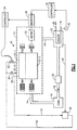
- Figure 1 is a schematic diagram of a closed refrigeration or air conditioning system employing the present invention; and
- Figure 2 is a schematic diagram of a closed refrigeration or air conditioning system employing a modified embodiment of the present invention.
-
- In figure 1, the
numeral 10 generally designates a closed refrigeration or air conditioning system. As is conventional, there is a closed circuit serially includingcompressor 12,discharge line 14 connected to the discharge port,condenser 16,line 18 which containsexpansion device 20, cooler orevaporator 22 andsuction line 24 leading to the suction port.Compressor 12 is a multi-rotor, hermetic, screw compressor.Compressor 12 is driven byelectric motor 26 which is under the control ofinverter 28 through microprocessor orcontroller 30. - An oil-rich layer forms an upper layer in
cooler 22 and is used for lubricating and sealing the rotors 12-2 and 12-2. The lubricant is drawn fromcooler 22 and supplied vialine 40 toejector 50 which is sized to supply the maximum required amount of lubricant. Line 52 supplies refrigerant gas at last closed lobe pressure toejector 50 causing the oil in a refrigerant oil mixture to be drawn fromcooler 22 vialine 40 and to be supplied tocompressor 12 for lubricating and sealing the rotors 12-1 and 12-2.Line 52 branches downstream ofejector 50 into lines 52-1 and 52-2. Line 52-1 contains arestriction 60 sized to provide the proper lubricant flow to the rotors 12-1 and 12-2 during full load conditions. Line 52-2 contains a normally closedsolenoid valve 62 and is under the control of controller ormicroprocessor 34 responsive to the speed ofmotor 26 via the output ofinverter 28.Microprocessor 30 receives temperature inputs fromthermal sensor 32 which senses the outlet chilled water temperature and responsive thereto controls inverter 28, and therebycompressor 12. When the motor speed has been reduced sufficiently,solenoid valve 62 is opened bycontroller 34 to permit more oil to be supplied to the rotors 12-1 and 12-2 for sealing and lubrication. Typically, the motor sped would be 50-60% of the full load speed whensolenoid valve 62 is opened. - Referring now to Figure 2, system 10' differs from
system 10 in dividingline 40 and replacingejector 50 with two smaller ejectors, 50-1 and 50-2, in parallel. Specifically,line 40 divides into lines 40-1 and 40-2 which are connected to ejectors 50-1 and 50-2, respectively.Line 52 divides into lines 52-1 and 52-2 which recombine intoline 52 after supplying refrigerant gas at last closed lobe pressure to ejectors 50-1 and 50-2, respectively. Ejector 50-1 is sized such that the oil refrigerant mixture drawn fromcooler 22 via line 40-1 is the proper amount to provide sealing and lubrication of rotors 12-1 and 12-2 at full load. Line 52-2 contains normally closedsolenoid valve 62 in addition to ejector 50-2. When the speed ofmotor 26 has been sufficiently reduced byinverter 28 under control ofcontroller 30,solenoid valve 62 is opened bycontroller 34 to permit more oil to be supplied to the rotors 12-1 and 12-2 for sealing and lubrication. Typically, the motor speed would be 50-60% of the full load speed whensolenoid valve 62 is opened. - Although preferred embodiments of the present invention have been illustrated and described, other changes will occur to those skilled in the art.
Claims (4)
- A closed refrigeration system containing refrigerant and oil and serially including a variable speed screw compressor having a plurality of rotors, a suction port and a discharge port and driven by a motor, a discharge line extending from said discharge port to a condenser, an expansion device, a cooler and a suction line connected to said suction port, the improvement comprising:means for pumping;a lubrication distribution system connected to said means for pumping;means for supplying an oil rich mixture from said cooler to means for pumping;means for causing said means for pumping to supply said oil rich mixture at a first rate to said lubrication distribution system for sealing and lubricating said rotors when said compressor is operating at full load and at a second, greater rate when said compressor is operating at part load.
- The closed refrigeration system of claim 1 wherein said means for pumping is an ejector pump and said means for causing supplies high pressure refrigerant to said ejector pump at last closed lobe pressure.
- The closed refrigeration system of claim 2 further including:a second ejector pump;means for supplying high pressure refrigerant to said second ejector pump;said second ejector pump being operatively connected to said cooler;means connected to said second ejector pump for supplying a refrigerant-oil mixture drawn from said cooler to said rotors for lubrication and sealing when high pressure refrigerant is supplied to said second ejector pump.
- In a closed refrigeration system containing refrigerant and oil and serially including a variable speed screw compressor having a plurality of rotors, a suction port and a discharge port and driven by a motor, a discharge line extending from said discharge port to a condenser, an expansion device, a cooler and a suction line connected to said suction port, the improvement comprising the method of improving part load performance comprising the steps of:supplying lubricant to the rotors at a first rate for lubrication and sealing when said compressor is fully loaded;supplying lubricant to the rotors at a second rate, greater then said first rate, for lubrication and sealing when said compressor is less then 60% loaded.
Applications Claiming Priority (2)
| Application Number | Priority Date | Filing Date | Title |
|---|---|---|---|
| US405120 | 1999-09-27 | ||
| US09/405,120 US6216474B1 (en) | 1999-09-27 | 1999-09-27 | Part load performance of variable speed screw compressor |
Publications (2)
| Publication Number | Publication Date |
|---|---|
| EP1087185A1 true EP1087185A1 (en) | 2001-03-28 |
| EP1087185B1 EP1087185B1 (en) | 2003-11-26 |
Family
ID=23602356
Family Applications (1)
| Application Number | Title | Priority Date | Filing Date |
|---|---|---|---|
| EP00307734A Expired - Lifetime EP1087185B1 (en) | 1999-09-27 | 2000-09-07 | Improved part load performance of variable speed screw compressor |
Country Status (8)
| Country | Link |
|---|---|
| US (1) | US6216474B1 (en) |
| EP (1) | EP1087185B1 (en) |
| JP (1) | JP3889213B2 (en) |
| KR (1) | KR100353784B1 (en) |
| CN (1) | CN100334409C (en) |
| BR (1) | BR0004482A (en) |
| DE (1) | DE60006761T2 (en) |
| ES (1) | ES2206144T3 (en) |
Cited By (5)
| Publication number | Priority date | Publication date | Assignee | Title |
|---|---|---|---|---|
| EP1273856A3 (en) * | 2001-07-02 | 2003-06-25 | Carrier Corporation | Variable speed drive chiller system |
| WO2003067092A1 (en) * | 2002-02-08 | 2003-08-14 | Atlas Copco Airpower, Naamloze Vennootschap | Method for controlling the oil recirculation in an oil-injected screw-type compressor and compressor using this method |
| EP1361364A3 (en) * | 2002-05-08 | 2004-04-14 | Carrier Corporation | Multi-rotor screw compressor |
| WO2007076213A1 (en) * | 2005-12-23 | 2007-07-05 | Gardner Denver, Inc. | Screw compressor with oil feed system |
| WO2011110475A3 (en) * | 2010-03-08 | 2012-07-26 | Bitzer Kühlmaschinenbau Gmbh | Screw-type compressor |
Families Citing this family (30)
| Publication number | Priority date | Publication date | Assignee | Title |
|---|---|---|---|---|
| JP2004104895A (en) * | 2002-09-09 | 2004-04-02 | Hitachi Ltd | Compressor drive device and refrigeration air conditioner |
| JP3629587B2 (en) | 2000-02-14 | 2005-03-16 | 株式会社日立製作所 | Air conditioner, outdoor unit and refrigeration system |
| US6550258B1 (en) * | 2000-11-22 | 2003-04-22 | Carrier Corporation | Pre-start bearing lubrication for refrigeration system compressor |
| US6739147B1 (en) * | 2002-11-27 | 2004-05-25 | Carrier Corporation | Alternate flow of discharge gas to a vaporizer for a screw compressor |
| US6672102B1 (en) | 2002-11-27 | 2004-01-06 | Carrier Corporation | Oil recovery and lubrication system for screw compressor refrigeration machine |
| US20040112679A1 (en) * | 2002-12-13 | 2004-06-17 | Centers Steven D. | System and method for lubricant flow control in a variable speed compressor package |
| US6955705B1 (en) * | 2004-06-02 | 2005-10-18 | Rdc Research Llc | Method and system for compressing and dehydrating wet natural gas produced from low-pressure wells |
| US7104076B2 (en) * | 2004-06-24 | 2006-09-12 | Carrier Corporation | Lubricant return schemes for use in refrigerant cycle |
| GB2463821B (en) * | 2005-05-17 | 2010-06-09 | Thomas Industries Inc | Pump improvements |
| US20070132330A1 (en) * | 2005-12-12 | 2007-06-14 | Fei Renyan W | Fan assemblies employing LSPM motors and LSPM motors having improved synchronization |
| JP5033351B2 (en) * | 2006-05-10 | 2012-09-26 | 日立アプライアンス株式会社 | Hermetic compressor for refrigerant |
| US8163680B2 (en) * | 2006-09-28 | 2012-04-24 | Chevron Oronite Company Llc | Method of demulsing a natural gas dehydrator |
| JP5373335B2 (en) * | 2008-08-08 | 2013-12-18 | 株式会社神戸製鋼所 | Refrigeration equipment |
| US10941770B2 (en) | 2010-07-20 | 2021-03-09 | Trane International Inc. | Variable capacity screw compressor and method |
| CN101949619B (en) * | 2010-08-31 | 2012-10-10 | 广东美的电器股份有限公司 | Lubricating oil and refrigerant separation device of refrigerating unit and operating method thereof |
| CN103229007B (en) | 2010-11-30 | 2016-06-15 | 开利公司 | Injector circulates |
| WO2014158329A1 (en) * | 2013-03-25 | 2014-10-02 | Carrier Corporation | Compressor bearing cooling |
| CN105393066B (en) * | 2013-05-03 | 2017-08-08 | 特灵空调系统(中国)有限公司 | Oil return control in HAVC system |
| US10309698B2 (en) | 2013-05-03 | 2019-06-04 | Trane International Inc. | Oil return management in a HVAC system |
| WO2016180481A1 (en) | 2015-05-12 | 2016-11-17 | Carrier Corporation | Ejector refrigeration circuit |
| DE102015111287B4 (en) * | 2015-07-13 | 2018-04-26 | Gardner Denver Deutschland Gmbh | Compressor and method for its speed control |
| US10473377B2 (en) | 2016-09-26 | 2019-11-12 | Carrier Corporation | High outdoor ambient and high suction pressure oil pump out mitigation for air conditioners |
| EP3658774B1 (en) | 2017-07-28 | 2021-07-07 | Carrier Corporation | Lubrication supply system |
| CN111373213B (en) | 2017-09-25 | 2022-04-05 | 江森自控科技公司 | Two stage oil powered injector system |
| BR102018071557A2 (en) * | 2018-10-19 | 2020-04-28 | Tecumseh Do Brasil Ltda. | method to increase the efficiency of hermetic compressors applied in refrigeration and air conditioners. |
| US11982475B2 (en) | 2019-05-07 | 2024-05-14 | Carrier Corporation | Refrigerant lubrication system with side channel pump |
| CN111608900B (en) * | 2020-05-29 | 2024-02-20 | 宁波鲍斯能源装备股份有限公司 | Variable-rotation-speed screw air compressor testing system and method |
| CN214741982U (en) * | 2020-12-09 | 2021-11-16 | 明达实业(厦门)有限公司 | A kind of air pump pressure regulation speed regulation control circuit |
| CN112984880B (en) * | 2021-03-04 | 2022-03-01 | 珠海格力电器股份有限公司 | Method and device for adjusting oil supply amount of compressor, computer equipment and storage medium |
| KR102693613B1 (en) * | 2022-07-13 | 2024-08-09 | 범천 주식회사 | Compressed air production system using screw compressor |
Citations (6)
| Publication number | Priority date | Publication date | Assignee | Title |
|---|---|---|---|---|
| US2975613A (en) * | 1959-01-23 | 1961-03-21 | Gen Motors Corp | Refrigerating apparatus with aspirator in a by-pass |
| US3150277A (en) * | 1962-03-14 | 1964-09-22 | Worthington Corp | Hermetic motor cooling by liquid refrigerant |
| US4351160A (en) * | 1980-06-16 | 1982-09-28 | Borg-Warner Corporation | Capacity control systems for screw compressor based water chillers |
| EP0531248A1 (en) * | 1991-09-03 | 1993-03-10 | Carrier Corporation | Oil reclaim in a centrifugal chiller system |
| US5761914A (en) * | 1997-02-18 | 1998-06-09 | American Standard Inc. | Oil return from evaporator to compressor in a refrigeration system |
| WO1999013299A2 (en) * | 1997-09-05 | 1999-03-18 | American Standard Inc. | Liquid level sensor |
Family Cites Families (6)
| Publication number | Priority date | Publication date | Assignee | Title |
|---|---|---|---|---|
| US4503685A (en) * | 1982-11-19 | 1985-03-12 | Hussmann Corporation | Oil control valve for refrigeration system |
| US4662190A (en) * | 1985-12-10 | 1987-05-05 | Tischer James C | Integral slide valve-oil separator apparatus in a screw compressor |
| US5634345A (en) * | 1995-06-06 | 1997-06-03 | Alsenz; Richard H. | Oil monitoring system |
| US5603227A (en) * | 1995-11-13 | 1997-02-18 | Carrier Corporation | Back pressure control for improved system operative efficiency |
| JPH10131889A (en) * | 1996-10-25 | 1998-05-19 | Mitsubishi Heavy Ind Ltd | Compressor for perforator |
| JP3640749B2 (en) * | 1996-12-19 | 2005-04-20 | シャープ株式会社 | Refrigeration cycle of air conditioner |
-
1999
- 1999-09-27 US US09/405,120 patent/US6216474B1/en not_active Expired - Fee Related
-
2000
- 2000-09-07 DE DE60006761T patent/DE60006761T2/en not_active Expired - Lifetime
- 2000-09-07 ES ES00307734T patent/ES2206144T3/en not_active Expired - Lifetime
- 2000-09-07 EP EP00307734A patent/EP1087185B1/en not_active Expired - Lifetime
- 2000-09-26 KR KR1020000056328A patent/KR100353784B1/en not_active Expired - Fee Related
- 2000-09-27 JP JP2000293378A patent/JP3889213B2/en not_active Expired - Fee Related
- 2000-09-27 CN CNB001305808A patent/CN100334409C/en not_active Expired - Fee Related
- 2000-09-27 BR BR0004482-2A patent/BR0004482A/en not_active IP Right Cessation
Patent Citations (6)
| Publication number | Priority date | Publication date | Assignee | Title |
|---|---|---|---|---|
| US2975613A (en) * | 1959-01-23 | 1961-03-21 | Gen Motors Corp | Refrigerating apparatus with aspirator in a by-pass |
| US3150277A (en) * | 1962-03-14 | 1964-09-22 | Worthington Corp | Hermetic motor cooling by liquid refrigerant |
| US4351160A (en) * | 1980-06-16 | 1982-09-28 | Borg-Warner Corporation | Capacity control systems for screw compressor based water chillers |
| EP0531248A1 (en) * | 1991-09-03 | 1993-03-10 | Carrier Corporation | Oil reclaim in a centrifugal chiller system |
| US5761914A (en) * | 1997-02-18 | 1998-06-09 | American Standard Inc. | Oil return from evaporator to compressor in a refrigeration system |
| WO1999013299A2 (en) * | 1997-09-05 | 1999-03-18 | American Standard Inc. | Liquid level sensor |
Cited By (14)
| Publication number | Priority date | Publication date | Assignee | Title |
|---|---|---|---|---|
| EP1273856A3 (en) * | 2001-07-02 | 2003-06-25 | Carrier Corporation | Variable speed drive chiller system |
| AU784596B2 (en) * | 2001-07-02 | 2006-05-11 | Carrier Corporation | Variable speed drive chiller system |
| KR100758569B1 (en) * | 2002-02-08 | 2007-09-14 | 아틀라스 캅코 에어파워, 남로체 벤누트삽 | Method for controlling oil recirculation in lubricated screw compressors and compressors using the method |
| WO2003067092A1 (en) * | 2002-02-08 | 2003-08-14 | Atlas Copco Airpower, Naamloze Vennootschap | Method for controlling the oil recirculation in an oil-injected screw-type compressor and compressor using this method |
| BE1014611A3 (en) * | 2002-02-08 | 2004-01-13 | Atlas Copco Airpower Nv | Method for oil return of driving in an oil injected screw compressor and thus controlled screw compressor. |
| US7204678B2 (en) | 2002-02-08 | 2007-04-17 | Atlas Copco Airpower, Naamloze Vennootschap | Method for controlling the oil recirculation in an oil-injected screw-type compressor and compressor using this method |
| CN100362241C (en) * | 2002-02-08 | 2008-01-16 | 艾拉斯科普库空气动力股份有限公司 | Method for controlling oil circulation in oil-injected screw compressor and compressor using the method |
| EP1722105A3 (en) * | 2002-05-08 | 2008-04-23 | Carrier Corporation | Multi-rotor screw compressor |
| EP1361364A3 (en) * | 2002-05-08 | 2004-04-14 | Carrier Corporation | Multi-rotor screw compressor |
| WO2007076213A1 (en) * | 2005-12-23 | 2007-07-05 | Gardner Denver, Inc. | Screw compressor with oil feed system |
| WO2011110475A3 (en) * | 2010-03-08 | 2012-07-26 | Bitzer Kühlmaschinenbau Gmbh | Screw-type compressor |
| CN102792027A (en) * | 2010-03-08 | 2012-11-21 | 比泽尔制冷设备有限公司 | Screw-type compressor |
| US8870555B2 (en) | 2010-03-08 | 2014-10-28 | Bitzer Kuehlmaschinenbau Gmbh | Screw compressor |
| CN102792027B (en) * | 2010-03-08 | 2015-05-13 | 比泽尔制冷设备有限公司 | Screw-type compressor |
Also Published As
| Publication number | Publication date |
|---|---|
| EP1087185B1 (en) | 2003-11-26 |
| JP2001132676A (en) | 2001-05-18 |
| CN100334409C (en) | 2007-08-29 |
| KR20010067229A (en) | 2001-07-12 |
| ES2206144T3 (en) | 2004-05-16 |
| JP3889213B2 (en) | 2007-03-07 |
| DE60006761T2 (en) | 2004-09-30 |
| KR100353784B1 (en) | 2002-09-27 |
| DE60006761D1 (en) | 2004-01-08 |
| CN1289896A (en) | 2001-04-04 |
| BR0004482A (en) | 2001-04-10 |
| US6216474B1 (en) | 2001-04-17 |
Similar Documents
| Publication | Publication Date | Title |
|---|---|---|
| EP1087185B1 (en) | Improved part load performance of variable speed screw compressor | |
| CN1091510C (en) | Capacity control for multi-stage compressors | |
| CN101218433B (en) | Oil supply method and device for two-stage screw compressor, and method of operating refrigeration device | |
| US3961862A (en) | Compressor control system | |
| US4180986A (en) | Refrigeration system on/off cycle | |
| EP1941219B1 (en) | Refrigerant system with pulse width modulated components and variable speed compressor | |
| US8122735B2 (en) | Refrigerating apparatus | |
| EP1087190B1 (en) | Lubrication system for screw compressors using an oil still | |
| US8312732B2 (en) | Refrigerating apparatus | |
| EP2012075A1 (en) | Refrigeration device | |
| US11994321B2 (en) | High performance compressors and vapor compression systems | |
| JPH02140477A (en) | two stage compressor | |
| CN117190518A (en) | Refrigerating system | |
| KR20110074708A (en) | Freezing device | |
| JP7554254B2 (en) | Helium compressor system with unmodified scroll compressor | |
| JPH11351168A (en) | Screw type refrigerating device | |
| CN104075475B (en) | Turborefrigerator | |
| CN101523129B (en) | Refrigerant system and method for operating refrigerant system | |
| JP2000337282A (en) | Two-stage type screw compressor | |
| CN117090773A (en) | An improved helium compressor using an air conditioning scroll pressure pack with enthalpy increasing function | |
| JPH0583666U (en) | Refrigeration equipment | |
| CN219199534U (en) | Oilless cascade refrigeration system | |
| CN120740236A (en) | Compressor oil supply control method and control system and air conditioning unit | |
| JPH11281181A (en) | Cold storage chiller | |
| JPH11303785A (en) | Oil-cooled screw compressor for forced gas feeding |
Legal Events
| Date | Code | Title | Description |
|---|---|---|---|
| PUAI | Public reference made under article 153(3) epc to a published international application that has entered the european phase |
Free format text: ORIGINAL CODE: 0009012 |
|
| AK | Designated contracting states |
Kind code of ref document: A1 Designated state(s): DE ES FR GB IT SE |
|
| AX | Request for extension of the european patent |
Free format text: AL;LT;LV;MK;RO;SI |
|
| 17P | Request for examination filed |
Effective date: 20010406 |
|
| AKX | Designation fees paid |
Free format text: DE ES FR GB IT SE |
|
| 17Q | First examination report despatched |
Effective date: 20020307 |
|
| GRAH | Despatch of communication of intention to grant a patent |
Free format text: ORIGINAL CODE: EPIDOS IGRA |
|
| GRAS | Grant fee paid |
Free format text: ORIGINAL CODE: EPIDOSNIGR3 |
|
| GRAA | (expected) grant |
Free format text: ORIGINAL CODE: 0009210 |
|
| AK | Designated contracting states |
Kind code of ref document: B1 Designated state(s): DE ES FR GB IT SE |
|
| REG | Reference to a national code |
Ref country code: GB Ref legal event code: FG4D |
|
| REG | Reference to a national code |
Ref country code: SE Ref legal event code: TRGR |
|
| REF | Corresponds to: |
Ref document number: 60006761 Country of ref document: DE Date of ref document: 20040108 Kind code of ref document: P |
|
| REG | Reference to a national code |
Ref country code: ES Ref legal event code: FG2A Ref document number: 2206144 Country of ref document: ES Kind code of ref document: T3 |
|
| ET | Fr: translation filed | ||
| PLBE | No opposition filed within time limit |
Free format text: ORIGINAL CODE: 0009261 |
|
| STAA | Information on the status of an ep patent application or granted ep patent |
Free format text: STATUS: NO OPPOSITION FILED WITHIN TIME LIMIT |
|
| 26N | No opposition filed |
Effective date: 20040827 |
|
| PGFP | Annual fee paid to national office [announced via postgrant information from national office to epo] |
Ref country code: SE Payment date: 20070905 Year of fee payment: 8 |
|
| PG25 | Lapsed in a contracting state [announced via postgrant information from national office to epo] |
Ref country code: SE Free format text: LAPSE BECAUSE OF NON-PAYMENT OF DUE FEES Effective date: 20080908 |
|
| PGFP | Annual fee paid to national office [announced via postgrant information from national office to epo] |
Ref country code: GB Payment date: 20100901 Year of fee payment: 11 |
|
| PGFP | Annual fee paid to national office [announced via postgrant information from national office to epo] |
Ref country code: ES Payment date: 20101018 Year of fee payment: 11 |
|
| GBPC | Gb: european patent ceased through non-payment of renewal fee |
Effective date: 20110907 |
|
| PG25 | Lapsed in a contracting state [announced via postgrant information from national office to epo] |
Ref country code: GB Free format text: LAPSE BECAUSE OF NON-PAYMENT OF DUE FEES Effective date: 20110907 |
|
| PGFP | Annual fee paid to national office [announced via postgrant information from national office to epo] |
Ref country code: IT Payment date: 20120914 Year of fee payment: 13 |
|
| REG | Reference to a national code |
Ref country code: ES Ref legal event code: FD2A Effective date: 20130530 |
|
| PG25 | Lapsed in a contracting state [announced via postgrant information from national office to epo] |
Ref country code: ES Free format text: LAPSE BECAUSE OF NON-PAYMENT OF DUE FEES Effective date: 20110908 |
|
| PG25 | Lapsed in a contracting state [announced via postgrant information from national office to epo] |
Ref country code: IT Free format text: LAPSE BECAUSE OF NON-PAYMENT OF DUE FEES Effective date: 20130907 |
|
| PGFP | Annual fee paid to national office [announced via postgrant information from national office to epo] |
Ref country code: DE Payment date: 20140903 Year of fee payment: 15 |
|
| REG | Reference to a national code |
Ref country code: FR Ref legal event code: PLFP Year of fee payment: 16 |
|
| PGFP | Annual fee paid to national office [announced via postgrant information from national office to epo] |
Ref country code: FR Payment date: 20150824 Year of fee payment: 16 |
|
| REG | Reference to a national code |
Ref country code: DE Ref legal event code: R119 Ref document number: 60006761 Country of ref document: DE |
|
| PG25 | Lapsed in a contracting state [announced via postgrant information from national office to epo] |
Ref country code: DE Free format text: LAPSE BECAUSE OF NON-PAYMENT OF DUE FEES Effective date: 20160401 |
|
| REG | Reference to a national code |
Ref country code: FR Ref legal event code: ST Effective date: 20170531 |
|
| PG25 | Lapsed in a contracting state [announced via postgrant information from national office to epo] |
Ref country code: FR Free format text: LAPSE BECAUSE OF NON-PAYMENT OF DUE FEES Effective date: 20160930 |