EP1087145A2 - Centrifugal pump - Google Patents
Centrifugal pump Download PDFInfo
- Publication number
- EP1087145A2 EP1087145A2 EP00308247A EP00308247A EP1087145A2 EP 1087145 A2 EP1087145 A2 EP 1087145A2 EP 00308247 A EP00308247 A EP 00308247A EP 00308247 A EP00308247 A EP 00308247A EP 1087145 A2 EP1087145 A2 EP 1087145A2
- Authority
- EP
- European Patent Office
- Prior art keywords
- impeller
- fluid
- shroud
- centrifugal pump
- outlet
- Prior art date
- Legal status (The legal status is an assumption and is not a legal conclusion. Google has not performed a legal analysis and makes no representation as to the accuracy of the status listed.)
- Withdrawn
Links
- 239000012530 fluid Substances 0.000 claims abstract description 30
- 238000005086 pumping Methods 0.000 claims abstract description 17
- 230000002093 peripheral effect Effects 0.000 claims abstract description 9
- 238000000926 separation method Methods 0.000 claims description 3
- 230000000712 assembly Effects 0.000 description 1
- 238000000429 assembly Methods 0.000 description 1
- 238000011084 recovery Methods 0.000 description 1
- 230000003068 static effect Effects 0.000 description 1
Images
Classifications
-
- F—MECHANICAL ENGINEERING; LIGHTING; HEATING; WEAPONS; BLASTING
- F04—POSITIVE - DISPLACEMENT MACHINES FOR LIQUIDS; PUMPS FOR LIQUIDS OR ELASTIC FLUIDS
- F04D—NON-POSITIVE-DISPLACEMENT PUMPS
- F04D29/00—Details, component parts, or accessories
- F04D29/18—Rotors
- F04D29/22—Rotors specially for centrifugal pumps
- F04D29/2238—Special flow patterns
- F04D29/2255—Special flow patterns flow-channels with a special cross-section contour, e.g. ejecting, throttling or diffusing effect
-
- F—MECHANICAL ENGINEERING; LIGHTING; HEATING; WEAPONS; BLASTING
- F04—POSITIVE - DISPLACEMENT MACHINES FOR LIQUIDS; PUMPS FOR LIQUIDS OR ELASTIC FLUIDS
- F04D—NON-POSITIVE-DISPLACEMENT PUMPS
- F04D1/00—Radial-flow pumps, e.g. centrifugal pumps; Helico-centrifugal pumps
- F04D1/06—Multi-stage pumps
-
- F—MECHANICAL ENGINEERING; LIGHTING; HEATING; WEAPONS; BLASTING
- F04—POSITIVE - DISPLACEMENT MACHINES FOR LIQUIDS; PUMPS FOR LIQUIDS OR ELASTIC FLUIDS
- F04D—NON-POSITIVE-DISPLACEMENT PUMPS
- F04D29/00—Details, component parts, or accessories
- F04D29/40—Casings; Connections of working fluid
- F04D29/42—Casings; Connections of working fluid for radial or helico-centrifugal pumps
- F04D29/44—Fluid-guiding means, e.g. diffusers
- F04D29/445—Fluid-guiding means, e.g. diffusers especially adapted for liquid pumps
Definitions
- the present invention relates to a centrifugal pump having at least one pumping assembly including an impeller to drive a fluid in an outward direction and a diffuser located opposite to the impeller and having passages to direct the fluid both inwardly and axially towards an outlet passage.
- Centrifugal pumps may be used to pump a variety of fluids.
- a pump includes one or more pumping stages located between an inlet and outlet.
- Each of the pumping stages has an impeller to impart a high velocity to the fluid and a diffuser assembly located opposite to the impeller to recovery the static pressure lost at high fluid velocities.
- Examples of centrifugal pump designs can be found in US-A-5,344,285, US-A-5,938,661, US-A-5,732,803, and US-A-3,986,791.
- rotating impellers having vanes impart a high kinetic energy to the fluid flow. The fluid after having been accelerated then passes into channels that require the fluid to turn approximately 90° to enter the diffuser and then in some designs, turn another 90° to enter to enter the next pumping stage.
- the present invention aims at providing a pump that has relatively low energy losses as a result of changes in the direction of fluid flow.
- the present invention provides a centrifugal pump.
- a pump body is provided having opposed inlet and outlet passages.
- a drive shaft is located (ie received) within the pump body and at least one pumping stage is located between the inlet and outlet passages.
- the or each pumping stage has an impeller connected to the drive shaft and is provided with a central portion, an outer circular periphery, and rotor vanes radiating from the central portion to drive the fluid to be pumped in a direction taken from the central portion to the outer circular periphery through rotation of the impeller by the drive shaft.
- a shroud is connected to the impeller for rotation therewith.
- the shroud has an outer peripheral portion extending beyond the outer circular periphery of the impeller in an overlapping relationship and is configured to deflect the fluid towards the outlet passage.
- a diffuser is located opposite to the impeller and has a stator assembly including passages configured to centrally and axially deflect the fluid from the outer peripheral portion of the shroud towards the outlet passage.
- the rotor vanes outwardly spiral to the circular outer periphery of the impeller.
- Each of the passages of the diffuser may advantageously inwardly spiral in a transverse direction of the pump to centrally direct the fluid so that it curves in an axial direction and turns inwardly at an obtuse angle.
- the shroud can be provided with an upright-ring-like inlet section for intake of fluid into the impeller.
- intermediate splitter vanes may be provided to prevent separation of flow.
- the vanes extend into an overlap defined between the shroud and the circular outer periphery of the impeller.
- Centrifugal pump 1 in accordance with the present invention is illustrated.
- Centrifugal pump 1 is provided with a pump body 10 and one or more pumping stages such as 12 and 14.
- Each of the pumping stages includes an impeller assembly 16 driven by a drive shaft 18 and a diffuser 20.
- a fluid enters pump body 10 through an inlet 22 and is then directed to pumping stage 12 preferably by inlet vanes 23 in a conventional manner. Fluid A is then pressurised by pumping stages 12 and 14 and discharged from an outlet 24 located opposite inlet 22.
- impeller assembly 16 is provided with an impeller 26 having rotor vanes 28 that radiate from a central portion 30 of impeller 26 to an outer circular periphery 32.
- the rotor blades spiral and include main rotor vanes 34 and intermediate splitter vanes 36.
- the intermediate splitter vanes 36 reduce separation.
- each impeller 16 is provided with a shroud 38 connected to or integral with impeller 26 for rotation therewith.
- Shroud 38 has an outer forwardly curved peripheral portion 40 that extends beyond the outer circular periphery 32 of impeller 26.
- shroud 38 can be provided with an upright ring-like section 44 for intake of fluid into impeller assembly 16.
- Diffuser 20 has passages 46 formed between upper and lower sections 48 and 50 thereof. Referring to Figure 4, upper section 48 has been removed to show passages 46. As illustrated, passages 46 spirals inwardly to an outlet portion 52. Additionally, as can best be seen in Figure 1, each of the passages 46 curves inwardly in an axial direction and thereby turns inwardly at an obtuse angle to minimise losses. Such obtuse angle can be defined as the angle between two intersecting tangents to each of passages 46 at opposite ends thereof.
- Drive shaft 18 which is driven by a motor (not shown), is attached to impeller assembly(s) 16 preferably by a keyed connection.
- Drive shaft 18 rides within a bearing sleeve 54 connected to diffuser 20 so as to be able to turn within diffuser 20.
- a seal is effected between each impeller assembly 16 and each diffuser 20 by way of a labyrinth seal 56 that contacts a sleeve-like element 58 connected to impeller assembly 16 so as to depend therefrom.
- Drive shaft 18 is provided with a hexagonal 60 to hold drive shaft 18 in place.
- a bearing 62 is provided to allow the drive shaft 18 to turn with respect to a lowermost of diffusers 20.
- Pump body 10 has a conventional cylindrical sidewall 64 into which pumping assemblies such as 12 and 14 are fitted. Impellers 16 are held in position by their connection to drive shaft 18. Diffusers are supported within cylindrical sidewall 64 between end spacing elements 68 and 70 by intermediate spacing elements 72. End spacing element 68 is fitted within an end cap 74 connected to cylindrical sidewall 64. End spacing element 70 is connected to cylindrical sidewall 64.
Landscapes
- Engineering & Computer Science (AREA)
- Mechanical Engineering (AREA)
- General Engineering & Computer Science (AREA)
- Structures Of Non-Positive Displacement Pumps (AREA)
Abstract
Description
- The present invention relates to a centrifugal pump having at least one pumping assembly including an impeller to drive a fluid in an outward direction and a diffuser located opposite to the impeller and having passages to direct the fluid both inwardly and axially towards an outlet passage.
- Centrifugal pumps may be used to pump a variety of fluids. Generally, such a pump includes one or more pumping stages located between an inlet and outlet. Each of the pumping stages has an impeller to impart a high velocity to the fluid and a diffuser assembly located opposite to the impeller to recovery the static pressure lost at high fluid velocities. Examples of centrifugal pump designs can be found in US-A-5,344,285, US-A-5,938,661, US-A-5,732,803, and US-A-3,986,791. In all of these patents, there are disclosed rotating impellers having vanes impart a high kinetic energy to the fluid flow. The fluid after having been accelerated then passes into channels that require the fluid to turn approximately 90° to enter the diffuser and then in some designs, turn another 90° to enter to enter the next pumping stage.
- Energy losses occur at each turn of fluid direction and such losses decrease pumping efficiency. The present invention aims at providing a pump that has relatively low energy losses as a result of changes in the direction of fluid flow.
- The present invention provides a centrifugal pump. In accordance with the present invention a pump body is provided having opposed inlet and outlet passages. A drive shaft is located (ie received) within the pump body and at least one pumping stage is located between the inlet and outlet passages. The or each pumping stage has an impeller connected to the drive shaft and is provided with a central portion, an outer circular periphery, and rotor vanes radiating from the central portion to drive the fluid to be pumped in a direction taken from the central portion to the outer circular periphery through rotation of the impeller by the drive shaft. A shroud is connected to the impeller for rotation therewith. The shroud has an outer peripheral portion extending beyond the outer circular periphery of the impeller in an overlapping relationship and is configured to deflect the fluid towards the outlet passage. A diffuser is located opposite to the impeller and has a stator assembly including passages configured to centrally and axially deflect the fluid from the outer peripheral portion of the shroud towards the outlet passage.
- It has been found by the inventors herein that by so shrouding the impeller and changing the direction of flow at the impeller rather than through passages in a pump fewer frictional losses will occur to increase the efficiency of the pump of the present invention.
- Preferably, the rotor vanes outwardly spiral to the circular outer periphery of the impeller. Each of the passages of the diffuser may advantageously inwardly spiral in a transverse direction of the pump to centrally direct the fluid so that it curves in an axial direction and turns inwardly at an obtuse angle. Such design feature allows losses to be further reduced. Additionally, the shroud can be provided with an upright-ring-like inlet section for intake of fluid into the impeller. In this regard, intermediate splitter vanes may be provided to prevent separation of flow. Preferably, the vanes extend into an overlap defined between the shroud and the circular outer periphery of the impeller.
- The invention will now be described with reference to:
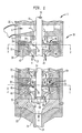
- Figure 1 is a sectional view of a centrifugal pump in accordance with the present invention;
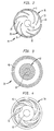
- Figure 2 is a sectional view taken along line 2-2 of Figure 1;
- Figure 3 is a sectional view taken along line 3-3 of Figure 1; and
- Figure 4 is a top sectional view of a diffuser in accordance with the present invention in which sections have been removed to show its passages.
-
- With reference to Figure 1, a
centrifugal pump 1 in accordance with the present invention is illustrated.Centrifugal pump 1 is provided with apump body 10 and one or more pumping stages such as 12 and 14. Each of the pumping stages includes animpeller assembly 16 driven by adrive shaft 18 and adiffuser 20. As indicated by arrowheads "A", a fluid enterspump body 10 through aninlet 22 and is then directed to pumpingstage 12 preferably byinlet vanes 23 in a conventional manner. Fluid A is then pressurised by pumpingstages outlet 24 located oppositeinlet 22. - With additional reference to Figure 2,
impeller assembly 16 is provided with animpeller 26 havingrotor vanes 28 that radiate from acentral portion 30 ofimpeller 26 to an outercircular periphery 32. Preferably the rotor blades spiral and includemain rotor vanes 34 andintermediate splitter vanes 36. The intermediate splitter vanes 36 reduce separation. Additionally, eachimpeller 16 is provided with ashroud 38 connected to or integral withimpeller 26 for rotation therewith. Shroud 38 has an outer forwardly curvedperipheral portion 40 that extends beyond the outercircular periphery 32 ofimpeller 26. Fluid A moves outwardly to outercircular periphery 32 fromcentral portion 30 and then is deflected intooverlap 42 formed between outerperipheral portion 40 ofshroud 38 and outercircular periphery 32 ofimpeller 26. Preferably as an intake,shroud 38 can be provided with an upright ring-like section 44 for intake of fluid intoimpeller assembly 16. - With additional reference to Fig 3, the pressure of the fluid is recovered within
diffuser 20. Diffuser 20 haspassages 46 formed between upper andlower sections upper section 48 has been removed to showpassages 46. As illustrated,passages 46 spirals inwardly to anoutlet portion 52. Additionally, as can best be seen in Figure 1, each of thepassages 46 curves inwardly in an axial direction and thereby turns inwardly at an obtuse angle to minimise losses. Such obtuse angle can be defined as the angle between two intersecting tangents to each ofpassages 46 at opposite ends thereof. -
Drive shaft 18 which is driven by a motor (not shown), is attached to impeller assembly(s) 16 preferably by a keyed connection.Drive shaft 18 rides within abearing sleeve 54 connected todiffuser 20 so as to be able to turn withindiffuser 20. A seal is effected between eachimpeller assembly 16 and eachdiffuser 20 by way of alabyrinth seal 56 that contacts a sleeve-like element 58 connected toimpeller assembly 16 so as to depend therefrom.Drive shaft 18 is provided with a hexagonal 60 to holddrive shaft 18 in place. Abearing 62 is provided to allow thedrive shaft 18 to turn with respect to a lowermost ofdiffusers 20. -
Pump body 10 has a conventionalcylindrical sidewall 64 into which pumping assemblies such as 12 and 14 are fitted.Impellers 16 are held in position by their connection to driveshaft 18. Diffusers are supported withincylindrical sidewall 64 betweenend spacing elements intermediate spacing elements 72.End spacing element 68 is fitted within anend cap 74 connected tocylindrical sidewall 64.End spacing element 70 is connected tocylindrical sidewall 64.
Claims (7)
- A centrifugal pump comprising:a pump body having opposed inlet and outlet passages;a drive shaft located within said pump body; andat least one pumping assembly located between said inlet and outlet passages and having,an impeller connected to said drive shaft and having a central portion, an outer circular periphery, and rotor vanes radiating from said central portion to drive a fluid to be pumped in a direction taken from the central portion to said outer circular periphery through rotation of said impeller by said drive shaft,a shroud connected to said impeller for rotation therewith, said shroud having an outer peripheral portion extending beyond the outer circular periphery of said impeller in an overlapping relationship and configured to deflect said fluid toward said outlet passage, anda diffuser located opposite said impeller and having a stator assembly including passages configured to centrally and axially direct said fluid from said outer peripheral portion of said shroud towards said outlet passage.
- A centrifugal pump according to claim 1, wherein said rotor vanes spiral outwards to said outer circular periphery.
- A centrifugal pump according to claim 1 or claim 2, wherein each of said passages of said diffuser curves inwards in the direction of the outlet, the angle of curvature in sectional side elevation being obtuse.
- A centrifugal pump according to any one of the preceding claims, wherein said shroud has an upright, ring-like inlet section for intake of said fluid into said impeller.
- A centrifugal pump according to any one of the preceding claims, wherein said rotor vanes include intermediate splitter vanes to prevent separation of said flow.
- A centrifugal pump according to any one of the preceding claims, wherein said vanes extend into an overlap defined between said shroud and said circular outer periphery of said impeller.
- A centrifugal pump comprising, a pump body (10) having at least one internal pumping chamber having an axial inlet opposed to an axial outlet and housing a pumping assembly, the pumping assembly comprising:wherein the shroud (38) has an outer peripheral portion (40) extending outwardly beyond and overlapping the circular periphery (32) of the impeller (26) and having a configuration for deflecting fluid forwards in an axial direction.a) a rotary impeller (26) mounted on a drive shaft (18), the rotary impeller (26) having a central portion (30), an outer circular periphery (32), and vanes (34) radiating outwards for urging fluid radially outwards;b) a shroud (38) associated with the impeller (26) and arranged for rotation therewith; andc) a diffuser (20) having passages (46) therethrough for guiding fluid both inwards and axially forwards towards the said axial outlet;
Applications Claiming Priority (2)
| Application Number | Priority Date | Filing Date | Title |
|---|---|---|---|
| US40518499A | 1999-09-24 | 1999-09-24 | |
| US405184 | 1999-09-24 |
Publications (2)
| Publication Number | Publication Date |
|---|---|
| EP1087145A2 true EP1087145A2 (en) | 2001-03-28 |
| EP1087145A3 EP1087145A3 (en) | 2001-04-18 |
Family
ID=23602629
Family Applications (1)
| Application Number | Title | Priority Date | Filing Date |
|---|---|---|---|
| EP00308247A Withdrawn EP1087145A3 (en) | 1999-09-24 | 2000-09-21 | Centrifugal pump |
Country Status (1)
| Country | Link |
|---|---|
| EP (1) | EP1087145A3 (en) |
Cited By (1)
| Publication number | Priority date | Publication date | Assignee | Title |
|---|---|---|---|---|
| CN113503253A (en) * | 2021-06-17 | 2021-10-15 | 扬州大学 | Miniature disc pump with spiral guide vanes |
Citations (4)
| Publication number | Priority date | Publication date | Assignee | Title |
|---|---|---|---|---|
| US3986791A (en) | 1974-04-01 | 1976-10-19 | Sigma Lutin, Narodni Podnik | Hydrodynamic multi-stage pump |
| US5344285A (en) | 1993-10-04 | 1994-09-06 | Ingersoll-Dresser Pump Company | Centrifugal pump with monolithic diffuser and return vane channel ring member |
| US5732803A (en) | 1995-11-08 | 1998-03-31 | Deutsche Forschungsanstalt Fur Luft- Und Raumfahrt E.V. | Current collector for transmitting energy between a contact wire and a motor coach |
| US5938661A (en) | 1997-02-05 | 1999-08-17 | Symbosis Corporation | Single arm electrocautery probes for use with a resectoscope |
Family Cites Families (9)
| Publication number | Priority date | Publication date | Assignee | Title |
|---|---|---|---|---|
| GB297661A (en) * | 1900-01-01 | |||
| US2273420A (en) * | 1941-02-17 | 1942-02-17 | Pomona Pump Co | Centrifugal pump |
| US2857849A (en) * | 1953-11-13 | 1958-10-28 | Joseph R Smylie | Motor driven pumping units |
| US3093084A (en) * | 1961-02-21 | 1963-06-11 | Derderian George | Pump |
| US3953150A (en) * | 1972-02-10 | 1976-04-27 | Sundstrand Corporation | Impeller apparatus |
| US3779668A (en) * | 1972-05-11 | 1973-12-18 | Mcneil Corp | Stage for a centrifugal pump |
| US3837612A (en) * | 1973-06-01 | 1974-09-24 | Red Jacket Mfg Co | Mold apparatus for mixed flow impeller |
| US4802819A (en) * | 1987-09-14 | 1989-02-07 | Mcneil (Ohio) Corporation | Centrifugal pump |
| DE19607292C2 (en) * | 1996-02-27 | 2000-06-08 | Grundfos A S Bjerringbro | Housing with guide device for one pump stage of a multi-stage centrifugal pump |
-
2000
- 2000-09-21 EP EP00308247A patent/EP1087145A3/en not_active Withdrawn
Patent Citations (4)
| Publication number | Priority date | Publication date | Assignee | Title |
|---|---|---|---|---|
| US3986791A (en) | 1974-04-01 | 1976-10-19 | Sigma Lutin, Narodni Podnik | Hydrodynamic multi-stage pump |
| US5344285A (en) | 1993-10-04 | 1994-09-06 | Ingersoll-Dresser Pump Company | Centrifugal pump with monolithic diffuser and return vane channel ring member |
| US5732803A (en) | 1995-11-08 | 1998-03-31 | Deutsche Forschungsanstalt Fur Luft- Und Raumfahrt E.V. | Current collector for transmitting energy between a contact wire and a motor coach |
| US5938661A (en) | 1997-02-05 | 1999-08-17 | Symbosis Corporation | Single arm electrocautery probes for use with a resectoscope |
Cited By (1)
| Publication number | Priority date | Publication date | Assignee | Title |
|---|---|---|---|---|
| CN113503253A (en) * | 2021-06-17 | 2021-10-15 | 扬州大学 | Miniature disc pump with spiral guide vanes |
Also Published As
| Publication number | Publication date |
|---|---|
| EP1087145A3 (en) | 2001-04-18 |
Similar Documents
| Publication | Publication Date | Title |
|---|---|---|
| JP4168032B2 (en) | Turbo compressor | |
| EP3133294B1 (en) | Fan, diffuser, and vacuum cleaner having the same | |
| EP0870111B1 (en) | Pump impeller having separate offset inlet vanes | |
| US8801360B2 (en) | Centrifugal pump with thrust balance holes in diffuser | |
| EP0805275B1 (en) | Vacuum pump | |
| US6589013B2 (en) | Fluid flow controller | |
| US3967915A (en) | Centrifugal pump | |
| US6113363A (en) | Turbine fuel pump | |
| CA2404623A1 (en) | Ventricular assist system secondary impeller | |
| JPH11280686A (en) | Turbine type fuel pump | |
| KR20150070294A (en) | High efficiency low specific speed centrifugal pump | |
| US20170159669A1 (en) | Impeller, And Pump And Fluid Delivery Device Using The Impeller | |
| EP1216359B1 (en) | Centrifugal pump | |
| US6422829B1 (en) | Compound pump | |
| JP4095799B2 (en) | Fuel pump with steam vent | |
| US4655680A (en) | Continuous blade axial-flow friction drag pump | |
| JP6078303B2 (en) | Centrifugal fluid machine | |
| JP2004515696A (en) | Feed pump | |
| US4531887A (en) | Continuous blade multi-stage pump | |
| CA2142853A1 (en) | Regenerative pump | |
| EP0093483A2 (en) | Centrifugal pump | |
| US6579077B1 (en) | Deep well submersible pump | |
| CN113710901A (en) | Diffuser for a centrifugal pump for downhole use with raised vanes | |
| GB2378732A (en) | Impeller for a fan | |
| CN114761692B (en) | Compressor having a system for removing liquid from the compressor |
Legal Events
| Date | Code | Title | Description |
|---|---|---|---|
| PUAI | Public reference made under article 153(3) epc to a published international application that has entered the european phase |
Free format text: ORIGINAL CODE: 0009012 |
|
| PUAL | Search report despatched |
Free format text: ORIGINAL CODE: 0009013 |
|
| AK | Designated contracting states |
Kind code of ref document: A2 Designated state(s): AT BE CH CY DE DK ES FI FR GB GR IE IT LI LU MC NL PT SE |
|
| AX | Request for extension of the european patent |
Free format text: AL;LT;LV;MK;RO;SI |
|
| AK | Designated contracting states |
Kind code of ref document: A3 Designated state(s): AT BE CH CY DE DK ES FI FR GB GR IE IT LI LU MC NL PT SE |
|
| AX | Request for extension of the european patent |
Free format text: AL;LT;LV;MK;RO;SI |
|
| AKX | Designation fees paid | ||
| REG | Reference to a national code |
Ref country code: DE Ref legal event code: 8566 |
|
| STAA | Information on the status of an ep patent application or granted ep patent |
Free format text: STATUS: THE APPLICATION IS DEEMED TO BE WITHDRAWN |
|
| 18D | Application deemed to be withdrawn |
Effective date: 20011019 |