EP1087062A2 - Pile joint and a method for implementation thereof - Google Patents
Pile joint and a method for implementation thereof Download PDFInfo
- Publication number
- EP1087062A2 EP1087062A2 EP00120839A EP00120839A EP1087062A2 EP 1087062 A2 EP1087062 A2 EP 1087062A2 EP 00120839 A EP00120839 A EP 00120839A EP 00120839 A EP00120839 A EP 00120839A EP 1087062 A2 EP1087062 A2 EP 1087062A2
- Authority
- EP
- European Patent Office
- Prior art keywords
- pile
- sleeve
- piles
- interconnecting
- arrangement
- Prior art date
- Legal status (The legal status is an assumption and is not a legal conclusion. Google has not performed a legal analysis and makes no representation as to the accuracy of the status listed.)
- Granted
Links
Images
Classifications
-
- E—FIXED CONSTRUCTIONS
- E02—HYDRAULIC ENGINEERING; FOUNDATIONS; SOIL SHIFTING
- E02D—FOUNDATIONS; EXCAVATIONS; EMBANKMENTS; UNDERGROUND OR UNDERWATER STRUCTURES
- E02D5/00—Bulkheads, piles, or other structural elements specially adapted to foundation engineering
- E02D5/22—Piles
- E02D5/52—Piles composed of separable parts, e.g. telescopic tubes ; Piles composed of segments
- E02D5/523—Piles composed of separable parts, e.g. telescopic tubes ; Piles composed of segments composed of segments
Definitions
- the present invention relates to an arrangement in accordance with the preamble of the independent claims, especially a joint arrangement for piles or the like pieces to be driven essentially vertically into the ground, wherein the upper end of a lower pile which is intended to be extended and the lower end of a an extension pile arranged in an opposed position in relation to said lower pile are interconnected by a separate joint piece made of metal and arranged at the ends of said piles axially with respect to the longitudinal axis of said ends.
- the invention further relates to a method for extending piles or the like pieces intended to be driven essentially vertically into the ground, wherein outer and inner connection portions intended to be axially pushed into a mutually overlapping position are used as a joint.
- pile extensions comprise registering and fastening elements arranged at the ends of the piles, the purpose of said elements being the forming of a joint which is as straight as possible and wherein the load forces acting on the piles are directed straight in the pile direction downwards.
- the joint should also function so that it keeps the parts of the pile together and the pile straight also at that stage where the pile is pressed or rammed, i.e. driven, down into the ground.
- ramming is a difficult stage with respect to the pile stresses, since therein striking forces are directed to the pile from above, counter strike forces ar directed from below and between there will, above all, act different resonance forces which are directed especially to any discontinuities in the pile, i.e. to the joints.
- a pile joint must be capable of bearing at least some tensile force, despite the fact that the main load of a pile will be compression.
- the arrangement according to the present invention is characterized especially by the arrangement of a piece favorably made of metal, which piece functions as an interconnecting portion which is dimensioned with such a tolerance that at least some of its lateral surfaces due to a change in temperature established in at least one portion of the connection will radially drift apart from corresponding lateral surfaces at a counter piece interconnecting therewith, where said lateral surfaces under normal temperature, correspondingly, will push against each other.
- the arrangement comprises a metal sleeve having such a tolerance, with respect to said counter piece, that an expansion caused by a heating directed to the sleeve renders possible the introduction of the counter piece into the sleeve, but which, on the other hand, in normal temperature conditions will clamp its inner surface against the outer surface of said counter piece.
- the arrangement further comprises means for momentarily heating the sleeve in the vicinity of the pile end in order to achieve said expansion.
- the method according to the present invention is characterized by causing the inner dimensions of an outer interconnecting portion to expand, due to a difference in temperature, to be larger than the circumferential dimension of an inner interconnecting portion, by bringing said outer and inner interconnecting portions to move, within a mutually loose fit, in the axial direction of the pile into an overlapping position, after which the interconnected parts are brought to the normal temperature of the connection in order to remove the adaptation fit caused by the temperature difference and to tighten the pieces together.
- a sleeve favorably is used as said interconnecting portion, said sleeve being positioned around the ends of tube-shaped piles arranged in an opposite disposition, wherein the method comprises the mutual arrangement of the radial dimensions of the separate sleeve and the ends of said piles to be connected thereto from both sides, utilizing a temperature difference between said sleeve and said pile end(s), into each other for the time of implementing the connection or arranging said parts axially into said overlapping position.
- the inner diameter of said sleeve is larger than the outer diameter of the pile by an amount at least corresponding to an adaptation tolerance, after which said sleeve and said pile end(s) arranged, respectively, in axially overlapping disposition are brought into mutual constriction by bringing all said elements to normal temperature, i.e. mainly to that temperature in which the piles essentially will prevail.
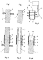
- a pile 1 is brought down into the ground in a manner known per se , e.g., by driving or pressing with the aid of a jack.
- said pile 1 must often be extended by the use of a second pile 2.
- piles driven into the ground e.g., all the way to the hard ground, must be divided into several relatively quite short portions.
- the entire pile formed by such portions will be the object of the same forces which would act on an entire pile.
- special care must be taken with respect to the straightness of the pile entity, so that the pile not would deflect and in the worst case break.
- said pile 1 or a part thereof will be brought by driving or pressing or some other manner into the ground so that the upper end 3 of said pile 1 still will remain over the ground surface 4.
- the driving can also be extended deeper, but then the forming of the extension of the pile 1, i.e. the making of the connection between said pile 1 and said pile 2 in most case will be more difficult.
- a retention ring 5 is arranged around the end 3 of said pile 1, the purpose of this mainly being the function as a retainer for the bushel or sleeve 6 included in the extension as an interconnecting portion and for preventing the movement thereof around the pile 1 to a depth which would render the connection instable.
- said retainer 5 can be used as a gripping point for preventing the pile 1 from sinking deeper by its own weight in such situations where such a ground layer extends at the lower end of the pile which layer does not bear the load caused by the pile's own weight.
- said retainer ring 5 favorably is constituted of two hinged ring portions, which at the side opposite to the hinge (not shown) comprise a clamping locking mechanism known per se (not shown) which appropriately facilitates an opening of the ring and its removal from around the pile also in a lateral direction.
- said heating and attachment of said sleeve 6 can be made in one or two stages, depending on the case.
- said sleeve 6 favorably is arranged in a cold state at the end 3 of the pile 1, suitably by means of an inclination 14 made suitably at the inner surface 7 thereof.
- Upon heating the sleeve 6 will fall down into position around the end 13 of the pile 1 all the way to the retention ring 5. After this the inductive 12 winding is removed and the lower end 13 of the pile 2 constituting the extension is arranged within the free upper end 15 of said sleeve 6.
- the inventive arrangement is especially favorable in connection with such piles 1 which are expressly round in section.
- the arrangement implemented in the manner described is especially suitable for extending tubular or the like piles made of metal and especially of steel.
- the pile tubes 1, 2 as such constitute opposite sleeves.
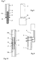
- a generally dowel-like member 17 suitably provided with a retaining flange 16 is arranged into the tubes, correspondingly, which member connects said tubes, as is disclosed in a general manner in Figure 7.
- Said dowel-like member 17 can be pushed into a pile tube 2 either so that the end 13 of said tube is heated in accordance with the above description as evident from Figure 9, in which case also the inner diameter of said tube 2 will grow and facilitate the insertion of a dowel 17a.
- the impact, i.e. the temporary expansion of the mutual clearance caused by the temperature difference can be increased by simultaneously cooling said dowel 17a.
- Figure 8 schematically discloses that an end provided with a dowel-like member 17 in accordance with the above, as disclosed in Figure 7, in itself is cooled in a suitable manner, e.g., by dipping said end into a vessel 18 containing fluid nitrogen.
Landscapes
- Engineering & Computer Science (AREA)
- Structural Engineering (AREA)
- Life Sciences & Earth Sciences (AREA)
- General Life Sciences & Earth Sciences (AREA)
- Mining & Mineral Resources (AREA)
- Paleontology (AREA)
- Civil Engineering (AREA)
- General Engineering & Computer Science (AREA)
- Piles And Underground Anchors (AREA)
- Placing Or Removing Of Piles Or Sheet Piles, Or Accessories Thereof (AREA)
- Forging (AREA)
Abstract
Description
- Figure 1
- in section discloses the end of a pile partially driven into the ground and intended to be extended,
- Figure 2
- in section discloses a pile end according to Figure 1, to which pile end a retention ring has been arranged,
- Figure 3
- in section discloses a sleeve like extension piece and schematically a heating arrangement therefor,
- Figure 4
- in section discloses a pile end to which an extension sleeve has been arranged,
- Figure 5
- in section discloses an extended tube pile still having the retention ring in place,
- Figure 6
- in section discloses an already extended pile which now can be driven deeper down,
- Figure 7
- in section discloses an alternative embodiment which especially can be used in connection with tubular piles, where an interconnecting piece constitutes a pin-like member which extends within the tubular end of the pile,
- Figure 8
- schematically discloses the cooling of a second portion of a pile extension,
- Figure 9
- in section schematically discloses the heating of the end of a pile to be extended, and
- Figure 10
- in section discloses a tube pile portion which has been extended in accordance with the above.
Claims (10)
- An extension arrangement for piles or the like pieces (1, 2) to be driven essentially in a vertical direction, wherein the upper end (3) of a lower pile (1) and the lower end (13) of an extending upper pile (2) to be arranged in an opposed position with respect thereto are interconnected by a separate interconnecting piece (6, 17) which is arranged at said ends (3, 13) of said piles (1, 2) axially with respect to the longitudinal axis of said piles, characterized in that said interconnecting piece (6, 17) is dimensioned to have such a tolerance that at least some lateral surfaces (7, 8) thereof, due to a change in temperature which is established in at least one part (6, 17; 3, 13) of the connection, will radially drift apart from corresponding lateral surfaces (8, 7) at a counterpiece (3, 13; 6, 17) arranged axially in an overlaying position and interconnecting therewith, while said lateral surfaces (7, 8) press against each other, correspondingly, in normal temperature conditions.
- An arrangement as defined in claim 1, characterized in that said interconnecting piece is a metal sleeve (6) to be arranged around the pile, the fit of said sleeve (6) on the end (3, 13) of said pile (1, 2) being such that an expansion which is effected by a heating directed to said sleeve (6) will render possible the introduction of the end (3, 13) of at least one of said piles (1, 2) into the structure (15) constituted by said sleeve (6), but which, on the other hand, in a normal temperature will clamp with its inner surface (7) against the outer surface (8) of said pile (1, 2), the arrangement further comprising means (9) for temporarily heating said sleeve (6) at said pile end (3, 13) in order to achieve said expansion.
- An arrangement as defined in claim 1 or 2, characterized in that said heating means (9) for creating the thermal expansion comprise an inductive transformer (10) and an inductive winding (12), said winding (12) being positionable, for the heating time, temporarily around the part (6, 3, 13) to be expanded.
- An arrangement as defined in any one of claims 1 to 3, characterized in that the arrangement further comprises a retaining ring (5) which favorably temporarily can be arranged around the lower pile end (3).
- An arrangement as defined in any one of claims 1 to 4, characterized in that the lateral surface (7, 8) of said interconnecting piece (6, 17) and/or at least one of said pile ends (3, 13), correspondingly, comprises a grip enhancing coarseness or the like formation, the radial extent of which being smaller than the total radial dimensional change which is due to the change of temperature in said interconnecting piece (6, 17) and/or said pile end (3, 13).
- A method for the extending piles (1, 2) or the like pieces to be driven essentially vertically, in which method for the connection is used outer and inner interconnecting portions (6, 17; 3, 13) to be pushed into an axially mutually overlying disposition, characterized in bringing the inner diameter of said outer interconnecting portion (6; 3, 13) by means of a temperature difference relatively wider than the circumferential dimension of an inner interconnecting portion (3, 13; 17), bringing said outer (6; 3, 13) and said inner (3, 13; 17) interconnecting portion to move, within a mutual relatively loose fit, in the axial direction of the pile (1, 2) into said overlying disposition while the fitting clearance so provided prevails, after which said portions (6, 3, 13; 3, 13, 17) to be interconnected are brought to the normal temperature of the extension in order to remove the fitting clearance brought about by the temporary temperature difference between said portions (6, 3, 13; 3, 13, 17) and for clamping said portions (3, 6, 13, 17) together.
- A method as defined in claim 6, characterized in that a sleeve (6) or the like arranged around the ends (3, 13) of said piles (1, 2) arranged in a mutually opposite disposition is used as said interconnecting portion, wherein said sleeve (6) with respect to its inner extent is brought to be larger than the outer extent of at least one of said pile ends (3, 13), after which said sleeve (6) is brought to shrink around said pile end (3, 13), suitably so that the expansion and, correspondingly, the subsequent shrinking is brought about by bringing said sleeve (6) to constitute the object of a temperature difference.
- A method as defined in claim 7, characterized in that the expansion of said sleeve (6) from a shrinked mode corresponding to a normal temperature to an expanded mode for receiving the end (3, 13) of a pile (1, 2) is brought about by infrared or inductive heating said sleeve suitably to about 300 to 750 °C, favorably about 400 to 650 °C, after which the pile end(s) (3, 13) is/are installed within the extent of said sleeve (6) in an opposite disposition and said sleeve (6) is allowed to cool down to the normal ambient temperature.
- A method as defined in any one of claims 6 to 8, characterized in that said temperature difference is provided both by heating (9) and actively cooling (18) the connection or portions (3, 6, 13, 17) included therein.
- A method as defined in any one of claims 6 to 9, characterized in that the connection is effected in stages so that a separate interconnecting piece (6, 17) and one of said pile ends (3, 13) first are interconnected, after which said interconnecting piece (6, 17) thus connected and the other pile end (13) are connected as a separate operation.
Applications Claiming Priority (2)
| Application Number | Priority Date | Filing Date | Title |
|---|---|---|---|
| FI19992047A FI19992047A7 (en) | 1999-09-23 | 1999-09-23 | Pile joint and method for its implementation |
| FI992047 | 1999-09-23 |
Publications (3)
| Publication Number | Publication Date |
|---|---|
| EP1087062A2 true EP1087062A2 (en) | 2001-03-28 |
| EP1087062A3 EP1087062A3 (en) | 2002-12-04 |
| EP1087062B1 EP1087062B1 (en) | 2008-07-23 |
Family
ID=8555343
Family Applications (1)
| Application Number | Title | Priority Date | Filing Date |
|---|---|---|---|
| EP00120839A Expired - Lifetime EP1087062B1 (en) | 1999-09-23 | 2000-09-25 | Pile joint and a method for implementation thereof |
Country Status (4)
| Country | Link |
|---|---|
| EP (1) | EP1087062B1 (en) |
| AT (1) | ATE402291T1 (en) |
| DE (1) | DE60039563D1 (en) |
| FI (1) | FI19992047A7 (en) |
Cited By (3)
| Publication number | Priority date | Publication date | Assignee | Title |
|---|---|---|---|---|
| NL1029126C2 (en) * | 2005-05-25 | 2006-11-28 | Betonson B V | Pile provided with reinforcement tape. |
| CN103437351A (en) * | 2013-09-18 | 2013-12-11 | 浙江省岩土基础公司 | Treatment method of deviation and fracture remediation of pile body of filling pile |
| CN104314073A (en) * | 2014-09-28 | 2015-01-28 | 嘉兴市晋泉管桩有限公司 | Tubular pile combination external member |
Families Citing this family (1)
| Publication number | Priority date | Publication date | Assignee | Title |
|---|---|---|---|---|
| CN112459052A (en) * | 2020-10-21 | 2021-03-09 | 中国一冶集团有限公司 | Pile extension device for prestressed concrete solid square pile |
Family Cites Families (6)
| Publication number | Priority date | Publication date | Assignee | Title |
|---|---|---|---|---|
| DE1600405A1 (en) * | 1967-05-31 | 1970-02-05 | Becorit Grubenausbau Gmbh | Method and device for the production of pipelines, in particular oil pipes |
| NL7602962A (en) * | 1976-03-22 | 1977-09-26 | Ultra Centrifuge Nederland Nv | Fastening machine for shrink bonding tubular parts - has heated and cooled clamps and operates automatically |
| US4298221A (en) * | 1977-01-26 | 1981-11-03 | Hunting Oilfield Services (U.K.) Limited | Pipe connectors |
| DE2849057A1 (en) * | 1978-11-11 | 1980-05-14 | Karl Heinz Vahlbrauk | Connection between two pipe ends - has sleeve shrunk over abutted pipe ends with reduced dia end portions |
| DE3121602A1 (en) * | 1981-05-30 | 1982-12-23 | Erwaeta Bohrtechnik GmbH, 2300 Kiel | Sleeve connection for the ends of in each case two lengths of pipe |
| JP2000144724A (en) * | 1998-11-16 | 2000-05-26 | Kubota Corp | Connection structure of pile and heating device used for the connection |
-
1999
- 1999-09-23 FI FI19992047A patent/FI19992047A7/en not_active Application Discontinuation
-
2000
- 2000-09-25 EP EP00120839A patent/EP1087062B1/en not_active Expired - Lifetime
- 2000-09-25 DE DE60039563T patent/DE60039563D1/en not_active Expired - Fee Related
- 2000-09-25 AT AT00120839T patent/ATE402291T1/en not_active IP Right Cessation
Cited By (4)
| Publication number | Priority date | Publication date | Assignee | Title |
|---|---|---|---|---|
| NL1029126C2 (en) * | 2005-05-25 | 2006-11-28 | Betonson B V | Pile provided with reinforcement tape. |
| CN103437351A (en) * | 2013-09-18 | 2013-12-11 | 浙江省岩土基础公司 | Treatment method of deviation and fracture remediation of pile body of filling pile |
| CN104314073A (en) * | 2014-09-28 | 2015-01-28 | 嘉兴市晋泉管桩有限公司 | Tubular pile combination external member |
| CN104314073B (en) * | 2014-09-28 | 2016-02-03 | 嘉兴市晋泉管桩有限公司 | A kind of pile tube combination set |
Also Published As
| Publication number | Publication date |
|---|---|
| ATE402291T1 (en) | 2008-08-15 |
| FI19992047A7 (en) | 2001-03-24 |
| DE60039563D1 (en) | 2008-09-04 |
| FI19992047L (en) | 2001-03-23 |
| EP1087062B1 (en) | 2008-07-23 |
| EP1087062A3 (en) | 2002-12-04 |
Similar Documents
| Publication | Publication Date | Title |
|---|---|---|
| US5729952A (en) | Mechanical rebar couplers | |
| US4009550A (en) | Modular piling system | |
| US4053247A (en) | Double sleeve pipe coupler | |
| EP1087062B1 (en) | Pile joint and a method for implementation thereof | |
| US20240410169A1 (en) | Rebar system for use with concrete reinforcing bars | |
| WO1993018253A1 (en) | Mast base | |
| JPH07292662A (en) | Steel pipe pile connection structure | |
| US20230332366A1 (en) | Self-locking joint for reinforced concrete pile sections | |
| EP0554972A1 (en) | Reinforcing bar coupling | |
| JPH0525966B2 (en) | ||
| WO2003087492A1 (en) | Reinforcing bar coupler | |
| NO310088B1 (en) | Device for joining two elements | |
| KR100421198B1 (en) | construction method of socket type steel pipe for connecting thereof | |
| WO2016171566A1 (en) | Concrete pile connector | |
| KR102703323B1 (en) | Connecting device for lifting phc pile apparatus | |
| KR102931735B1 (en) | Joint device of PHC Pile | |
| JP4101077B2 (en) | Core joint structure | |
| KR102684324B1 (en) | an auxilary pile for constructing PHC pile | |
| KR102613525B1 (en) | Pile pressing system with improved base reinforcement and resistance to buckling | |
| JP7288199B2 (en) | METHOD FOR MANUFACTURING STEEL PIPE PILE WITH INTERNAL PROJECTS, CONSTRUCTION METHOD OF STEEL PIPE PILE, AND STEEL PIPE PILE WITH INNER PROJECTIONS | |
| FI81415B (en) | Connecting piece for driven post | |
| JP2526356Y2 (en) | Pile connection device | |
| CN213233425U (en) | Connecting piece for precast pile with bottom barrel | |
| JP2000290997A (en) | Pile | |
| JP3311964B2 (en) | Joint of foundation pile |
Legal Events
| Date | Code | Title | Description |
|---|---|---|---|
| PUAI | Public reference made under article 153(3) epc to a published international application that has entered the european phase |
Free format text: ORIGINAL CODE: 0009012 |
|
| AK | Designated contracting states |
Kind code of ref document: A2 Designated state(s): AT BE CH CY DE DK ES FI FR GB GR IE IT LI LU MC NL PT SE |
|
| AX | Request for extension of the european patent |
Free format text: AL;LT;LV;MK;RO;SI |
|
| PUAL | Search report despatched |
Free format text: ORIGINAL CODE: 0009013 |
|
| AK | Designated contracting states |
Kind code of ref document: A3 Designated state(s): AT BE CH CY DE DK ES FI FR GB GR IE IT LI LU MC NL PT SE |
|
| AX | Request for extension of the european patent |
Free format text: AL;LT;LV;MK;RO;SI |
|
| 17P | Request for examination filed |
Effective date: 20030603 |
|
| AKX | Designation fees paid |
Designated state(s): AT BE CH CY DE DK ES FI FR GB GR IE IT LI LU MC NL PT SE |
|
| 17Q | First examination report despatched |
Effective date: 20040305 |
|
| GRAP | Despatch of communication of intention to grant a patent |
Free format text: ORIGINAL CODE: EPIDOSNIGR1 |
|
| GRAS | Grant fee paid |
Free format text: ORIGINAL CODE: EPIDOSNIGR3 |
|
| GRAA | (expected) grant |
Free format text: ORIGINAL CODE: 0009210 |
|
| AK | Designated contracting states |
Kind code of ref document: B1 Designated state(s): AT BE CH CY DE DK ES FI FR GB GR IE IT LI LU MC NL PT SE |
|
| REG | Reference to a national code |
Ref country code: GB Ref legal event code: FG4D |
|
| REG | Reference to a national code |
Ref country code: CH Ref legal event code: EP |
|
| REG | Reference to a national code |
Ref country code: IE Ref legal event code: FG4D |
|
| REF | Corresponds to: |
Ref document number: 60039563 Country of ref document: DE Date of ref document: 20080904 Kind code of ref document: P |
|
| REG | Reference to a national code |
Ref country code: SE Ref legal event code: TRGR |
|
| PG25 | Lapsed in a contracting state [announced via postgrant information from national office to epo] |
Ref country code: PT Free format text: LAPSE BECAUSE OF FAILURE TO SUBMIT A TRANSLATION OF THE DESCRIPTION OR TO PAY THE FEE WITHIN THE PRESCRIBED TIME-LIMIT Effective date: 20081223 Ref country code: ES Free format text: LAPSE BECAUSE OF FAILURE TO SUBMIT A TRANSLATION OF THE DESCRIPTION OR TO PAY THE FEE WITHIN THE PRESCRIBED TIME-LIMIT Effective date: 20081103 |
|
| PG25 | Lapsed in a contracting state [announced via postgrant information from national office to epo] |
Ref country code: AT Free format text: LAPSE BECAUSE OF FAILURE TO SUBMIT A TRANSLATION OF THE DESCRIPTION OR TO PAY THE FEE WITHIN THE PRESCRIBED TIME-LIMIT Effective date: 20080723 |
|
| PG25 | Lapsed in a contracting state [announced via postgrant information from national office to epo] |
Ref country code: BE Free format text: LAPSE BECAUSE OF FAILURE TO SUBMIT A TRANSLATION OF THE DESCRIPTION OR TO PAY THE FEE WITHIN THE PRESCRIBED TIME-LIMIT Effective date: 20080723 |
|
| PG25 | Lapsed in a contracting state [announced via postgrant information from national office to epo] |
Ref country code: MC Free format text: LAPSE BECAUSE OF NON-PAYMENT OF DUE FEES Effective date: 20080930 Ref country code: DK Free format text: LAPSE BECAUSE OF FAILURE TO SUBMIT A TRANSLATION OF THE DESCRIPTION OR TO PAY THE FEE WITHIN THE PRESCRIBED TIME-LIMIT Effective date: 20080723 |
|
| REG | Reference to a national code |
Ref country code: CH Ref legal event code: PL |
|
| PLBE | No opposition filed within time limit |
Free format text: ORIGINAL CODE: 0009261 |
|
| STAA | Information on the status of an ep patent application or granted ep patent |
Free format text: STATUS: NO OPPOSITION FILED WITHIN TIME LIMIT |
|
| GBPC | Gb: european patent ceased through non-payment of renewal fee |
Effective date: 20081023 |
|
| REG | Reference to a national code |
Ref country code: IE Ref legal event code: MM4A |
|
| 26N | No opposition filed |
Effective date: 20090424 |
|
| REG | Reference to a national code |
Ref country code: FR Ref legal event code: ST Effective date: 20090529 |
|
| PG25 | Lapsed in a contracting state [announced via postgrant information from national office to epo] |
Ref country code: IE Free format text: LAPSE BECAUSE OF NON-PAYMENT OF DUE FEES Effective date: 20080925 |
|
| PG25 | Lapsed in a contracting state [announced via postgrant information from national office to epo] |
Ref country code: IT Free format text: LAPSE BECAUSE OF FAILURE TO SUBMIT A TRANSLATION OF THE DESCRIPTION OR TO PAY THE FEE WITHIN THE PRESCRIBED TIME-LIMIT Effective date: 20080723 Ref country code: DE Free format text: LAPSE BECAUSE OF NON-PAYMENT OF DUE FEES Effective date: 20090401 |
|
| PG25 | Lapsed in a contracting state [announced via postgrant information from national office to epo] |
Ref country code: LI Free format text: LAPSE BECAUSE OF NON-PAYMENT OF DUE FEES Effective date: 20080930 Ref country code: CH Free format text: LAPSE BECAUSE OF NON-PAYMENT OF DUE FEES Effective date: 20080930 Ref country code: FR Free format text: LAPSE BECAUSE OF NON-PAYMENT OF DUE FEES Effective date: 20080930 |
|
| PG25 | Lapsed in a contracting state [announced via postgrant information from national office to epo] |
Ref country code: GB Free format text: LAPSE BECAUSE OF NON-PAYMENT OF DUE FEES Effective date: 20081023 |
|
| PG25 | Lapsed in a contracting state [announced via postgrant information from national office to epo] |
Ref country code: LU Free format text: LAPSE BECAUSE OF NON-PAYMENT OF DUE FEES Effective date: 20080925 |
|
| PG25 | Lapsed in a contracting state [announced via postgrant information from national office to epo] |
Ref country code: CY Free format text: LAPSE BECAUSE OF FAILURE TO SUBMIT A TRANSLATION OF THE DESCRIPTION OR TO PAY THE FEE WITHIN THE PRESCRIBED TIME-LIMIT Effective date: 20080723 |
|
| PG25 | Lapsed in a contracting state [announced via postgrant information from national office to epo] |
Ref country code: GR Free format text: LAPSE BECAUSE OF FAILURE TO SUBMIT A TRANSLATION OF THE DESCRIPTION OR TO PAY THE FEE WITHIN THE PRESCRIBED TIME-LIMIT Effective date: 20081024 |
|
| PGFP | Annual fee paid to national office [announced via postgrant information from national office to epo] |
Ref country code: FI Payment date: 20110920 Year of fee payment: 12 Ref country code: SE Payment date: 20110920 Year of fee payment: 12 |
|
| PGFP | Annual fee paid to national office [announced via postgrant information from national office to epo] |
Ref country code: NL Payment date: 20111005 Year of fee payment: 12 |
|
| REG | Reference to a national code |
Ref country code: NL Ref legal event code: V1 Effective date: 20130401 |
|
| PG25 | Lapsed in a contracting state [announced via postgrant information from national office to epo] |
Ref country code: FI Free format text: LAPSE BECAUSE OF NON-PAYMENT OF DUE FEES Effective date: 20120925 Ref country code: SE Free format text: LAPSE BECAUSE OF NON-PAYMENT OF DUE FEES Effective date: 20120926 |
|
| REG | Reference to a national code |
Ref country code: SE Ref legal event code: EUG |
|
| PG25 | Lapsed in a contracting state [announced via postgrant information from national office to epo] |
Ref country code: NL Free format text: LAPSE BECAUSE OF NON-PAYMENT OF DUE FEES Effective date: 20130401 |