EP1086804A2 - Silicone bag assembly manufacturing apparatus - Google Patents
Silicone bag assembly manufacturing apparatus Download PDFInfo
- Publication number
- EP1086804A2 EP1086804A2 EP00118653A EP00118653A EP1086804A2 EP 1086804 A2 EP1086804 A2 EP 1086804A2 EP 00118653 A EP00118653 A EP 00118653A EP 00118653 A EP00118653 A EP 00118653A EP 1086804 A2 EP1086804 A2 EP 1086804A2
- Authority
- EP
- European Patent Office
- Prior art keywords
- membrane
- station
- endless belt
- belt system
- tube
- Prior art date
- Legal status (The legal status is an assumption and is not a legal conclusion. Google has not performed a legal analysis and makes no representation as to the accuracy of the status listed.)
- Withdrawn
Links
Images



Classifications
-
- A—HUMAN NECESSITIES
- A61—MEDICAL OR VETERINARY SCIENCE; HYGIENE
- A61J—CONTAINERS SPECIALLY ADAPTED FOR MEDICAL OR PHARMACEUTICAL PURPOSES; DEVICES OR METHODS SPECIALLY ADAPTED FOR BRINGING PHARMACEUTICAL PRODUCTS INTO PARTICULAR PHYSICAL OR ADMINISTERING FORMS; DEVICES FOR ADMINISTERING FOOD OR MEDICINES ORALLY; BABY COMFORTERS; DEVICES FOR RECEIVING SPITTLE
- A61J1/00—Containers specially adapted for medical or pharmaceutical purposes
- A61J1/05—Containers specially adapted for medical or pharmaceutical purposes for collecting, storing or administering blood, plasma or medical fluids ; Infusion or perfusion containers
- A61J1/10—Bag-type containers
-
- B—PERFORMING OPERATIONS; TRANSPORTING
- B29—WORKING OF PLASTICS; WORKING OF SUBSTANCES IN A PLASTIC STATE IN GENERAL
- B29C—SHAPING OR JOINING OF PLASTICS; SHAPING OF MATERIAL IN A PLASTIC STATE, NOT OTHERWISE PROVIDED FOR; AFTER-TREATMENT OF THE SHAPED PRODUCTS, e.g. REPAIRING
- B29C65/00—Joining or sealing of preformed parts, e.g. welding of plastics materials; Apparatus therefor
- B29C65/02—Joining or sealing of preformed parts, e.g. welding of plastics materials; Apparatus therefor by heating, with or without pressure
- B29C65/18—Joining or sealing of preformed parts, e.g. welding of plastics materials; Apparatus therefor by heating, with or without pressure using heated tools
-
- B—PERFORMING OPERATIONS; TRANSPORTING
- B29—WORKING OF PLASTICS; WORKING OF SUBSTANCES IN A PLASTIC STATE IN GENERAL
- B29C—SHAPING OR JOINING OF PLASTICS; SHAPING OF MATERIAL IN A PLASTIC STATE, NOT OTHERWISE PROVIDED FOR; AFTER-TREATMENT OF THE SHAPED PRODUCTS, e.g. REPAIRING
- B29C65/00—Joining or sealing of preformed parts, e.g. welding of plastics materials; Apparatus therefor
- B29C65/48—Joining or sealing of preformed parts, e.g. welding of plastics materials; Apparatus therefor using adhesives, i.e. using supplementary joining material; solvent bonding
- B29C65/52—Joining or sealing of preformed parts, e.g. welding of plastics materials; Apparatus therefor using adhesives, i.e. using supplementary joining material; solvent bonding characterised by the way of applying the adhesive
- B29C65/524—Joining or sealing of preformed parts, e.g. welding of plastics materials; Apparatus therefor using adhesives, i.e. using supplementary joining material; solvent bonding characterised by the way of applying the adhesive by applying the adhesive from an outlet device in contact with, or almost in contact with, the surface of the part to be joined
-
- B—PERFORMING OPERATIONS; TRANSPORTING
- B29—WORKING OF PLASTICS; WORKING OF SUBSTANCES IN A PLASTIC STATE IN GENERAL
- B29C—SHAPING OR JOINING OF PLASTICS; SHAPING OF MATERIAL IN A PLASTIC STATE, NOT OTHERWISE PROVIDED FOR; AFTER-TREATMENT OF THE SHAPED PRODUCTS, e.g. REPAIRING
- B29C66/00—General aspects of processes or apparatus for joining preformed parts
- B29C66/01—General aspects dealing with the joint area or with the area to be joined
- B29C66/05—Particular design of joint configurations
- B29C66/10—Particular design of joint configurations particular design of the joint cross-sections
- B29C66/11—Joint cross-sections comprising a single joint-segment, i.e. one of the parts to be joined comprising a single joint-segment in the joint cross-section
- B29C66/112—Single lapped joints
- B29C66/1122—Single lap to lap joints, i.e. overlap joints
-
- B—PERFORMING OPERATIONS; TRANSPORTING
- B29—WORKING OF PLASTICS; WORKING OF SUBSTANCES IN A PLASTIC STATE IN GENERAL
- B29C—SHAPING OR JOINING OF PLASTICS; SHAPING OF MATERIAL IN A PLASTIC STATE, NOT OTHERWISE PROVIDED FOR; AFTER-TREATMENT OF THE SHAPED PRODUCTS, e.g. REPAIRING
- B29C66/00—General aspects of processes or apparatus for joining preformed parts
- B29C66/01—General aspects dealing with the joint area or with the area to be joined
- B29C66/05—Particular design of joint configurations
- B29C66/10—Particular design of joint configurations particular design of the joint cross-sections
- B29C66/13—Single flanged joints; Fin-type joints; Single hem joints; Edge joints; Interpenetrating fingered joints; Other specific particular designs of joint cross-sections not provided for in groups B29C66/11 - B29C66/12
- B29C66/133—Fin-type joints, the parts to be joined being flexible
-
- B—PERFORMING OPERATIONS; TRANSPORTING
- B29—WORKING OF PLASTICS; WORKING OF SUBSTANCES IN A PLASTIC STATE IN GENERAL
- B29C—SHAPING OR JOINING OF PLASTICS; SHAPING OF MATERIAL IN A PLASTIC STATE, NOT OTHERWISE PROVIDED FOR; AFTER-TREATMENT OF THE SHAPED PRODUCTS, e.g. REPAIRING
- B29C66/00—General aspects of processes or apparatus for joining preformed parts
- B29C66/01—General aspects dealing with the joint area or with the area to be joined
- B29C66/05—Particular design of joint configurations
- B29C66/20—Particular design of joint configurations particular design of the joint lines, e.g. of the weld lines
- B29C66/24—Particular design of joint configurations particular design of the joint lines, e.g. of the weld lines said joint lines being closed or non-straight
- B29C66/242—Particular design of joint configurations particular design of the joint lines, e.g. of the weld lines said joint lines being closed or non-straight said joint lines being closed, i.e. forming closed contours
- B29C66/2422—Particular design of joint configurations particular design of the joint lines, e.g. of the weld lines said joint lines being closed or non-straight said joint lines being closed, i.e. forming closed contours being circular, oval or elliptical
- B29C66/24221—Particular design of joint configurations particular design of the joint lines, e.g. of the weld lines said joint lines being closed or non-straight said joint lines being closed, i.e. forming closed contours being circular, oval or elliptical being circular
-
- B—PERFORMING OPERATIONS; TRANSPORTING
- B29—WORKING OF PLASTICS; WORKING OF SUBSTANCES IN A PLASTIC STATE IN GENERAL
- B29C—SHAPING OR JOINING OF PLASTICS; SHAPING OF MATERIAL IN A PLASTIC STATE, NOT OTHERWISE PROVIDED FOR; AFTER-TREATMENT OF THE SHAPED PRODUCTS, e.g. REPAIRING
- B29C66/00—General aspects of processes or apparatus for joining preformed parts
- B29C66/40—General aspects of joining substantially flat articles, e.g. plates, sheets or web-like materials; Making flat seams in tubular or hollow articles; Joining single elements to substantially flat surfaces
- B29C66/41—Joining substantially flat articles ; Making flat seams in tubular or hollow articles
- B29C66/43—Joining a relatively small portion of the surface of said articles
- B29C66/431—Joining the articles to themselves
- B29C66/4312—Joining the articles to themselves for making flat seams in tubular or hollow articles, e.g. transversal seams
- B29C66/43121—Closing the ends of tubular or hollow single articles, e.g. closing the ends of bags
-
- B—PERFORMING OPERATIONS; TRANSPORTING
- B29—WORKING OF PLASTICS; WORKING OF SUBSTANCES IN A PLASTIC STATE IN GENERAL
- B29C—SHAPING OR JOINING OF PLASTICS; SHAPING OF MATERIAL IN A PLASTIC STATE, NOT OTHERWISE PROVIDED FOR; AFTER-TREATMENT OF THE SHAPED PRODUCTS, e.g. REPAIRING
- B29C66/00—General aspects of processes or apparatus for joining preformed parts
- B29C66/50—General aspects of joining tubular articles; General aspects of joining long products, i.e. bars or profiled elements; General aspects of joining single elements to tubular articles, hollow articles or bars; General aspects of joining several hollow-preforms to form hollow or tubular articles
- B29C66/51—Joining tubular articles, profiled elements or bars; Joining single elements to tubular articles, hollow articles or bars; Joining several hollow-preforms to form hollow or tubular articles
- B29C66/53—Joining single elements to tubular articles, hollow articles or bars
- B29C66/532—Joining single elements to the wall of tubular articles, hollow articles or bars
- B29C66/5326—Joining single elements to the wall of tubular articles, hollow articles or bars said single elements being substantially flat
- B29C66/53261—Enclosing tubular articles between substantially flat elements
- B29C66/53262—Enclosing spouts between the walls of bags, e.g. of medical bags
-
- B—PERFORMING OPERATIONS; TRANSPORTING
- B29—WORKING OF PLASTICS; WORKING OF SUBSTANCES IN A PLASTIC STATE IN GENERAL
- B29C—SHAPING OR JOINING OF PLASTICS; SHAPING OF MATERIAL IN A PLASTIC STATE, NOT OTHERWISE PROVIDED FOR; AFTER-TREATMENT OF THE SHAPED PRODUCTS, e.g. REPAIRING
- B29C66/00—General aspects of processes or apparatus for joining preformed parts
- B29C66/70—General aspects of processes or apparatus for joining preformed parts characterised by the composition, physical properties or the structure of the material of the parts to be joined; Joining with non-plastics material
- B29C66/71—General aspects of processes or apparatus for joining preformed parts characterised by the composition, physical properties or the structure of the material of the parts to be joined; Joining with non-plastics material characterised by the composition of the plastics material of the parts to be joined
-
- B—PERFORMING OPERATIONS; TRANSPORTING
- B29—WORKING OF PLASTICS; WORKING OF SUBSTANCES IN A PLASTIC STATE IN GENERAL
- B29C—SHAPING OR JOINING OF PLASTICS; SHAPING OF MATERIAL IN A PLASTIC STATE, NOT OTHERWISE PROVIDED FOR; AFTER-TREATMENT OF THE SHAPED PRODUCTS, e.g. REPAIRING
- B29C66/00—General aspects of processes or apparatus for joining preformed parts
- B29C66/80—General aspects of machine operations or constructions and parts thereof
- B29C66/81—General aspects of the pressing elements, i.e. the elements applying pressure on the parts to be joined in the area to be joined, e.g. the welding jaws or clamps
- B29C66/816—General aspects of the pressing elements, i.e. the elements applying pressure on the parts to be joined in the area to be joined, e.g. the welding jaws or clamps characterised by the mounting of the pressing elements, e.g. of the welding jaws or clamps
- B29C66/8161—General aspects of the pressing elements, i.e. the elements applying pressure on the parts to be joined in the area to be joined, e.g. the welding jaws or clamps characterised by the mounting of the pressing elements, e.g. of the welding jaws or clamps said pressing elements being supported or backed-up by springs or by resilient material
-
- B—PERFORMING OPERATIONS; TRANSPORTING
- B29—WORKING OF PLASTICS; WORKING OF SUBSTANCES IN A PLASTIC STATE IN GENERAL
- B29C—SHAPING OR JOINING OF PLASTICS; SHAPING OF MATERIAL IN A PLASTIC STATE, NOT OTHERWISE PROVIDED FOR; AFTER-TREATMENT OF THE SHAPED PRODUCTS, e.g. REPAIRING
- B29C66/00—General aspects of processes or apparatus for joining preformed parts
- B29C66/80—General aspects of machine operations or constructions and parts thereof
- B29C66/83—General aspects of machine operations or constructions and parts thereof characterised by the movement of the joining or pressing tools
- B29C66/834—General aspects of machine operations or constructions and parts thereof characterised by the movement of the joining or pressing tools moving with the parts to be joined
- B29C66/8351—Jaws mounted on rollers, cylinders, drums, bands, belts or chains; Flying jaws
- B29C66/83521—Jaws mounted on rollers, cylinders, drums, bands, belts or chains; Flying jaws jaws mounted on bands or belts
- B29C66/83523—Cooperating jaws mounted on cooperating bands or belts and moving in a closed path
-
- B—PERFORMING OPERATIONS; TRANSPORTING
- B29—WORKING OF PLASTICS; WORKING OF SUBSTANCES IN A PLASTIC STATE IN GENERAL
- B29C—SHAPING OR JOINING OF PLASTICS; SHAPING OF MATERIAL IN A PLASTIC STATE, NOT OTHERWISE PROVIDED FOR; AFTER-TREATMENT OF THE SHAPED PRODUCTS, e.g. REPAIRING
- B29C66/00—General aspects of processes or apparatus for joining preformed parts
- B29C66/80—General aspects of machine operations or constructions and parts thereof
- B29C66/84—Specific machine types or machines suitable for specific applications
- B29C66/843—Machines for making separate joints at the same time in different planes; Machines for making separate joints at the same time mounted in parallel or in series
- B29C66/8432—Machines for making separate joints at the same time mounted in parallel or in series
-
- A—HUMAN NECESSITIES
- A61—MEDICAL OR VETERINARY SCIENCE; HYGIENE
- A61J—CONTAINERS SPECIALLY ADAPTED FOR MEDICAL OR PHARMACEUTICAL PURPOSES; DEVICES OR METHODS SPECIALLY ADAPTED FOR BRINGING PHARMACEUTICAL PRODUCTS INTO PARTICULAR PHYSICAL OR ADMINISTERING FORMS; DEVICES FOR ADMINISTERING FOOD OR MEDICINES ORALLY; BABY COMFORTERS; DEVICES FOR RECEIVING SPITTLE
- A61J1/00—Containers specially adapted for medical or pharmaceutical purposes
- A61J1/14—Details; Accessories therefor
- A61J1/1475—Inlet or outlet ports
-
- B—PERFORMING OPERATIONS; TRANSPORTING
- B29—WORKING OF PLASTICS; WORKING OF SUBSTANCES IN A PLASTIC STATE IN GENERAL
- B29C—SHAPING OR JOINING OF PLASTICS; SHAPING OF MATERIAL IN A PLASTIC STATE, NOT OTHERWISE PROVIDED FOR; AFTER-TREATMENT OF THE SHAPED PRODUCTS, e.g. REPAIRING
- B29C65/00—Joining or sealing of preformed parts, e.g. welding of plastics materials; Apparatus therefor
- B29C65/02—Joining or sealing of preformed parts, e.g. welding of plastics materials; Apparatus therefor by heating, with or without pressure
- B29C65/18—Joining or sealing of preformed parts, e.g. welding of plastics materials; Apparatus therefor by heating, with or without pressure using heated tools
- B29C65/24—Joining or sealing of preformed parts, e.g. welding of plastics materials; Apparatus therefor by heating, with or without pressure using heated tools characterised by the means for heating the tool
- B29C65/30—Electrical means
- B29C65/305—Electrical means involving the use of cartridge heaters
-
- B—PERFORMING OPERATIONS; TRANSPORTING
- B29—WORKING OF PLASTICS; WORKING OF SUBSTANCES IN A PLASTIC STATE IN GENERAL
- B29C—SHAPING OR JOINING OF PLASTICS; SHAPING OF MATERIAL IN A PLASTIC STATE, NOT OTHERWISE PROVIDED FOR; AFTER-TREATMENT OF THE SHAPED PRODUCTS, e.g. REPAIRING
- B29C65/00—Joining or sealing of preformed parts, e.g. welding of plastics materials; Apparatus therefor
- B29C65/48—Joining or sealing of preformed parts, e.g. welding of plastics materials; Apparatus therefor using adhesives, i.e. using supplementary joining material; solvent bonding
- B29C65/4805—Joining or sealing of preformed parts, e.g. welding of plastics materials; Apparatus therefor using adhesives, i.e. using supplementary joining material; solvent bonding characterised by the type of adhesives
- B29C65/483—Reactive adhesives, e.g. chemically curing adhesives
- B29C65/4835—Heat curing adhesives
-
- B—PERFORMING OPERATIONS; TRANSPORTING
- B29—WORKING OF PLASTICS; WORKING OF SUBSTANCES IN A PLASTIC STATE IN GENERAL
- B29C—SHAPING OR JOINING OF PLASTICS; SHAPING OF MATERIAL IN A PLASTIC STATE, NOT OTHERWISE PROVIDED FOR; AFTER-TREATMENT OF THE SHAPED PRODUCTS, e.g. REPAIRING
- B29C65/00—Joining or sealing of preformed parts, e.g. welding of plastics materials; Apparatus therefor
- B29C65/48—Joining or sealing of preformed parts, e.g. welding of plastics materials; Apparatus therefor using adhesives, i.e. using supplementary joining material; solvent bonding
- B29C65/52—Joining or sealing of preformed parts, e.g. welding of plastics materials; Apparatus therefor using adhesives, i.e. using supplementary joining material; solvent bonding characterised by the way of applying the adhesive
- B29C65/54—Joining or sealing of preformed parts, e.g. welding of plastics materials; Apparatus therefor using adhesives, i.e. using supplementary joining material; solvent bonding characterised by the way of applying the adhesive between pre-assembled parts
-
- B—PERFORMING OPERATIONS; TRANSPORTING
- B29—WORKING OF PLASTICS; WORKING OF SUBSTANCES IN A PLASTIC STATE IN GENERAL
- B29L—INDEXING SCHEME ASSOCIATED WITH SUBCLASS B29C, RELATING TO PARTICULAR ARTICLES
- B29L2031/00—Other particular articles
- B29L2031/712—Containers; Packaging elements or accessories, Packages
- B29L2031/7148—Blood bags, medical bags
-
- B—PERFORMING OPERATIONS; TRANSPORTING
- B31—MAKING ARTICLES OF PAPER, CARDBOARD OR MATERIAL WORKED IN A MANNER ANALOGOUS TO PAPER; WORKING PAPER, CARDBOARD OR MATERIAL WORKED IN A MANNER ANALOGOUS TO PAPER
- B31B—MAKING CONTAINERS OF PAPER, CARDBOARD OR MATERIAL WORKED IN A MANNER ANALOGOUS TO PAPER
- B31B70/00—Making flexible containers, e.g. envelopes or bags
- B31B70/74—Auxiliary operations
- B31B70/81—Forming or attaching accessories, e.g. opening devices, closures or tear strings
- B31B70/84—Forming or attaching means for filling or dispensing contents, e.g. valves or spouts
- B31B70/844—Applying rigid valves, spouts, or filling tubes
Definitions
- the adhesive injection station 88 Downstream from the tube insertion station is an adhesive injection station 88.
- the adhesive injection station 88 is arranged to inject liquid adhesive into the open end of the membrane 80 after a first clamp block 70 engages the membrane 80 but before the second clamp block 72 engages the membrane 80.
- Exemplary adhesive is Sani-Tech®45 or 70 LIM silicone adhesive, manufactured by Norton Performance Plastics Corporation of Sparta, New Jersey.
- the adhesive injection station 88 includes an injection head which illustratively is of the form shown in Figure 10 and designated generally by the reference numeral 92.
- the head 92 is bifurcated with a gap 94 for receiving a tube 86.
- the injection station 88 is arranged to cause the head 92 to move along the closed path shown in Figure 11.
- the head 92 is caused to move downwardly as shown by the arrow 98 and then inwardly to extend into an open end of a membrane 80, as shown by the arrow 100, with the tube 86 being received within the gap 94.
- the head 92 moves laterally as indicated by the arrow 102, following the movement of the membrane 80.
- liquid adhesive is injected into the open end of the membrane 80 through the slots 104 of the head 92.
- the clamp block 70 prevents the adhesive from reaching the interior of the tubular membrane 80.
- the assembly 20 can be constructed to have any desired capacity. As presently contemplated, the capacity will probably be in the range from about 750 ml up to about 5 liters, but larger capacity assemblies, even up to one thousand liters, are within the scope of this invention. Further, the assembly 20 is not limited to any specific use, although it is presently contemplated that it will be used for storage (and cryogenic shipment) of intermediate or concentrated drug products during manufacture in an industrial setting.
- inventive apparatus results in a number of manufacturing advantages.
- stock items of tubing and tubular membranes can be utilized.
- the clamp design leaves the diameter of the tubing intact while insuring a good seal between the tubing and the membrane. Additionally, an all silicone (including adhesive) product is produced.
Landscapes
- Engineering & Computer Science (AREA)
- Mechanical Engineering (AREA)
- Health & Medical Sciences (AREA)
- Animal Behavior & Ethology (AREA)
- Pharmacology & Pharmacy (AREA)
- Life Sciences & Earth Sciences (AREA)
- Hematology (AREA)
- General Health & Medical Sciences (AREA)
- Public Health (AREA)
- Veterinary Medicine (AREA)
- Medical Preparation Storing Or Oral Administration Devices (AREA)
- Casting Or Compression Moulding Of Plastics Or The Like (AREA)
- Making Paper Articles (AREA)
- External Artificial Organs (AREA)
- Lining Or Joining Of Plastics Or The Like (AREA)
Abstract
Description
Claims (7)
- Apparatus for forming a bag assembly from a tube and a tubular flexible membrane with opposed open ends, comprising:a base adapted to support said membrane and said tube with said tube extending into one of said open ends of said membrane;a first clamp adapted to flatten and clamp said membrane to itself and to said tube along a first line spaced from and substantially parallel to said one open end;a first injector adapted to inject liquid adhesive into said one open end and around said tube between said one open end and said first line; anda second clamp adapted to flatten and clamp said membrane to itself and to said tube between said first line and said one open end.
- The apparatus according to Claim 1 wherein said bag assembly includes a second tube and the base is adapted to support said membrane with said second tube extending into the other open end of said membrane, the apparatus further comprising:a third clamp adapted to flatten and clamp said membrane to itself along a second line spaced from and substantially parallel to said other open end;a second injector adapted to inject liquid adhesive into said other open end and around said second tube between said other open end and said second line; anda fourth clamp adapted to flatten and clamp said membrane to itself and to said second tube between said second line and said other open end.
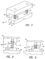
- Continuous production manufacturing apparatus for forming a plurality of bag assemblies each from a respective tubular flexible membrane with opposed open ends and a respective tube, the apparatus comprising:a first endless belt system arranged for movement in a first angular direction;a second endless belt system arranged for movement in a second angular direction opposite said first angular direction, wherein said second endless belt system overlies a first portion of said first endless belt system so as to leave exposed a second portion of said first endless belt system which immediately precedes said first portion in the direction of travel of said first endless belt system;a plurality of first stations mounted to said first endless belt system at a plurality of equally spaced locations and each comprising:a base adapted to support a respective membrane with a respective tube extending into one of the open ends of the respective membrane;a plurality of second stations mounted to said second endless belt system at a plurality of equally spaced locations, wherein the spacing between adjacent ones of said second stations is equal to the spacing between adjacent ones of said first stations, each of said second stations comprising:a first clamp member spring coupled to said second endless belt system so as to be yieldably biased away from said second endless belt system, said first clamp member contacting a respective base when the respective second station overlies a respective first station in said first portion of said first endless belt system; anda second clamp member secured to said second endless belt system and contacting the respective underlying first station base when the respective second station overlies said underlying first station within said first portion of said first endless belt system;
wherein the first clamp member contacts the respective base inward of where the second contact member contacts the respective base, and wherein the first clamp member is arranged to contact the respective base prior to the second clamp member contacting the respective base;a membrane placement station adjacent said second portion of said first endless belt system and arranged to place a respective flexible membrane on each first station base as it passes said membrane placement station;a tube insertion station adjacent said second portion of said first endless belt system and arranged to insert a respective tube into an open end of each flexible membrane as it passes said tube placement station while on its respective first station base; andan adhesive injection station adjacent said first portion of said first endless belt system and arranged to inject liquid adhesive into the open end of each flexible membrane as it passes said adhesive injection station while on its respective first station base with a respective tube inserted therein and a respective first clamp member contacting the membrane but before a respective second clamp member contacts the membrane. - The apparatus according to Claim 3 wherein:the membrane placement station includes an elongated tubular membrane wound on a spool; andthe membrane placement station is arranged to cut a predetermined length of membrane from the elongated tubular membrane.
- The apparatus according to Claim 3 wherein:the adhesive injection station includes a bifurcated injection head; andthe adhesive injection station is arranged to move said injection head from an initial location along a closed path having the following path segments:a) downwardly so that a tube is received in the bifurcation;b) inwardly to insert the injection head into an open end of a flexible membrane disposed on a base;c) laterally to travel with the flexible membrane while adhesive is injected;d) outwardly to remove the injection head from the flexible membrane open end;e) upwardly; andf) laterally in the direction opposite to movement of the flexible membrane and back to the initial location.
- The apparatus according to Claim 3 wherein each of said plurality of first stations and each of said plurality of second stations includes a heating element.
- The apparatus according to Claim 3 wherein:said second clamp member comprises a second block secured to said second endless belt system, said second block being generally rectilinear with an L-shaped cross-section when viewed orthogonally to the direction of travel of said second block, and with the opening of the L-shape being directed outwardly and away from the second endless belt system; andsaid first clamp member comprises a first block which is generally rectilinear and sized to fit within the opening of the second block, the first block being spring coupled to the second block and yieldably biased out of the opening in a direction away from the second endless belt system;
whereby, as a second station approaches a first station, the first block of that second station contacts the base of that first station and is then moved into the opening of the second block of that second station until that second block contacts that base.
Applications Claiming Priority (2)
| Application Number | Priority Date | Filing Date | Title |
|---|---|---|---|
| US09/406,584 US6632164B1 (en) | 1999-09-27 | 1999-09-27 | Silicone bag assembly manufacturing apparatus |
| US406584 | 1999-09-27 |
Publications (2)
| Publication Number | Publication Date |
|---|---|
| EP1086804A2 true EP1086804A2 (en) | 2001-03-28 |
| EP1086804A3 EP1086804A3 (en) | 2001-10-10 |
Family
ID=23608630
Family Applications (1)
| Application Number | Title | Priority Date | Filing Date |
|---|---|---|---|
| EP00118653A Withdrawn EP1086804A3 (en) | 1999-09-27 | 2000-08-29 | Silicone bag assembly manufacturing apparatus |
Country Status (2)
| Country | Link |
|---|---|
| US (1) | US6632164B1 (en) |
| EP (1) | EP1086804A3 (en) |
Cited By (7)
| Publication number | Priority date | Publication date | Assignee | Title |
|---|---|---|---|---|
| WO2004035444A3 (en) * | 2002-10-14 | 2004-07-22 | Fresenius Medical Care De Gmbh | Device and method for handling two superimposed films and bag produced according to said method |
| US6968669B2 (en) | 2002-11-06 | 2005-11-29 | Lancer Partnership Ltd. | Flexible packaging |
| US7600360B2 (en) | 2002-04-19 | 2009-10-13 | Lancer Partnership Ltd, Dorothy Linda Schroeder as Trustee for three trusts, and SMJCGF, LLP | Flexible packaging |
| EP2174775A4 (en) * | 2007-07-05 | 2014-01-08 | Fuji Seal Int Inc | Spout installation device |
| AU2010292955B2 (en) * | 2009-09-11 | 2014-07-17 | Mam Babyartikel Gesellschaft M.B.H. | Method for connecting walls of an elastic hollow body at least in some sections and hollow body |
| US9999574B2 (en) | 2011-02-11 | 2018-06-19 | Mam Babyartikel Gesellschaft M.B.H. | Method for producing a pacifier teat, and pacifier teat |
| US10086187B2 (en) | 2012-02-07 | 2018-10-02 | Renishaw (Ireland) Limited | Drug delivery apparatus |
Families Citing this family (8)
| Publication number | Priority date | Publication date | Assignee | Title |
|---|---|---|---|---|
| US7163918B2 (en) * | 2000-08-22 | 2007-01-16 | New River Pharmaceuticals Inc. | Iodothyronine compositions |
| USD524337S1 (en) * | 2003-01-30 | 2006-07-04 | Thomas Persson | Sealing device for sealing bulk bags |
| US9371153B1 (en) | 2015-03-04 | 2016-06-21 | Modern Twist, Inc. | Shaped elastomeric container with integrated leak resistant seal |
| US10407217B1 (en) | 2018-11-16 | 2019-09-10 | Stasher, Inc. | Method of manufacturing a container with a leak resistant seal |
| USD903483S1 (en) | 2018-11-16 | 2020-12-01 | Stasher, Inc. | Sealable container |
| US10625906B1 (en) * | 2018-11-16 | 2020-04-21 | Stasher, Inc. | Inside out method of manufacturing a container with a leak resistant seal |
| US11873143B2 (en) | 2020-02-06 | 2024-01-16 | Stasher, Inc. | Shaped elastomeric container with integrated leak resistant seal and pressure shield |
| US11124330B2 (en) | 2020-02-06 | 2021-09-21 | Stasher, Inc. | Shaped elastomeric container with integrated leak resistant seal and pressure shield |
Family Cites Families (16)
| Publication number | Priority date | Publication date | Assignee | Title |
|---|---|---|---|---|
| US2259256A (en) | 1940-11-23 | 1941-10-14 | Wingfoot Corp | Container making |
| GB568520A (en) | 1942-09-28 | 1945-04-09 | Robert Morris Bergstein | Means and methods for hermetic bag and tube closure |
| US4058363A (en) | 1974-01-15 | 1977-11-15 | Silbert Jerome A | Method and apparatus for sterile handling of fluids |
| US4129131A (en) | 1976-10-26 | 1978-12-12 | Henry Naftulin | Method and apparatus for defibrination of blood |
| US4278198A (en) | 1977-11-17 | 1981-07-14 | Baxter Travenol Laboratories, Inc. | Flexible collapsible container with a stiffening member |
| CA1137374A (en) | 1978-05-25 | 1982-12-14 | Anthony M. Albisser | Portable insulin reservoir |
| US4369779A (en) | 1981-02-23 | 1983-01-25 | E. I. Du Pont De Nemours And Company | Sterile docking process, apparatus and system |
| EP0083498A3 (en) * | 1982-01-04 | 1985-03-06 | Radyne Limited | Manufacturing plastic bags |
| JPH068032B2 (en) | 1986-05-21 | 1994-02-02 | 株式会社新素材総合研究所 | Adhesion method with plastic |
| US4910147A (en) | 1988-09-21 | 1990-03-20 | Baxter International Inc. | Cell culture media flexible container |
| US5009654A (en) | 1989-03-10 | 1991-04-23 | Baxter International Inc. | Sterile product and method for sterilizing and assembling such product |
| CA2057771A1 (en) | 1990-12-31 | 1992-07-01 | Richard W. Grabenkort | Flexible container with integral protective cover |
| US5324233A (en) * | 1992-09-09 | 1994-06-28 | W. R. Grace & Co.-Conn. | Method and apparatus for sealing fitment tubes into pouches |
| US5830308A (en) * | 1996-07-18 | 1998-11-03 | Applied Composites Technologies | Method for fabrication of structure adhesive joints |
| US5896989A (en) | 1998-02-20 | 1999-04-27 | Bracco Research Usa | Flexible medical container packaging |
| DE19910264A1 (en) * | 1999-03-08 | 2000-09-14 | Reinhold Klaus Masch & Geraete | Method for producing a packaging material from plastic film or the like weldable material |
-
1999
- 1999-09-27 US US09/406,584 patent/US6632164B1/en not_active Expired - Fee Related
-
2000
- 2000-08-29 EP EP00118653A patent/EP1086804A3/en not_active Withdrawn
Cited By (11)
| Publication number | Priority date | Publication date | Assignee | Title |
|---|---|---|---|---|
| US7600360B2 (en) | 2002-04-19 | 2009-10-13 | Lancer Partnership Ltd, Dorothy Linda Schroeder as Trustee for three trusts, and SMJCGF, LLP | Flexible packaging |
| WO2004035444A3 (en) * | 2002-10-14 | 2004-07-22 | Fresenius Medical Care De Gmbh | Device and method for handling two superimposed films and bag produced according to said method |
| EP2206652A1 (en) * | 2002-10-14 | 2010-07-14 | Fresenius Medical Care Deutschland GmbH | Device and method for handling two superimposed films and bag produced according to said method |
| US6968669B2 (en) | 2002-11-06 | 2005-11-29 | Lancer Partnership Ltd. | Flexible packaging |
| EP2174775A4 (en) * | 2007-07-05 | 2014-01-08 | Fuji Seal Int Inc | Spout installation device |
| AU2010292955B2 (en) * | 2009-09-11 | 2014-07-17 | Mam Babyartikel Gesellschaft M.B.H. | Method for connecting walls of an elastic hollow body at least in some sections and hollow body |
| US8834669B2 (en) | 2009-09-11 | 2014-09-16 | Mam Babyartikel Gesselschaft m.b.H. | Method for the at least partial connecting of walls of an elastic hollow body and hollow body |
| EP2475506B1 (en) * | 2009-09-11 | 2016-11-30 | Mam Babyartikel Gesellschaft m.b.H. | Method for joining at least partially the walls of an elastical hollow body and hollow body |
| US10875253B2 (en) | 2009-09-11 | 2020-12-29 | Mam Babyartikel Gesellschaft M.B.H. | Method for the production of a pacifier teat |
| US9999574B2 (en) | 2011-02-11 | 2018-06-19 | Mam Babyartikel Gesellschaft M.B.H. | Method for producing a pacifier teat, and pacifier teat |
| US10086187B2 (en) | 2012-02-07 | 2018-10-02 | Renishaw (Ireland) Limited | Drug delivery apparatus |
Also Published As
| Publication number | Publication date |
|---|---|
| US6632164B1 (en) | 2003-10-14 |
| EP1086804A3 (en) | 2001-10-10 |
Similar Documents
| Publication | Publication Date | Title |
|---|---|---|
| US6632164B1 (en) | Silicone bag assembly manufacturing apparatus | |
| CA2771046C (en) | Device for transporting fluids | |
| US5401256A (en) | Flexible clamp for use in IV tubing set | |
| US5658252A (en) | Drug pump including pressure plate and tube | |
| US5061365A (en) | Medical fluid flow set | |
| KR102610635B1 (en) | Compression collars for coupling a tube to a tube fitting and methods of use | |
| JP4070813B2 (en) | Stretched medical tubing | |
| JPH11506355A (en) | Infusion pump cassette | |
| US5053011A (en) | Disposable pressure infusion system | |
| EP0490638A2 (en) | Method of making a leak resistant connection between tubular members in a fluid transport system | |
| EP1214189B1 (en) | Method and machine for the manufacture of air pillows | |
| GB2043478A (en) | Filter device | |
| EP1086803A2 (en) | Silicone bag assembly | |
| US5458578A (en) | Infusion pump tube | |
| KR102856648B1 (en) | Joint structure, joint unit and assembly method of joint unit | |
| JP4262249B2 (en) | Tube joining device | |
| CN108313375B (en) | Carrier circulating conveying device of catheter winding machine | |
| KR20000035078A (en) | Pouch feeder | |
| CN115634364B (en) | A pipeline connection structure | |
| US20230226464A1 (en) | Spacer ring for chromatography device | |
| JP3089624B2 (en) | Roller clamp | |
| KR102022588B1 (en) | Cover for intravenous fluid bag and method for covering intravenous fluid bag using the same | |
| US8627637B2 (en) | Method and machine for the manufacture of air pillows | |
| WO2020131548A1 (en) | Anti-snagging infusion sets | |
| KR101672449B1 (en) | Feeding rod for port body of medical solution bag |
Legal Events
| Date | Code | Title | Description |
|---|---|---|---|
| PUAI | Public reference made under article 153(3) epc to a published international application that has entered the european phase |
Free format text: ORIGINAL CODE: 0009012 |
|
| AK | Designated contracting states |
Kind code of ref document: A2 Designated state(s): AT BE CH CY DE DK ES FI FR GB GR IE IT LI LU MC NL PT SE |
|
| AX | Request for extension of the european patent |
Free format text: AL;LT;LV;MK;RO;SI |
|
| PUAL | Search report despatched |
Free format text: ORIGINAL CODE: 0009013 |
|
| AK | Designated contracting states |
Kind code of ref document: A3 Designated state(s): AT BE CH CY DE DK ES FI FR GB GR IE IT LI LU MC NL PT SE |
|
| AX | Request for extension of the european patent |
Free format text: AL;LT;LV;MK;RO;SI |
|
| RIC1 | Information provided on ipc code assigned before grant |
Free format text: 7B 31B 19/84 A, 7A 61J 1/00 B, 7B 31B 19/62 B, 7B 31B 23/00 B |
|
| AKX | Designation fees paid | ||
| REG | Reference to a national code |
Ref country code: DE Ref legal event code: 8566 |
|
| STAA | Information on the status of an ep patent application or granted ep patent |
Free format text: STATUS: THE APPLICATION IS DEEMED TO BE WITHDRAWN |
|
| 18D | Application deemed to be withdrawn |
Effective date: 20020411 |