EP1086644A2 - Door for sanitary or similar appliance - Google Patents
Door for sanitary or similar appliance Download PDFInfo
- Publication number
- EP1086644A2 EP1086644A2 EP00116567A EP00116567A EP1086644A2 EP 1086644 A2 EP1086644 A2 EP 1086644A2 EP 00116567 A EP00116567 A EP 00116567A EP 00116567 A EP00116567 A EP 00116567A EP 1086644 A2 EP1086644 A2 EP 1086644A2
- Authority
- EP
- European Patent Office
- Prior art keywords
- door
- jambs
- leaf
- profile sections
- profile
- Prior art date
- Legal status (The legal status is an assumption and is not a legal conclusion. Google has not performed a legal analysis and makes no representation as to the accuracy of the status listed.)
- Granted
Links
Images

Classifications
-
- A—HUMAN NECESSITIES
- A47—FURNITURE; DOMESTIC ARTICLES OR APPLIANCES; COFFEE MILLS; SPICE MILLS; SUCTION CLEANERS IN GENERAL
- A47K—SANITARY EQUIPMENT; ACCESSORIES THEREFOR, e.g. TOILET ACCESSORIES
- A47K3/00—Baths; Showers; Appurtenances therefor
- A47K3/28—Showers or bathing douches
- A47K3/30—Screens or collapsible cabinets for showers or baths
- A47K3/36—Articulated screens
Definitions
- the present invention relates to an improved door for a sanitary appliance, such as a shower booth or the like.
- Sanitary appliances such as shower booths are generally known to mainly comprise a substantially enclosed inner volume or space that is defined by a base, or bottom, and a side surface that are variously shaped or conformed according to aesthetical or installation requirements.
- the side surface generally comprises fixed walls and at least an access door, which may be of the either folding, sliding or swinging type.
- the door comprises at least a leaf, or wing, which on the one side is hinged in correspondence of an edge of an aperture provided in the side wall, and on the other side is adapted to abut against the opposite edge of the same aperture.
- both the hinging side and the abutment side of the door comprise respective profile sections that are adapted to co-operate, under interposition of more or less complex gaskets therebetween, with corresponding jambs provided on the afore cited sides of the aperture.
- profile sections of the door have a different conformation in order to be able to perform their respective hinging and abutment tasks, and also the therewith associated jambs of the corresponding aperture are formed by profile sections that are correspondingly conformed in a different manner.
- a further purpose of the present invention is to provide a door of the above cited kind, which is particularly functional and convenient, as well as effective in substantially doing away with water-leakage sealing problems.
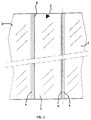
- the door 1 is adapted to be applied for instance to a sanitary appliance such as a shower booth, comprising preferably fixed side walls 2 between which there is provided at least an access aperture adapted to be closed by means of the same door.
- the door 1 comprises at least a preferably square-shaped leaf 3 having a cross-section that may be either plane, ie. straight, or substantially curvilinear.
- the leaf 3 is adapted to co-operate with at least two side jambs 4, as this will be described in greater detail further on.
- profile sections 6 that may for instance be made of aluminium and have preferably a hollow structure, with a cross-section having a preferably curvilinear outer contour.
- the profile sections 6 extend preferably over the whole height of the leaf 3 and further comprise internally a substantially cylindrical portion 5 connected to the outer contour by means of radial ribs 7.
- the profile sections 6 are preferably protruding from the leaf 3 towards the interior of the sanitary appliance.
- the profile sections 6 are equal to each other as far as the cross-section thereof is concerned, and they are mounted on the leaf 3 in a substantially specular manner, so that they are capable of being manufactured in an advantageous manner by starting from just a single type and piece of profile section.
- the door 1 furthermore comprises the afore mentioned side jambs 4, which in a preferred manner are also formed by respective profile sections extending over the full height of the leaf 3.
- the jambs 4 have a cross-section which is substantially in the shape of a G, with a swollen portion 9 in correspondence of which there is provided at least a longitudinal recess 10 adapted to accommodate in a sealing manner, by pressure fitting or bonding it thereto, the edge of a respective wall 2 delimiting the access aperture of the sanitary appliance.
- a shaped portion 11 having a cross-section which is curvilinear or anyway so shaped as to substantially accommodate a respective profile section 6 therewithin, when the door 1 is closed and aligned with the walls 2.
- the jambs 4 are equal to each other as far as the cross-section thereof is concerned, and are further arranged in a substantially specular manner with respect to the door 1, so that they are capable of being manufactured in an advantageous manner by starting from just a single type and piece of profile section.
- any one of said profile sections 6 may be mounted on the sanitary appliance by means of at least a hinging pin (not shown) extending in correspondence of the cylindrical portion 5 of the profile section itself, which is in turn accommodated in the respective jamb 4, as already indicated earlier in this description.
- the door leaf 3 can therefore be opened (outwardly in the example being described here, as shown by the dashed line in Figure 2) by rotating about an axis 12 that extends along the cylindrical portion 5 of one of said profile sections 6.
- the opposite profile section 6 is on the contrary substantially accommodated inside the associated jamb 4 when the door is closed, as this has been already indicated earlier in this description.
- the shaped portions 11 of the jambs 4 are in an advantageous manner adapted to protect the corresponding profile sections 6, with which they form respective labyrinth sealing devices in the door 1, against the water splashes produced inside the sanitary appliance.
- the sealing effect against water splashes seeping out through the door is preferably completed by the provision of a proper set of gaskets.
- a longitudinal lip-sealing gasket 13 adapted to abut (when the door is closed) against the leaf 3. Also such a gasket 13 is in an advantageous manner similar for both jambs 4.
- the profile sections 6 comprise, on the inward facing side thereof, a further longitudinal recess 14 in which there can be mounted (on the non-hinged side of the door only) a corresponding elastic gasket 15 adapted to cooperate with a complementary gasket 16 attached inside the respective jamb 4.
- the jambs 4 also comprise a corresponding attachment longitudinal recess 17 provided in correspondence of the shaped portion 11.
- the gaskets 15 and 16 are of the magnetic profile type and are mounted so as to not only be effective in dampening the closing action of the leaf 3, but also favouring a correct closing thereof by the effect of magnetic attraction.
- each jamb 4 there is preferably provided a further longitudinal recess 18 that is capable of accommodating a corresponding lip-type sealing gasket 19 adapted not only to seal against the respective profile section 6, but also to act as an elastic abutment, ie. a limit stop for the door leaf 3 (on the hinged side of the door) when the door 1 is swung fully open.
- a corresponding lip-type sealing gasket 19 adapted not only to seal against the respective profile section 6, but also to act as an elastic abutment, ie. a limit stop for the door leaf 3 (on the hinged side of the door) when the door 1 is swung fully open.
- the door leaf 3 may be arranged to open inwardly, ie. towards the interior of the sanitary appliance, which in this case is situated below the same leaf, as shown in Figure 2.
Landscapes
- Health & Medical Sciences (AREA)
- Public Health (AREA)
- Epidemiology (AREA)
- General Health & Medical Sciences (AREA)
- Specific Sealing Or Ventilating Devices For Doors And Windows (AREA)
- Orthopedics, Nursing, And Contraception (AREA)
- Absorbent Articles And Supports Therefor (AREA)
- Bidet-Like Cleaning Device And Other Flush Toilet Accessories (AREA)
- Residential Or Office Buildings (AREA)
- Sanitary Device For Flush Toilet (AREA)
- Power-Operated Mechanisms For Wings (AREA)
- Wing Frames And Configurations (AREA)
Abstract
Description
- Figure 1 is a schematical view of a preferred embodiment of the door according to the present invention; and
- Figure 2 is enlarged-scale cross-sectional views of the door shown in Figure 1.
Claims (7)
- Door (1) for a sanitary appliance, or the like, comprising walls (2) between which there is provided at least an access aperture capable of being closed by means of the same door, the latter comprising at least a leaf (3) on the opposite side edges of which there are fixed respective profile sections (6) adapted to cooperate with respective side jambs (4) delimiting said access aperture, characterized in that said profile sections (6) are mutually similar in their cross-section and are mounted on the leaf (3) in a substantially specular or mirror-like manner, said jambs (4) being similar to each other in their cross-section and being arranged in a substantially specular or mirror-like manner with respect to the door (1).
- Door according to claim 1, characterized in that said jambs (4) comprise a first portion (9) which is adapted to be mounted on an edge of a respective wall (2) and from which there departs towards said access aperture a shaped portion (11) adapted to substantially accommodate, when the door (1) is closed, a respective profile section (6) with which it forms a labyrinth-type sealing arrangement.
- Door according to claim 2, characterized in that the profile sections (6) and said shaped portion (11) of the jambs (4) are protruding from the leaf (3) and the walls (2), respectively, towards the interior of the sanitary appliance.
- Door according to claim 1, characterized in that said profile sections (6) are conformed with a substantially cylindrical inner portion (5), one of said profile sections being adapted to be mounted on the sanitary appliance by means of hinging means extending in correspondence of the respective cylindrical portion (5).
- Door according to claim 2, characterized in that said shaped portion (11) of the jambs (4) comprises lip-type longitudinal sealing gasket means (13) adapted to abut against the leaf (3) when the door is closed.
- Door according to claim 2, characterized in that between at least one of the profile sections (6) and the respective jamb (4) there are provided respective longitudinal elastic sealing gasket means (15, 16) of the magnetic profile type.
- Door according to claim 2, characterized in that on said first portion (9) of the jambs (4) there are provided lip-type sealing gasket means (19) adapted to seal against the respective profile section (6) and to act as elastic abutment means for the leaf (3) when the door (1) is swung open.
Applications Claiming Priority (2)
| Application Number | Priority Date | Filing Date | Title |
|---|---|---|---|
| ITPN990038U | 1999-09-27 | ||
| IT1999PN000038U IT248144Y1 (en) | 1999-09-27 | 1999-09-27 | DOOR FOR HYDRO-SANITARY APPLIANCE, OR SIMILAR |
Publications (3)
| Publication Number | Publication Date |
|---|---|
| EP1086644A2 true EP1086644A2 (en) | 2001-03-28 |
| EP1086644A3 EP1086644A3 (en) | 2002-01-30 |
| EP1086644B1 EP1086644B1 (en) | 2005-07-20 |
Family
ID=11395518
Family Applications (1)
| Application Number | Title | Priority Date | Filing Date |
|---|---|---|---|
| EP00116567A Expired - Lifetime EP1086644B1 (en) | 1999-09-27 | 2000-08-01 | Door for sanitary or similar appliance |
Country Status (5)
| Country | Link |
|---|---|
| EP (1) | EP1086644B1 (en) |
| AT (1) | ATE299660T1 (en) |
| DE (1) | DE60021324T2 (en) |
| ES (1) | ES2246205T3 (en) |
| IT (1) | IT248144Y1 (en) |
Cited By (1)
| Publication number | Priority date | Publication date | Assignee | Title |
|---|---|---|---|---|
| EP1554963A3 (en) * | 2004-01-16 | 2005-09-21 | Adamsez (N.I.) Limited | Shower enclosure |
Family Cites Families (3)
| Publication number | Priority date | Publication date | Assignee | Title |
|---|---|---|---|---|
| DE3844486A1 (en) * | 1988-12-31 | 1990-07-05 | Munch Paul Jean | Holding profile for a shower partition wall |
| EP0582873A1 (en) * | 1992-08-08 | 1994-02-16 | Stiemert Duschglas Kg | Shower enclosure |
| DE29504715U1 (en) * | 1995-03-24 | 1995-06-01 | Reichel, Günter, 35232 Dautphetal | Shower partition |
-
1999
- 1999-09-27 IT IT1999PN000038U patent/IT248144Y1/en active
-
2000
- 2000-08-01 DE DE60021324T patent/DE60021324T2/en not_active Expired - Lifetime
- 2000-08-01 AT AT00116567T patent/ATE299660T1/en not_active IP Right Cessation
- 2000-08-01 EP EP00116567A patent/EP1086644B1/en not_active Expired - Lifetime
- 2000-08-01 ES ES00116567T patent/ES2246205T3/en not_active Expired - Lifetime
Cited By (1)
| Publication number | Priority date | Publication date | Assignee | Title |
|---|---|---|---|---|
| EP1554963A3 (en) * | 2004-01-16 | 2005-09-21 | Adamsez (N.I.) Limited | Shower enclosure |
Also Published As
| Publication number | Publication date |
|---|---|
| ES2246205T3 (en) | 2006-02-16 |
| EP1086644A3 (en) | 2002-01-30 |
| EP1086644B1 (en) | 2005-07-20 |
| ITPN990038U1 (en) | 2001-03-27 |
| IT248144Y1 (en) | 2002-12-10 |
| DE60021324D1 (en) | 2005-08-25 |
| ATE299660T1 (en) | 2005-08-15 |
| DE60021324T2 (en) | 2006-04-20 |
Similar Documents
| Publication | Publication Date | Title |
|---|---|---|
| BR9815539A (en) | Container lid | |
| AU2011354119B2 (en) | Built-in electrical household appliance and household appliance assembly and built-in furniture unit for a household appliance | |
| KR20180093073A (en) | Drum washing machine | |
| EP1086644B1 (en) | Door for sanitary or similar appliance | |
| JPH09511898A (en) | Switchboard cabinet | |
| CA2393986A1 (en) | Door boot with reduced opening force | |
| US4462646A (en) | Insulated cabinet construction for chest freezers | |
| CN218092825U (en) | Sealing structure of intelligent oven | |
| AU1760200A (en) | A lid for a cooking appliance | |
| KR100334643B1 (en) | Refrigerator for kimchi | |
| CN213297641U (en) | Heat-insulation door and window profile structure with inner screen window and outer casement window | |
| JP3931515B2 (en) | Waterproofing structure at the entrance / exit of the bathroom unit | |
| RU2006123544A (en) | TARE KIT | |
| CN222066524U (en) | Door body and cooking equipment | |
| CN220267550U (en) | Door sealing structure and integrated kitchen thereof | |
| CN210575607U (en) | Metal switch box with waterproof function | |
| KR200227236Y1 (en) | Compact | |
| CN211270584U (en) | Dish washing machine | |
| JPH10108307A (en) | Water drip packing of outdoor box | |
| CN224078979U (en) | A waterproof folding door and household appliances | |
| KR102324309B1 (en) | Waterproof Structure of Floor Hinge Strengthened with Waterproofing Function | |
| JPS6346614Y2 (en) | ||
| CN211583012U (en) | Door body structure and household appliance | |
| KR200315359Y1 (en) | Opening and shutting stucture for food container | |
| KR200187444Y1 (en) | A Box of floorhinge |
Legal Events
| Date | Code | Title | Description |
|---|---|---|---|
| PUAI | Public reference made under article 153(3) epc to a published international application that has entered the european phase |
Free format text: ORIGINAL CODE: 0009012 |
|
| AK | Designated contracting states |
Kind code of ref document: A2 Designated state(s): AT BE CH CY DE DK ES FI FR GB GR IE IT LI LU MC NL PT SE |
|
| AX | Request for extension of the european patent |
Free format text: AL;LT;LV;MK;RO;SI |
|
| PUAL | Search report despatched |
Free format text: ORIGINAL CODE: 0009013 |
|
| AK | Designated contracting states |
Kind code of ref document: A3 Designated state(s): AT BE CH CY DE DK ES FI FR GB GR IE IT LI LU MC NL PT SE |
|
| AX | Request for extension of the european patent |
Free format text: AL;LT;LV;MK;RO;SI |
|
| 17P | Request for examination filed |
Effective date: 20020312 |
|
| AKX | Designation fees paid |
Free format text: AT BE CH CY DE DK ES FI FR GB GR IE IT LI LU MC NL PT SE |
|
| RAP1 | Party data changed (applicant data changed or rights of an application transferred) |
Owner name: DOMINO S.R.L. |
|
| GRAP | Despatch of communication of intention to grant a patent |
Free format text: ORIGINAL CODE: EPIDOSNIGR1 |
|
| GRAS | Grant fee paid |
Free format text: ORIGINAL CODE: EPIDOSNIGR3 |
|
| GRAA | (expected) grant |
Free format text: ORIGINAL CODE: 0009210 |
|
| AK | Designated contracting states |
Kind code of ref document: B1 Designated state(s): AT BE CH CY DE DK ES FI FR GB GR IE IT LI LU MC NL PT SE |
|
| PG25 | Lapsed in a contracting state [announced via postgrant information from national office to epo] |
Ref country code: BE Free format text: LAPSE BECAUSE OF FAILURE TO SUBMIT A TRANSLATION OF THE DESCRIPTION OR TO PAY THE FEE WITHIN THE PRESCRIBED TIME-LIMIT Effective date: 20050720 Ref country code: AT Free format text: LAPSE BECAUSE OF FAILURE TO SUBMIT A TRANSLATION OF THE DESCRIPTION OR TO PAY THE FEE WITHIN THE PRESCRIBED TIME-LIMIT Effective date: 20050720 Ref country code: NL Free format text: LAPSE BECAUSE OF FAILURE TO SUBMIT A TRANSLATION OF THE DESCRIPTION OR TO PAY THE FEE WITHIN THE PRESCRIBED TIME-LIMIT Effective date: 20050720 Ref country code: CH Free format text: LAPSE BECAUSE OF FAILURE TO SUBMIT A TRANSLATION OF THE DESCRIPTION OR TO PAY THE FEE WITHIN THE PRESCRIBED TIME-LIMIT Effective date: 20050720 Ref country code: LI Free format text: LAPSE BECAUSE OF FAILURE TO SUBMIT A TRANSLATION OF THE DESCRIPTION OR TO PAY THE FEE WITHIN THE PRESCRIBED TIME-LIMIT Effective date: 20050720 Ref country code: FI Free format text: LAPSE BECAUSE OF FAILURE TO SUBMIT A TRANSLATION OF THE DESCRIPTION OR TO PAY THE FEE WITHIN THE PRESCRIBED TIME-LIMIT Effective date: 20050720 |
|
| REG | Reference to a national code |
Ref country code: GB Ref legal event code: FG4D |
|
| REG | Reference to a national code |
Ref country code: CH Ref legal event code: EP |
|
| PG25 | Lapsed in a contracting state [announced via postgrant information from national office to epo] |
Ref country code: LU Free format text: LAPSE BECAUSE OF NON-PAYMENT OF DUE FEES Effective date: 20050801 Ref country code: CY Free format text: LAPSE BECAUSE OF FAILURE TO SUBMIT A TRANSLATION OF THE DESCRIPTION OR TO PAY THE FEE WITHIN THE PRESCRIBED TIME-LIMIT Effective date: 20050801 |
|
| PG25 | Lapsed in a contracting state [announced via postgrant information from national office to epo] |
Ref country code: IE Free format text: LAPSE BECAUSE OF NON-PAYMENT OF DUE FEES Effective date: 20050802 |
|
| REG | Reference to a national code |
Ref country code: IE Ref legal event code: FG4D |
|
| REF | Corresponds to: |
Ref document number: 60021324 Country of ref document: DE Date of ref document: 20050825 Kind code of ref document: P |
|
| PG25 | Lapsed in a contracting state [announced via postgrant information from national office to epo] |
Ref country code: MC Free format text: LAPSE BECAUSE OF NON-PAYMENT OF DUE FEES Effective date: 20050831 |
|
| PG25 | Lapsed in a contracting state [announced via postgrant information from national office to epo] |
Ref country code: GB Free format text: LAPSE BECAUSE OF NON-PAYMENT OF DUE FEES Effective date: 20051020 Ref country code: SE Free format text: LAPSE BECAUSE OF FAILURE TO SUBMIT A TRANSLATION OF THE DESCRIPTION OR TO PAY THE FEE WITHIN THE PRESCRIBED TIME-LIMIT Effective date: 20051020 Ref country code: GR Free format text: LAPSE BECAUSE OF FAILURE TO SUBMIT A TRANSLATION OF THE DESCRIPTION OR TO PAY THE FEE WITHIN THE PRESCRIBED TIME-LIMIT Effective date: 20051020 Ref country code: DK Free format text: LAPSE BECAUSE OF FAILURE TO SUBMIT A TRANSLATION OF THE DESCRIPTION OR TO PAY THE FEE WITHIN THE PRESCRIBED TIME-LIMIT Effective date: 20051020 |
|
| PG25 | Lapsed in a contracting state [announced via postgrant information from national office to epo] |
Ref country code: PT Free format text: LAPSE BECAUSE OF FAILURE TO SUBMIT A TRANSLATION OF THE DESCRIPTION OR TO PAY THE FEE WITHIN THE PRESCRIBED TIME-LIMIT Effective date: 20051221 |
|
| REG | Reference to a national code |
Ref country code: CH Ref legal event code: PL |
|
| NLV1 | Nl: lapsed or annulled due to failure to fulfill the requirements of art. 29p and 29m of the patents act | ||
| REG | Reference to a national code |
Ref country code: ES Ref legal event code: FG2A Ref document number: 2246205 Country of ref document: ES Kind code of ref document: T3 |
|
| ET | Fr: translation filed | ||
| REG | Reference to a national code |
Ref country code: FR Ref legal event code: GC |
|
| REG | Reference to a national code |
Ref country code: IE Ref legal event code: MM4A |
|
| PLBE | No opposition filed within time limit |
Free format text: ORIGINAL CODE: 0009261 |
|
| STAA | Information on the status of an ep patent application or granted ep patent |
Free format text: STATUS: NO OPPOSITION FILED WITHIN TIME LIMIT |
|
| 26N | No opposition filed |
Effective date: 20060421 |
|
| GBPC | Gb: european patent ceased through non-payment of renewal fee |
Effective date: 20051020 |
|
| PGFP | Annual fee paid to national office [announced via postgrant information from national office to epo] |
Ref country code: ES Payment date: 20060807 Year of fee payment: 7 |
|
| REG | Reference to a national code |
Ref country code: ES Ref legal event code: FD2A Effective date: 20070802 |
|
| PG25 | Lapsed in a contracting state [announced via postgrant information from national office to epo] |
Ref country code: ES Free format text: LAPSE BECAUSE OF NON-PAYMENT OF DUE FEES Effective date: 20070802 |
|
| PGFP | Annual fee paid to national office [announced via postgrant information from national office to epo] |
Ref country code: IT Payment date: 20100708 Year of fee payment: 11 Ref country code: FR Payment date: 20100901 Year of fee payment: 11 Ref country code: DE Payment date: 20100823 Year of fee payment: 11 |
|
| REG | Reference to a national code |
Ref country code: FR Ref legal event code: ST Effective date: 20120430 |
|
| PG25 | Lapsed in a contracting state [announced via postgrant information from national office to epo] |
Ref country code: IT Free format text: LAPSE BECAUSE OF NON-PAYMENT OF DUE FEES Effective date: 20110801 |
|
| REG | Reference to a national code |
Ref country code: DE Ref legal event code: R119 Ref document number: 60021324 Country of ref document: DE Effective date: 20120301 |
|
| PG25 | Lapsed in a contracting state [announced via postgrant information from national office to epo] |
Ref country code: FR Free format text: LAPSE BECAUSE OF NON-PAYMENT OF DUE FEES Effective date: 20110831 |
|
| PG25 | Lapsed in a contracting state [announced via postgrant information from national office to epo] |
Ref country code: DE Free format text: LAPSE BECAUSE OF NON-PAYMENT OF DUE FEES Effective date: 20120301 |