EP1085676B1 - Method of controlling power in a point to multipoint communication network and system for carrying out said method - Google Patents
Method of controlling power in a point to multipoint communication network and system for carrying out said method Download PDFInfo
- Publication number
- EP1085676B1 EP1085676B1 EP99402269.7A EP99402269A EP1085676B1 EP 1085676 B1 EP1085676 B1 EP 1085676B1 EP 99402269 A EP99402269 A EP 99402269A EP 1085676 B1 EP1085676 B1 EP 1085676B1
- Authority
- EP
- European Patent Office
- Prior art keywords
- receiver means
- transmitter
- signal
- signals
- receiver
- Prior art date
- Legal status (The legal status is an assumption and is not a legal conclusion. Google has not performed a legal analysis and makes no representation as to the accuracy of the status listed.)
- Expired - Lifetime
Links
- 238000000034 method Methods 0.000 title claims description 14
- 238000004891 communication Methods 0.000 title claims description 10
- 230000005540 biological transmission Effects 0.000 claims description 30
- 238000005259 measurement Methods 0.000 description 4
- 125000004122 cyclic group Chemical group 0.000 description 1
- 230000006866 deterioration Effects 0.000 description 1
- 238000010586 diagram Methods 0.000 description 1
- 238000005562 fading Methods 0.000 description 1
- 238000010295 mobile communication Methods 0.000 description 1
Images
Classifications
-
- H—ELECTRICITY
- H04—ELECTRIC COMMUNICATION TECHNIQUE
- H04W—WIRELESS COMMUNICATION NETWORKS
- H04W52/00—Power management, e.g. Transmission Power Control [TPC] or power classes
- H04W52/04—Transmission power control [TPC]
- H04W52/18—TPC being performed according to specific parameters
- H04W52/24—TPC being performed according to specific parameters using SIR [Signal to Interference Ratio] or other wireless path parameters
Definitions
- the present invention relates to a method of controlling power in a transmission link between a central station and a terminal in a point to multi-point communication network and system for carrying out said method.
- the present invention is suitable for implementation in satellite access networks or terrestrial point to multi-point access networks.
- the invention relates to controlling power in communication between a transmitter such as a central station and terminals receiving such communication, which permit the compensation of power loss caused by the diverse phenomena present on the way of the signal propagation.
- multi-path signals may be obstacles present on the propagation path of the signal which cause the signal to be reflected from them and thus give rise to signals traveling on various paths, or the so called multi-path signals.
- An important negative consequence caused by the presence of multi-path signals is the effect known as fading in which signals transmitted through different paths are received in different phases and therefore tend to cancel each other in amplitude.
- a further effect in power loss variation could be caused by the distance variation from the base station, or from the terminal to the satellite when the terminal and/or the satellite are moving. It is known that the larger said distance is, the higher the power loss would be in the signal. Overcoming these effects in conventional manners would require costly solutions and limits the resources of the whole system.
- a widely used known solution consists of adjusting the power, link by link, or connection by connection. The terminal station performs in a continuous manner a measurement of the quality of the data received. Said measurement is then communicated to the central station. The central station would then adjust the power of transmission depending upon the information received from the terminal.
- the above solution has the drawback that when traffic links transmit the data in a sporadic manner - which is a situation which may occur for example in Internet traffic, voice transmission using silence intervals, or the like - it may happen that a traffic link remains inactive during a relatively long period of time due to the presence of the aforementioned transmission phenomena, thus making said measurement impossible or inaccurate.
- a solution to this problem may consist of forcing a cyclic emission in the central station during said silence periods; however this approach would cause loss of resources in the transmission system.
- the terminal performs a quality calibration over the signal broadcast from the central station.
- An example of calibration could consist of measuring the bit error rate of the signal to noise ratio.
- the dynamic of the power control is important, it could turn out to be difficult, or even impossible to determine with good accuracy, the quality of the received signal when its level is too high. This situation may occur when a reference signal is emitted at strong levels so that it can be received by all the terminals, including under unfavorable propagation conditions.
- An uplink channel transmission power control method is provided for a CDMA mobile communication system is known from EP-A-0 847 147 .
- a base station measures a level of data transmitted from each one of a plurality of mobile terminals at each channel, and generates a transmission power control signal of each uplink traffic channel.
- the generated transmission power control signals are multiplexed, and the multiplexed common transmission power control signal is transmitted to all mobile terminals by using the common channel shared by the mobile terminals.
- Each mobile terminal derives the transmission power control signal of the uplink traffic channel used by the terminal, from the received common transmission power control signal, and controls the transmission power of a data packet. Therefore, according to this document, it is the mobile terminal that controls the transmission power.
- the method of controlling power in a transmission link between a transmitter and a receiver in a point to multi-point communication network and system for carrying out said method are proposed by the present invention.
- One object of the present invention is that of providing a method according to claim 1.
- said quality of each reference signal is expressed in terms of signal to noise ratio or other known means.
- the indication of the reference signal corresponding to the receiver means is made by transmitting a return signal from the receiver means to the transmitter means.
- the return signal indicated by the receiver means to the transmitter means may be computed from the received reference signals.
- Another object of the present invention is that of providing a transmitter means according to claim 6.
- a further object of the present invention is that of providing a receiver means according to claim 9.
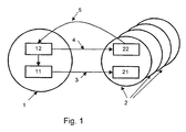
- Figure 1 is a schematic diagram of a communication network system for carrying out the method of the present invention.
- a communication network comprising at least one transmitter means 1 such as a central station, and a plurality of terminal stations comprising receiver means 2 such as a fixed or mobile termination.
- Each transmitter means 1 comprises, inter alia , traffic transmitter means 11 and reference signal transmitter means 12.
- Each receiver means 2 comprises, inter alia , traffic receiver means 21 and reference signal receiver means 22.
- a transmitter means 1 capable of transmitting traffic data 3 from a traffic transmitter means 11 included therein, to a plurality of receiver means 2, either mobile or fixed, said transmission having a power level which is at a minimum level, but sufficient for ensuring that the quality of the service required is guaranteed, such quality being expressed in known manners such as in terms of signal to noise ratio or other known means.
- the reference signal transmitter 12 of the transmitter means 1 transmits a signal, as a reference signal 4 which serves as a scale for controlling the quality (power level) of the traffic data being transmitted.
- Said reference signal 4 is transmitted in any convenient manner such as periodically, continuously, or even randomly, from said transmitter 1, and is received at the reference signal receiver means 22 of the receiver means 2.
- the transmitter means transmits a plurality of said reference signals 4, corresponding to a plurality of receiver means 2.
- the power level of said signals 4 are measured by the reference signal receiver means 22. As this measurement is made over a plurality of reference signals, it thus permits each terminal to determine its corresponding reference signal 4. Having determined said corresponding reference signal 4, the receiver means 2 then transmits a return signal 5 to the transmitter means 1, indicating the reference signal 4 corresponding to that particular terminal. The transmitter means 1 in turn, adjusts, if required, the corresponding power level of the signal in the following manner. When the reference signal transmitter 12 receives said return signal 5, it sends an indication to the traffic transmitter means 11 which in turn performs the adjustment in the transmission power level.
- each receiver means 2 can send the return signal 5 to the transmitter means 1, periodically and/or upon a change produced in the quality of the received signal 4. Using this information, the transmitter 1 can then adjust the level of the power of transmission towards each terminal, having regard to the quality of the service provided in each connection.
- the traffic data 3 transmitted by the transmitter 1 to different terminals, i.e. receiver means, are also received by other terminals. Therefore, said traffic data 3 as such may also be used totally or partly as reference signals.
Landscapes
- Engineering & Computer Science (AREA)
- Computer Networks & Wireless Communication (AREA)
- Signal Processing (AREA)
- Mobile Radio Communication Systems (AREA)
- Radio Relay Systems (AREA)
- Transceivers (AREA)
- Small-Scale Networks (AREA)
- Transmitters (AREA)
Description
- The present invention relates to a method of controlling power in a transmission link between a central station and a terminal in a point to multi-point communication network and system for carrying out said method. The present invention is suitable for implementation in satellite access networks or terrestrial point to multi-point access networks.
- Particularly the invention relates to controlling power in communication between a transmitter such as a central station and terminals receiving such communication, which permit the compensation of power loss caused by the diverse phenomena present on the way of the signal propagation.
- As it is well known in the field of telecommunications, when a signal is transmitted from a transmitter station via radio to a receiver station, different phenomena present on its propagation path may affect the quality of the signal received at the receiver end.
- One example of such phenomena may be obstacles present on the propagation path of the signal which cause the signal to be reflected from them and thus give rise to signals traveling on various paths, or the so called multi-path signals. An important negative consequence caused by the presence of multi-path signals is the effect known as fading in which signals transmitted through different paths are received in different phases and therefore tend to cancel each other in amplitude.
- Rain, storm or other similar natural disturbances are further examples of phenomena giving rise to signal deterioration. A further effect in power loss variation could be caused by the distance variation from the base station, or from the terminal to the satellite when the terminal and/or the satellite are moving. It is known that the larger said distance is, the higher the power loss would be in the signal. Overcoming these effects in conventional manners would require costly solutions and limits the resources of the whole system. A widely used known solution consists of adjusting the power, link by link, or connection by connection. The terminal station performs in a continuous manner a measurement of the quality of the data received. Said measurement is then communicated to the central station. The central station would then adjust the power of transmission depending upon the information received from the terminal.
- The above solution has the drawback that when traffic links transmit the data in a sporadic manner - which is a situation which may occur for example in Internet traffic, voice transmission using silence intervals, or the like - it may happen that a traffic link remains inactive during a relatively long period of time due to the presence of the aforementioned transmission phenomena, thus making said measurement impossible or inaccurate. A solution to this problem may consist of forcing a cyclic emission in the central station during said silence periods; however this approach would cause loss of resources in the transmission system.
- According to another known solution the terminal performs a quality calibration over the signal broadcast from the central station. An example of calibration could consist of measuring the bit error rate of the signal to noise ratio. However if the dynamic of the power control is important, it could turn out to be difficult, or even impossible to determine with good accuracy, the quality of the received signal when its level is too high. This situation may occur when a reference signal is emitted at strong levels so that it can be received by all the terminals, including under unfavorable propagation conditions.
- An uplink channel transmission power control method is provided for a CDMA mobile communication system is known from
EP-A-0 847 147 . According to the teaching of this documents, a base station measures a level of data transmitted from each one of a plurality of mobile terminals at each channel, and generates a transmission power control signal of each uplink traffic channel. The generated transmission power control signals are multiplexed, and the multiplexed common transmission power control signal is transmitted to all mobile terminals by using the common channel shared by the mobile terminals. Each mobile terminal derives the transmission power control signal of the uplink traffic channel used by the terminal, from the received common transmission power control signal, and controls the transmission power of a data packet. Therefore, according to this document, it is the mobile terminal that controls the transmission power. - Therefore it is desired to compensate the effects caused by the phenomena present on the transmission path of the signal, while at the same time the use of the resources of the transmission system is optimized. In order to obtain the desired solution it would be necessary to control the transmission power.
- In order to overcome the above disadvantages, the method of controlling power in a transmission link between a transmitter and a receiver in a point to multi-point communication network and system for carrying out said method are proposed by the present invention.
- One object of the present invention is that of providing a method according to
claim 1. - According to the invention, said quality of each reference signal is expressed in terms of signal to noise ratio or other known means.
- The indication of the reference signal corresponding to the receiver means is made by transmitting a return signal from the receiver means to the transmitter means.
- Further, in order to increase the accuracy and to limit the number of transmitted signals, the return signal indicated by the receiver means to the transmitter means may be computed from the received reference signals. Another object of the present invention is that of providing a transmitter means according to claim 6.
- A further object of the present invention is that of providing a receiver means according to claim 9.
- The above and further embodiments of the present invention are described in further detail hereinbelow as well as in the claims.
-
Figure 1 is a schematic diagram of a communication network system for carrying out the method of the present invention. - Referring to
figure 1 , there is provided a communication network comprising at least one transmitter means 1 such as a central station, and a plurality of terminal stations comprising receiver means 2 such as a fixed or mobile termination. Each transmitter means 1 comprises, inter alia, traffic transmitter means 11 and reference signal transmitter means 12. Each receiver means 2 comprises, inter alia, traffic receiver means 21 and reference signal receiver means 22. - With the above arrangement taken as a non-limiting example of the invention, a transmitter means 1 is described capable of transmitting
traffic data 3 from a traffic transmitter means 11 included therein, to a plurality of receiver means 2, either mobile or fixed, said transmission having a power level which is at a minimum level, but sufficient for ensuring that the quality of the service required is guaranteed, such quality being expressed in known manners such as in terms of signal to noise ratio or other known means. Additionally thereference signal transmitter 12 of the transmitter means 1, transmits a signal, as areference signal 4 which serves as a scale for controlling the quality (power level) of the traffic data being transmitted. Saidreference signal 4 is transmitted in any convenient manner such as periodically, continuously, or even randomly, from saidtransmitter 1, and is received at the reference signal receiver means 22 of the receiver means 2. In practice, the transmitter means transmits a plurality of saidreference signals 4, corresponding to a plurality of receiver means 2. - Once the reference signals are received at a
receiver end 2, the power level ofsaid signals 4 are measured by the reference signal receiver means 22. As this measurement is made over a plurality of reference signals, it thus permits each terminal to determine itscorresponding reference signal 4. Having determined saidcorresponding reference signal 4, the receiver means 2 then transmits areturn signal 5 to the transmitter means 1, indicating thereference signal 4 corresponding to that particular terminal. The transmitter means 1 in turn, adjusts, if required, the corresponding power level of the signal in the following manner. When thereference signal transmitter 12 receives saidreturn signal 5, it sends an indication to the traffic transmitter means 11 which in turn performs the adjustment in the transmission power level. - At the receiving side, each receiver means 2 can send the
return signal 5 to the transmitter means 1, periodically and/or upon a change produced in the quality of the receivedsignal 4. Using this information, thetransmitter 1 can then adjust the level of the power of transmission towards each terminal, having regard to the quality of the service provided in each connection. - It is to be noted that the
traffic data 3 transmitted by thetransmitter 1 to different terminals, i.e. receiver means, are also received by other terminals. Therefore, saidtraffic data 3 as such may also be used totally or partly as reference signals.
Claims (9)
- Method of controlling power in a transmission link between a transmitter means (1) and a receiver means (2) in a point to multipoint communication network, said network comprising at least one transmitter means (1) transmitting traffic data (3) to a plurality of receiver means (2), characterized in comprising the steps of:- said at least one transmitter means (1) transmitting a plurality of reference signals (4) to said plurality of receiver means (2); each reference signal (4) having a transmission quality corresponding to at least one receiver means (2);- each receiver means (2) receiving said plurality of reference signals (4) and measuring their respective transmission quality so as to determine a reference signal (4) corresponding to said receiver means (2);- each receiver means (2) transmitting a signal to said at least one transmitter means (1), for indicating the reference signal (4) corresponding thereto; and when the indication received from said receiver means (2) so requires,- said at least one transmitter means (1) adjusting the power level of transmission of said traffic data (3).
- Method according to claim 1, characterized in that said quality of each reference signal is expressed in terms of signal to noise ratio.
- Method according to any of the preceding claims, characterized in that the indication of the reference signal (4) corresponding to the receiver means (2) is made by transmitting a return signal (5) from the receiver means (2) to the transmitter means (1).
- Method according to claim 3, characterized in that the return signal (5) is determined from the received reference signals (4).
- Method according to claim 1, characterized in that, said traffic data (3) is used totally or partly as reference signals (4).
- Transmitter means adapted for controlling power in a transmission link between said transmitter means and a receiver means in a point to multipoint communication network, said network comprising said transmitter means for transmitting traffic data to a plurality of receiver means (2), characterized in that said transmitter means (1) is adapted for transmitting a plurality of reference signals (4) to a plurality of receiver means (2), each reference signal (4) having a transmission quality corresponding to at least one receiver means (2); for receiving signals (5) transmitted from at least one receiver means (2), said signals (5) being indicative of a reference signal (4) corresponding to said receiver means (2) and for adjusting a power level of transmission of traffic data (3) based on said signals (5).
- Transmitter means according to claim 5, characterized in that said quality of each reference signal is expressed in terms of signal to noise ratio.
- Central station, including the transmitter means of claim 6.
- Receiver means for use in a transmission link in a point to multipoint communication network, said network further comprising at least one transmitter means (1) for transmitting traffic data (3), characterized in that said receiver means (2) is adapted for receiving a plurality of reference signals (4) from said at least one transmitter means (1), at least one of said reference signals (4) having a transmission quality corresponding to said receiver means (2); for measuring said transmission quality of said at last one of said reference signals, and for transmitting signals (5) from said receiver means (2) to said at least one transmitter means, said signals (5) being indicative of said reference signal (4) corresponding to said receiver means (2).
Priority Applications (3)
| Application Number | Priority Date | Filing Date | Title |
|---|---|---|---|
| EP99402269.7A EP1085676B1 (en) | 1999-09-16 | 1999-09-16 | Method of controlling power in a point to multipoint communication network and system for carrying out said method |
| JP2000262268A JP2001144784A (en) | 1999-09-16 | 2000-08-31 | Method for controlling power in a transmission link between a transmitter and a receiver in a point-to-multipoint communication network and a system for performing said method |
| US09/659,606 US6650906B1 (en) | 1999-09-16 | 2000-09-11 | Method of controlling power in a transmission link between a transmitter and a receiver in a point to multi-point communication network and system for carrying out said method |
Applications Claiming Priority (1)
| Application Number | Priority Date | Filing Date | Title |
|---|---|---|---|
| EP99402269.7A EP1085676B1 (en) | 1999-09-16 | 1999-09-16 | Method of controlling power in a point to multipoint communication network and system for carrying out said method |
Publications (2)
| Publication Number | Publication Date |
|---|---|
| EP1085676A1 EP1085676A1 (en) | 2001-03-21 |
| EP1085676B1 true EP1085676B1 (en) | 2014-10-22 |
Family
ID=8242113
Family Applications (1)
| Application Number | Title | Priority Date | Filing Date |
|---|---|---|---|
| EP99402269.7A Expired - Lifetime EP1085676B1 (en) | 1999-09-16 | 1999-09-16 | Method of controlling power in a point to multipoint communication network and system for carrying out said method |
Country Status (3)
| Country | Link |
|---|---|
| US (1) | US6650906B1 (en) |
| EP (1) | EP1085676B1 (en) |
| JP (1) | JP2001144784A (en) |
Families Citing this family (8)
| Publication number | Priority date | Publication date | Assignee | Title |
|---|---|---|---|---|
| SG109450A1 (en) * | 2000-04-06 | 2005-03-30 | Ntt Docomo Inc | Multicast signal transmission power control method and base station using the same |
| JP3838487B2 (en) * | 2001-08-10 | 2006-10-25 | 株式会社エヌ・ティ・ティ・ドコモ | Radio communication system, communication terminal apparatus, base station apparatus, and transmission power control method |
| JP4084683B2 (en) * | 2003-03-04 | 2008-04-30 | 株式会社エヌ・ティ・ティ・ドコモ | Mobile communication system, radio control apparatus, base station, and transmission power control method |
| FR2856862B1 (en) * | 2003-06-27 | 2005-09-09 | Nortel Networks Ltd | METHOD FOR CONTROLLING RELATIVE POWER OF RADIO SIGNALS EMITTED IN MACRODIVERSITY MODE, AND RADIO NETWORK CONTROLLER FOR IMPLEMENTING THE METHOD |
| GB0327041D0 (en) * | 2003-11-21 | 2003-12-24 | Roke Manor Research | Apparatus and methods |
| GB0721307D0 (en) * | 2007-10-30 | 2007-12-12 | Nokia Siemens Networks Oy | Measuring apparatus |
| JP5107069B2 (en) * | 2008-01-25 | 2012-12-26 | 株式会社エヌ・ティ・ティ・ドコモ | Base station apparatus and method used in mobile communication system |
| JP6135771B2 (en) * | 2013-10-25 | 2017-05-31 | 富士通株式会社 | Communication system, communication terminal, and reference signal transmission method |
Family Cites Families (7)
| Publication number | Priority date | Publication date | Assignee | Title |
|---|---|---|---|---|
| JPH08256102A (en) * | 1995-01-19 | 1996-10-01 | Sony Corp | Cellular system |
| AU3260195A (en) * | 1995-08-31 | 1997-03-19 | Nokia Telecommunications Oy | Method and device for controlling transmission power of a radio transmitter in a cellular communication system |
| JPH10173594A (en) * | 1996-12-06 | 1998-06-26 | Hitachi Ltd | Code division multiple access communication system and transmission power control method |
| US6212397B1 (en) * | 1996-12-23 | 2001-04-03 | Texas Instruments Incorporated | Method and system for controlling remote multipoint stations |
| US6253077B1 (en) * | 1997-05-16 | 2001-06-26 | Texas Instruments Incorporated | Downstream power control in point-to-multipoint systems |
| US6408165B1 (en) * | 1999-07-06 | 2002-06-18 | Cisco Technology, Inc. | Power regulation using multi-loop control |
| US6285886B1 (en) * | 1999-07-08 | 2001-09-04 | Lucent Technologies Inc. | Method for controlling power for a communications system having multiple traffic channels per subscriber |
-
1999
- 1999-09-16 EP EP99402269.7A patent/EP1085676B1/en not_active Expired - Lifetime
-
2000
- 2000-08-31 JP JP2000262268A patent/JP2001144784A/en not_active Withdrawn
- 2000-09-11 US US09/659,606 patent/US6650906B1/en not_active Expired - Lifetime
Also Published As
| Publication number | Publication date |
|---|---|
| EP1085676A1 (en) | 2001-03-21 |
| JP2001144784A (en) | 2001-05-25 |
| US6650906B1 (en) | 2003-11-18 |
Similar Documents
| Publication | Publication Date | Title |
|---|---|---|
| US5511079A (en) | Apparatus and method for controlling forward error correction encoding in a very small aperture terminal | |
| US7599658B1 (en) | Method for uplink power control for distributed satellite networks to compensate for rain fade | |
| RU2221340C2 (en) | Method and device for controlling transmission power in communication system | |
| US6961316B2 (en) | Mobile communication system having adaptively assigned packet rate | |
| US6473624B1 (en) | Determining a reference power level for diversity handover base stations | |
| US6535723B1 (en) | Method of power control for a wireless communication system having multiple information rates | |
| US8199721B2 (en) | Method and system for selecting relay station in a communication system | |
| EP1641142A1 (en) | Power adaptation in a multi-station network | |
| US6314090B1 (en) | Method of perch channel transmission and cell selection in CDMA mobile communication system | |
| WO1998056120A8 (en) | Transmit power control in a radio communication system | |
| CN1953346A (en) | Weighted open loop power control in a time division duplex communication system | |
| EP0607359A1 (en) | Transmitter power control system | |
| EP1129528B1 (en) | Transmission diversity | |
| US6760566B1 (en) | Method and apparatus for controlling a transmission power threshold of a satellite communication system | |
| US6650906B1 (en) | Method of controlling power in a transmission link between a transmitter and a receiver in a point to multi-point communication network and system for carrying out said method | |
| US8009096B2 (en) | Method, system and apparatus for determining antenna weighting for transmit diversity | |
| DE60214886D1 (en) | PARAMETER ESTIMATE FOR ADAPTIVE ANTENNA SYSTEM | |
| US8437704B2 (en) | System and method for resuming power control after interruption | |
| JP3583730B2 (en) | Wireless communication system and wireless transmission device | |
| EP3735050A1 (en) | Gateway managed terminal uplink power control | |
| KR20070055537A (en) | Wireless communication system, radio station, and method for transmitting data | |
| KR100516536B1 (en) | Method for data transmission with double tx antennas in turn of forward link | |
| RU2172067C2 (en) | Method and device to control power in mobile communication system | |
| JPS62178024A (en) | Transmission power controller for satellite communication earth station | |
| JPH05284071A (en) | Transmission power control system |
Legal Events
| Date | Code | Title | Description |
|---|---|---|---|
| PUAI | Public reference made under article 153(3) epc to a published international application that has entered the european phase |
Free format text: ORIGINAL CODE: 0009012 |
|
| AK | Designated contracting states |
Kind code of ref document: A1 Designated state(s): AT BE CH CY DE DK ES FI FR GB GR IE IT LI LU MC NL PT SE |
|
| AX | Request for extension of the european patent |
Free format text: AL;LT;LV;MK;RO;SI |
|
| 17P | Request for examination filed |
Effective date: 20010921 |
|
| AKX | Designation fees paid |
Free format text: AT BE CH CY DE DK ES FI FR GB GR IE IT LI LU MC NL PT SE |
|
| RAP1 | Party data changed (applicant data changed or rights of an application transferred) |
Owner name: ALCATEL LUCENT |
|
| 17Q | First examination report despatched |
Effective date: 20070828 |
|
| RAP1 | Party data changed (applicant data changed or rights of an application transferred) |
Owner name: ALCATEL LUCENT |
|
| 111Z | Information provided on other rights and legal means of execution |
Free format text: AT BE CH CY DE DK ES FI FR GB GR IE IT LI LU MC NL PT SE Effective date: 20130410 |
|
| REG | Reference to a national code |
Ref country code: DE Ref legal event code: R079 Ref document number: 69945198 Country of ref document: DE Free format text: PREVIOUS MAIN CLASS: H04B0007005000 Ipc: H04W0052240000 |
|
| GRAP | Despatch of communication of intention to grant a patent |
Free format text: ORIGINAL CODE: EPIDOSNIGR1 |
|
| RIC1 | Information provided on ipc code assigned before grant |
Ipc: H04W 52/24 20090101AFI20140326BHEP |
|
| INTG | Intention to grant announced |
Effective date: 20140424 |
|
| RAP1 | Party data changed (applicant data changed or rights of an application transferred) |
Owner name: ALCATEL LUCENT |
|
| GRAS | Grant fee paid |
Free format text: ORIGINAL CODE: EPIDOSNIGR3 |
|
| GRAA | (expected) grant |
Free format text: ORIGINAL CODE: 0009210 |
|
| AK | Designated contracting states |
Kind code of ref document: B1 Designated state(s): AT BE CH CY DE DK ES FI FR GB GR IE IT LI LU MC NL PT SE |
|
| REG | Reference to a national code |
Ref country code: GB Ref legal event code: FG4D |
|
| REG | Reference to a national code |
Ref country code: CH Ref legal event code: EP |
|
| REG | Reference to a national code |
Ref country code: AT Ref legal event code: REF Ref document number: 693095 Country of ref document: AT Kind code of ref document: T Effective date: 20141115 |
|
| D11X | Information provided on other rights and legal means of execution (deleted) | ||
| REG | Reference to a national code |
Ref country code: IE Ref legal event code: FG4D |
|
| REG | Reference to a national code |
Ref country code: DE Ref legal event code: R096 Ref document number: 69945198 Country of ref document: DE Effective date: 20141204 |
|
| REG | Reference to a national code |
Ref country code: NL Ref legal event code: VDEP Effective date: 20141022 |
|
| REG | Reference to a national code |
Ref country code: AT Ref legal event code: MK05 Ref document number: 693095 Country of ref document: AT Kind code of ref document: T Effective date: 20141022 |
|
| PG25 | Lapsed in a contracting state [announced via postgrant information from national office to epo] |
Ref country code: ES Free format text: LAPSE BECAUSE OF FAILURE TO SUBMIT A TRANSLATION OF THE DESCRIPTION OR TO PAY THE FEE WITHIN THE PRESCRIBED TIME-LIMIT Effective date: 20141022 Ref country code: FI Free format text: LAPSE BECAUSE OF FAILURE TO SUBMIT A TRANSLATION OF THE DESCRIPTION OR TO PAY THE FEE WITHIN THE PRESCRIBED TIME-LIMIT Effective date: 20141022 Ref country code: PT Free format text: LAPSE BECAUSE OF FAILURE TO SUBMIT A TRANSLATION OF THE DESCRIPTION OR TO PAY THE FEE WITHIN THE PRESCRIBED TIME-LIMIT Effective date: 20150223 Ref country code: NL Free format text: LAPSE BECAUSE OF FAILURE TO SUBMIT A TRANSLATION OF THE DESCRIPTION OR TO PAY THE FEE WITHIN THE PRESCRIBED TIME-LIMIT Effective date: 20141022 |
|
| PG25 | Lapsed in a contracting state [announced via postgrant information from national office to epo] |
Ref country code: GR Free format text: LAPSE BECAUSE OF FAILURE TO SUBMIT A TRANSLATION OF THE DESCRIPTION OR TO PAY THE FEE WITHIN THE PRESCRIBED TIME-LIMIT Effective date: 20150123 Ref country code: AT Free format text: LAPSE BECAUSE OF FAILURE TO SUBMIT A TRANSLATION OF THE DESCRIPTION OR TO PAY THE FEE WITHIN THE PRESCRIBED TIME-LIMIT Effective date: 20141022 Ref country code: CY Free format text: LAPSE BECAUSE OF FAILURE TO SUBMIT A TRANSLATION OF THE DESCRIPTION OR TO PAY THE FEE WITHIN THE PRESCRIBED TIME-LIMIT Effective date: 20141022 Ref country code: SE Free format text: LAPSE BECAUSE OF FAILURE TO SUBMIT A TRANSLATION OF THE DESCRIPTION OR TO PAY THE FEE WITHIN THE PRESCRIBED TIME-LIMIT Effective date: 20141022 |
|
| REG | Reference to a national code |
Ref country code: DE Ref legal event code: R097 Ref document number: 69945198 Country of ref document: DE |
|
| PG25 | Lapsed in a contracting state [announced via postgrant information from national office to epo] |
Ref country code: DK Free format text: LAPSE BECAUSE OF FAILURE TO SUBMIT A TRANSLATION OF THE DESCRIPTION OR TO PAY THE FEE WITHIN THE PRESCRIBED TIME-LIMIT Effective date: 20141022 |
|
| PLBE | No opposition filed within time limit |
Free format text: ORIGINAL CODE: 0009261 |
|
| STAA | Information on the status of an ep patent application or granted ep patent |
Free format text: STATUS: NO OPPOSITION FILED WITHIN TIME LIMIT |
|
| PG25 | Lapsed in a contracting state [announced via postgrant information from national office to epo] |
Ref country code: IT Free format text: LAPSE BECAUSE OF FAILURE TO SUBMIT A TRANSLATION OF THE DESCRIPTION OR TO PAY THE FEE WITHIN THE PRESCRIBED TIME-LIMIT Effective date: 20141022 |
|
| REG | Reference to a national code |
Ref country code: FR Ref legal event code: PLFP Year of fee payment: 17 |
|
| 26N | No opposition filed |
Effective date: 20150723 |
|
| PG25 | Lapsed in a contracting state [announced via postgrant information from national office to epo] |
Ref country code: LU Free format text: LAPSE BECAUSE OF FAILURE TO SUBMIT A TRANSLATION OF THE DESCRIPTION OR TO PAY THE FEE WITHIN THE PRESCRIBED TIME-LIMIT Effective date: 20150916 Ref country code: MC Free format text: LAPSE BECAUSE OF FAILURE TO SUBMIT A TRANSLATION OF THE DESCRIPTION OR TO PAY THE FEE WITHIN THE PRESCRIBED TIME-LIMIT Effective date: 20141022 |
|
| REG | Reference to a national code |
Ref country code: CH Ref legal event code: PL |
|
| REG | Reference to a national code |
Ref country code: IE Ref legal event code: MM4A |
|
| PG25 | Lapsed in a contracting state [announced via postgrant information from national office to epo] |
Ref country code: IE Free format text: LAPSE BECAUSE OF NON-PAYMENT OF DUE FEES Effective date: 20150916 Ref country code: CH Free format text: LAPSE BECAUSE OF NON-PAYMENT OF DUE FEES Effective date: 20150930 Ref country code: LI Free format text: LAPSE BECAUSE OF NON-PAYMENT OF DUE FEES Effective date: 20150930 |
|
| REG | Reference to a national code |
Ref country code: FR Ref legal event code: PLFP Year of fee payment: 18 |
|
| PGFP | Annual fee paid to national office [announced via postgrant information from national office to epo] |
Ref country code: GB Payment date: 20160920 Year of fee payment: 18 Ref country code: DE Payment date: 20160921 Year of fee payment: 18 |
|
| PGFP | Annual fee paid to national office [announced via postgrant information from national office to epo] |
Ref country code: FR Payment date: 20160921 Year of fee payment: 18 |
|
| PG25 | Lapsed in a contracting state [announced via postgrant information from national office to epo] |
Ref country code: BE Free format text: LAPSE BECAUSE OF FAILURE TO SUBMIT A TRANSLATION OF THE DESCRIPTION OR TO PAY THE FEE WITHIN THE PRESCRIBED TIME-LIMIT Effective date: 20141022 |
|
| REG | Reference to a national code |
Ref country code: DE Ref legal event code: R119 Ref document number: 69945198 Country of ref document: DE |
|
| GBPC | Gb: european patent ceased through non-payment of renewal fee |
Effective date: 20170916 |
|
| REG | Reference to a national code |
Ref country code: FR Ref legal event code: ST Effective date: 20180531 |
|
| PG25 | Lapsed in a contracting state [announced via postgrant information from national office to epo] |
Ref country code: DE Free format text: LAPSE BECAUSE OF NON-PAYMENT OF DUE FEES Effective date: 20180404 Ref country code: GB Free format text: LAPSE BECAUSE OF NON-PAYMENT OF DUE FEES Effective date: 20170916 |
|
| PG25 | Lapsed in a contracting state [announced via postgrant information from national office to epo] |
Ref country code: FR Free format text: LAPSE BECAUSE OF NON-PAYMENT OF DUE FEES Effective date: 20171002 |
|
| REG | Reference to a national code |
Ref country code: DE Ref legal event code: R082 Ref document number: 69945198 Country of ref document: DE Representative=s name: BARKHOFF REIMANN VOSSIUS, DE Ref country code: DE Ref legal event code: R081 Ref document number: 69945198 Country of ref document: DE Owner name: WSOU INVESTMENTS, LLC, LOS ANGELES, US Free format text: FORMER OWNER: ALCATEL LUCENT, BOULOGNE BILLANCOURT, FR |
|
| REG | Reference to a national code |
Ref country code: GB Ref legal event code: 732E Free format text: REGISTERED BETWEEN 20200924 AND 20200930 |