EP1085650A2 - Method for detecting synchronous motor rotor magnetic pole position - Google Patents
Method for detecting synchronous motor rotor magnetic pole position Download PDFInfo
- Publication number
- EP1085650A2 EP1085650A2 EP00307645A EP00307645A EP1085650A2 EP 1085650 A2 EP1085650 A2 EP 1085650A2 EP 00307645 A EP00307645 A EP 00307645A EP 00307645 A EP00307645 A EP 00307645A EP 1085650 A2 EP1085650 A2 EP 1085650A2
- Authority
- EP
- European Patent Office
- Prior art keywords
- magnetic pole
- rotor
- pole position
- rotor magnetic
- degrees
- Prior art date
- Legal status (The legal status is an assumption and is not a legal conclusion. Google has not performed a legal analysis and makes no representation as to the accuracy of the status listed.)
- Granted
Links
Images



Classifications
-
- H—ELECTRICITY
- H02—GENERATION; CONVERSION OR DISTRIBUTION OF ELECTRIC POWER
- H02P—CONTROL OR REGULATION OF ELECTRIC MOTORS, ELECTRIC GENERATORS OR DYNAMO-ELECTRIC CONVERTERS; CONTROLLING TRANSFORMERS, REACTORS OR CHOKE COILS
- H02P6/00—Arrangements for controlling synchronous motors or other dynamo-electric motors using electronic commutation dependent on the rotor position; Electronic commutators therefor
- H02P6/14—Electronic commutators
- H02P6/16—Circuit arrangements for detecting position
- H02P6/18—Circuit arrangements for detecting position without separate position detecting elements
Definitions
- the present invention relates to a method for detecting the position of the rotor magnetic pole of a synchronous motor, which is used as a drive source in a variety of machines and devices, such as machine tools controlled by numerical control (NC) devices, industrial machines, robots, and so forth.
- NC numerical control
- a synchronous motor can generate torque by supplying an electric current to a stator excitation phase, which possesses a certain angle (a 90-degree electrical angle) relative to the position of a rotor magnetic pole.
- a stator excitation phase which possesses a certain angle (a 90-degree electrical angle) relative to the position of a rotor magnetic pole.
- To excite a stator excitation phase such that it possesses a 90-degree angle relative to this rotor magnetic pole position requires an understanding of the physical relationship between the rotor magnetic pole position and a stator excitation phase.
- the detection of this magnetic pole position is detected by a sensor, such as an encoder or resolver mounted to the rotor of an electric motor.
- An object of the present invention is to provide a synchronous motor rotor magnetic pole position detection method, which enables a rotor magnetic pole position to be detected safely and easily.
- the present invention is a rotor magnetic pole position detection method for a synchronous motor, which comprises a magnetic pole-equipped rotor, an exciting winding-equipped stator, and a rotor position-detecting sensor, and repeats the following series of steps from (a) to (d).
- the present invention may be supplemented by a step for writing to a non-volatile memory the difference between a rotor magnetic pole position ultimately obtained by repeating the above-mentioned series of steps from (a) to (d), and a rotor position detected by the sensor at that time.
- a rotor magnetic pole position may be estimated based on rotor movement direction in accordance with a phase range that is divided into two parts at an excitation phase at which electric current is supplied. Further, in the above-mentioned Step (d), there may be specified a prescribed excitation phase, which further divides a phase range in which it is estimated that a rotor magnetic pole position is located.
- an electric current of a reverse polarization to the electric current supplied in Step (a) may be supplied to a prescribed excitation phase, returning the position of the rotor to the original position.
- a rotor magnetic pole position can be determined more accurately by adding the amount of rotor movement during detection of the above-mentioned rotor magnetic pole position, as a correction quantity, to the above-mentioned estimated rotor magnetic pole position. Because generated torque declines as the stator excitation phase and phase of the rotor magnetic pole position draw nearer, the electric current value supplied to the above-mentioned prescribed magnetic pole position may be changed at the time of repetition.
- a rotor magnetic pole position can be detected without rotating the rotor very much, it is possible to detect a rotor magnetic pole position even in a state in which a synchronous motor is mounted to a machine, thus enabling a rotor magnetic pole position to be detected safely and easily.
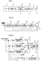
- Fig. 1 is a block diagram of a servo motor control system of a machine tool or the like controlled by CNC (computer numerical control) to which the method of the present invention is supplied.
- CNC 1 performs the program-based distribution of movement commands to a servo motor 5, which constitutes a synchronous motor that drives the various axes of a machine, and this distributed movement command is written to shared memory 2.
- a digital servo circuit 3 which controls the servo motor, is constituted from a processor (CPU), ROM, RAM, and non-volatile memory (RAM), and performs servo control in accordance with software.
- the digital servo circuit 3 processor performs position and velocity loop control using a movement command written to shared memory 2, and the servo motor rotational position and velocity, which are fed back from an encoder 6 that detects a rotor position of a motor, which will be described hereinbelow, and also performs current loop control based on a feedback current, so that the processor performs servo control and drives and controls via a power amplifier 4 the servo motor 5, which is constituted from a synchronous motor.
- Fig. 2 is a functional block diagram in which the above-mentioned digital servo circuit 3 executes the digital servo software to be executed each prescribed sampling period.
- a position controller 10 determines the deviation of a position by subtracting an encoder 6-supplied position feedback movement quantity from a movement command sent from a CNC 1 via a shared memory 2, and also outputs a velocity command by multiplying this position deviation by a position loop gain.
- a velocity controller 20 determines velocity deviation by subtracting an encoder (sensor) 6-supplied velocity feedback signal from the velocity command outputted from this position controller 10, and then, using this velocity deviation, carries out proportional/integral control, and outputs a torque command.
- a current controller 30 performs current loop processing based on the torque command outputted from the velocity controller, the actual current, which is detected and provided as feedback by a current detector, and also the servo motor 5 rotor position detected by the encoder 6, determines the servo motor U-, V-, and W-phase voltage commands, and outputs these determined voltage commands to a power amplifier 4 constituting an inverter and so forth.
- a current for each phase of the servo motor 5 is determined based on the above-mentioned voltage commands, and supplied to each phase.
- Fig. 3 is a functional block diagram of the processing, which the above-mentioned current controller 30 executed in the past.
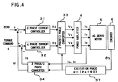
- Fig. 4 is a functional block diagram of a conventional current controller 30, which performs current control by carrying out d-q conversion.
- the current controller 30 in a servo control system which uses a synchronous motor as a servo motor, as shown in Fig. 3 and Fig. 4, determines the voltage commands Vu, Vv and Vw to each servo motor excitation phase based on an excitation phase ⁇ , which adds 90 degrees to the phase ⁇ s of a rotor position detected by an encoder or other such sensor 6.
- an excitation phase reference of an exciting current supplied to the stator, and the rotor position detected by the encoder must constitute a prescribed physical relationship.
- a is a constant
- ⁇ represents a vector product.
- the size of this torque is
- ⁇ is the angle formed by the current vector I and the flux vector ⁇ , and the angle between the excitation phase and the rotor magnetic pole position.
- the present invention provides a method, which detects the rotor position relative to the stator excitation phase reference by only moving the rotor slightly.
- the size of the torque T thereof is
- direct current is supplied to the 180-degree stator excitation phase, and the direction of rotation of the rotor is detected. If it rotates in the forward direction, the rotor magnetic pole position (position of magnetic flux ⁇ ) falls within the range from 180 to 360 degrees of the stator excitation phase, and conversely, if the rotor rotates in the reverse direction, the rotor magnetic pole position falls within the range from 0 to 180 degrees.
- a direct current is similarly supplied to an intermediate excitation phase within the range (either from 180 to 360 degree, or from 0 to 180 degree) where a rotor magnetic pole position is included, the direction of rotation of the rotor is detected, and the range where the rotor magnetic pole position is included is detected. Thereafter, these steps are repeated, making the range where the rotor magnetic pole position is included smaller successively, so that the rotor magnetic pole position is finally detected.
- a rotor magnetic pole position was at the 350-degree stator excitation phase.
- the rotor magnetic pole position is determined to be in the range from 270 to 360 degrees.
- ⁇ 35, and the direction of rotation constitutes the forward direction.
- ⁇ 12.5, and the rotor rotates in the forward direction.
- the range in which the rotor magnetic pole position is determined to exist in this manner is steadily made narrower by performing range determinations either predetermined number of times or until the rotor stops rotating so that the rotor magnetic pole position is determined.
- Fig. 5 and Fig. 6 are flowcharts of magnetic pole position detection processing executed by the processor of the digital servo circuit 3 of this embodiment.
- the digital servo circuit 3 processor commences the processing of Fig. 5 and Fig. 6.
- the processor sets an initial value of "0" in the register that stores the estimated pole position ⁇ , sets "0” as the initial rotor movement quantity in the register that stores rotor movement quantity ⁇ , and sets a value Ir, which is set as the initial exciting current, in the register that stores the direct current I for excitation (Steps S1-S3).
- Step S4 The value of the current value register, which stores the position (rotor position) of the servo motor (synchronous motor) 5 based on a signal from the encoder 6, is cleared to "0" (Step S4), and a trial counter n, which totals the number of repetitions of processing of Step S6-Step S20 that will be described hereinbelow, is set to "1" (Step S5).
- Step S6 a determination is made as to whether or not the value of the trial counter exceeds a set number of repetitions N (Step S6), and when it does not exceed this set number, 360 degrees is divided by 2 n , and a phase quantity ⁇ , 1/2 of the phase width of an estimated rotor magnetic pole position range, is determined.
- the rotor magnetic pole position is estimated to be within the entire range of 0 to 360 electrical angle, and because the trial counter n is set to "1," it is determined that a phase quantity ⁇ , which is 1/2 of the phase width of an estimated range, is 180 degrees (Step S7).
- Step S9 A determination is made as to whether or not the rotor is stopped (Step S9). This determination is made based on whether or not a feedback pulse was outputted from the encoder 6. And if the rotor is stopped, the direct current exciting current I (set value Ir at the start) stored in a register is supplied to the excitation phase ⁇ determined in Step S8, and, in addition, a timer is started (Step S10).
- Fig. 7 is a functional block diagram of current control, which controls a current by performing d-q conversion in the digital servo circuit in this rotor magnetic pole position detection processing.
- a direct current electrical current I stored in a register as a torque command is commanded, and the excitation phase ⁇ determined in Step S8 is commanded as the excitation phase. Because the rest is the same as the conventional processing shown in Fig. 4, an explanation will be omitted.
- Step S 13 a determination is made as to whether or not the rotor moved. This determination is made based on whether or not a feedback pulse was outputted from the encoder. And if it is determined that the rotor moved, the exciting current is stopped, and the timer is stopped (Steps S11, S12). And the direction of rotation of the rotor is determined, and the range where the rotor magnetic pole position is included is determined (Step S 13).
- Step S13 in a case in which it is determined that the rotor rotated in the reverse direction, the rotor magnetic pole position is in the range of 0 degrees - 180 degrees, and at this time, the "0 degrees" starting point of the range of 0 degrees - 180 degrees in which the rotor magnetic pole position is estimated to be is stored as it is without updating the estimated magnetic pole position ⁇ .
- Step S10 the rotor is started by supplying a direct current electric current -I with a reverse polarity to the excitation phase ⁇ excited in Step S10, and by setting the timer to the elapsed time measured in Step S12 (Step S15). And then, when the timer time is up (Step S16), the exciting current stops (Step S17). That is, by supplying an exciting current that is of the same size but of a reverse polarity for the same amount of time, the rotor is moved in the reverse direction the extent that it moved, thus returning the rotor to its original position.
- Step S18 the value of the current position register is read out, and this value is stored in a register as the quantity of rotor movement ⁇ (Step S18).
- the trial counter n is incremented by "1" (Step S19), and the size of the direct current electrical current I for subsequent excitation is determined by carrying out the operation of formula (3) below (Step S20).
- I Ir X (1 + n/N)
- the phase where a direct current electrical current I is supplied and the rotor magnetic pole position are caused to steadily approach each other so as to correspond. That is, both the flux vector and the current vector are caused to draw closer to each other so as to form a match. Consequently, as shown in formula (1) and formula (2) mentioned hereinabove, the torque that rotates the rotor gradually diminishes if a direct current value I is held constant. Therefore, this embodiment is constituted such that the exciting direct current value I increases each time the phase for exciting the direct current electrical current changes (approaches the rotor magnetic pole position).
- processing returns to Step S6, and processing from Step S6 to Step S20 is repeatedly executed until the trial counter n exceeds the set value N.
- the rotor magnetic pole position is in the range from 0 to 180 degrees, and 0 degrees is stored as the estimated magnetic pole position ⁇ .
- a phase quantity ⁇ 90 degrees of 1/2 of the estimated range width is added thereto to make 90 degrees, and "90 degrees + ⁇ ", in which the rotor movement quantity ⁇ is added to 90 degrees, constitutes the excitation phase of this time.
- Step S21 processing advances to Step S21, and the final estimated magnetic pole position ⁇ is determined by adding the amount of rotor movement ⁇ to an estimated magnetic pole position ⁇ . And then, the current position register is cleared, and the rotor is rotated in the reverse direction until a one rotation position signal is detected (Steps S22, S23). When a one rotation position signal is detected, the rotation of the rotor is stopped, and the movement quantity ⁇ is read from the current position register (Step S24).
- Fig. 9A and Fig. 9B are schematic diagrams of the processing of this Step S22-Step S24.
- the rotor magnetic pole position (flux position) ⁇ is determined in the stator excitation phase in the processing up to Step S21. That is, it is found that the rotor magnetic pole position is at a phase position ⁇ with respect to the excitation phase reference of the stator (electrical angle "0").
- the origin of the encoder that is, the point on the encoder mounted to the stator side for detecting the rotor position, and the one rotation signal position of the encoder mounted to the rotor side deviate by ⁇ in the forward direction.
- the encoder 6 detects a movement quantity together with its sign, the above-mentioned error can be determined by only adding this movement quantity to the estimated magnetic pole position ⁇ .
- Fig. 9C is a schematic diagram of processing for determining an excitation phase in an ordinary motor drive.
- ⁇ s was detected by the encoder 6, by adding the above-mentioned correction quantity ⁇ amr stored in memory to this detected value ⁇ s, a rotor magnetic pole position relative to a stator excitation reference ( ⁇ s + ⁇ amr) is determined, and ( ⁇ s + ⁇ amr + 90 ), obtained by adding 90 degrees to this rotor magnetic pole position, is determined as the excitation phase ⁇ .
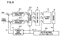
- Fig. 8 is a functional block diagram of a case in which current is controlled by performing d-q conversion using a correction quantity ⁇ amr determined according to the present invention.
- the difference between this Fig. 8 and the prior art example shown in Fig. 4 lies solely in the fact that the excitation phase ⁇ constitutes ( ⁇ s + ⁇ amr + 90 ). Since the rest of the processing is the same as the processing of Fig. 4, an explanation thereof will be omitted.
- an incremental-type encoder 6 is used as the sensor for detecting the position of the rotor, but if an absolute value detector is utilized, since a position ⁇ is detected by an absolute position detector when the magnetic pole position ⁇ is determined in Step S21, a value ( ⁇ - ⁇ ), obtained by subtracting this detected position ⁇ from the magnetic pole position ⁇ determined in Step S21, can be stored as a correction quantity ⁇ amr.
- the present invention is such that a rotor magnetic pole position is detected as much as possible without moving the rotor, and consequently, in the above-mentioned embodiment, the rotor is moved only slightly.
- the present invention can also be constituted such that a torque sensor is mounted to a synchronous motor, the direction of the torque generated when a direct current is supplied to a prescribed excitation phase is detected (in this case, the rotor need not be rotated), and a rotor magnetic pole position is detected by the direction of the torque thereof.
- Step S6 through Step S20 processing is executed until the trial counter n exceeds a set number N
- the present invention can also be constituted such that a repetition number N is not set, and processing is executed until the rotor stops rotating even when a direct current electrical current is supplied to a determined stator excitation phase. That is, in a case in which the rotor does not rotate in Step S11 (or a case in which torque is not generated), at that time, the excitation phase ⁇ determined in Step S8 constitutes the estimated magnetic pole position ⁇ .
- the above-mentioned embodiment is constituted such that ⁇ amr determined as a correction quantity is stored in non-volatile memory, but it is not always necessary to store this correction quantity in non-volatile memory.
- the correction quantity is not stored in non-volatile memory, when the system using this synchronous motor is powered ON, and the processing shown in Fig. 5 and Fig. 6 is executed, the correction quantity ⁇ amr determined in Step S26 can be stored in RAM instead of non-volatile memory.
Landscapes
- Engineering & Computer Science (AREA)
- Power Engineering (AREA)
- Control Of Motors That Do Not Use Commutators (AREA)
- Motor And Converter Starters (AREA)
- Control Of Ac Motors In General (AREA)
Abstract
Description
Claims (6)
- A method for detecting a rotor magnetic pole position in a synchronous motor, wherein said synchronous motor comprises a rotor in which magnetic poles are arranged, a stator in which exciting windings are provided and a sensor for detecting the position of this rotor,said method, which repeats a series of steps from (a) to (d), comprising the steps of:(a) supplying an electrical current to a prescribed excitation phase of said stator;(b) obtaining the direction of movement of said rotor by the application of said electrical current;(c) estimating a rotor magnetic pole position on the basis of an obtained direction of movement; and(d) specifying a prescribed excitation phase for supplying a subsequent electrical current based on an estimated magnetic pole position of said rotor.
- The method for detecting a rotor magnetic pole position in a synchronous motor according to claim 1, further comprising the step of writing into non-volatile memory the difference between a rotor magnetic pole position ultimately obtained by repeating said series of steps from (a) through (d), and a rotor position detected by said sensor at that time.
- The method for detecting a rotor magnetic pole position in a synchronous motor according to claim 1 or 2, wherein, in said Step (c), a rotor magnetic pole position is estimated based on the direction of rotor movement by virtue of a phase range, which was divided into two parts by an excitation phase to which an electrical current was supplied;in said Step (d), there is specified a prescribed excitation phase, which once again divides said phase range in which said rotor magnetic pole position is estimated to exist; anda rotor magnetic pole position is ultimately detected by steadily narrowing a phase range in which said rotor magnetic pole position is estimated to exist by repeating said series of steps from (a) through (d).
- The method for detecting a rotor magnetic pole position in a synchronous motor according to claim 1,2 or 3, wherein an electrical current of a polarity opposite the electrical current supplied in said Step (a) is supplied to a prescribed excitation phase following said Step (b).
- The method for detecting a rotor magnetic pole position in a synchronous motor according to any preceding claim, wherein an amount of movement of the rotor, which moved during detection of said rotor magnetic pole position, is added to said estimated rotor magnetic pole position as a correction quantity.
- The method for detecting a rotor magnetic pole position in a synchronous motor according to any preceding claim, wherein the value of an electrical current supplied to said prescribed excitation phase is changed at the point in time of repetition.
Applications Claiming Priority (2)
| Application Number | Priority Date | Filing Date | Title |
|---|---|---|---|
| JP25266299A JP3408468B2 (en) | 1999-09-07 | 1999-09-07 | Method for detecting rotor magnetic pole position of synchronous motor |
| JP25266299 | 1999-09-07 |
Publications (3)
| Publication Number | Publication Date |
|---|---|
| EP1085650A2 true EP1085650A2 (en) | 2001-03-21 |
| EP1085650A3 EP1085650A3 (en) | 2003-05-02 |
| EP1085650B1 EP1085650B1 (en) | 2007-02-28 |
Family
ID=17240492
Family Applications (1)
| Application Number | Title | Priority Date | Filing Date |
|---|---|---|---|
| EP00307645A Expired - Lifetime EP1085650B1 (en) | 1999-09-07 | 2000-09-05 | Method for detecting synchronous motor rotor magnetic pole position |
Country Status (4)
| Country | Link |
|---|---|
| US (1) | US6445154B1 (en) |
| EP (1) | EP1085650B1 (en) |
| JP (1) | JP3408468B2 (en) |
| DE (1) | DE60033605T2 (en) |
Cited By (7)
| Publication number | Priority date | Publication date | Assignee | Title |
|---|---|---|---|---|
| DE10116814A1 (en) * | 2001-04-04 | 2002-11-07 | Bosch Gmbh Robert | Procedure for deriving the rotor position angle |
| WO2003085817A1 (en) * | 2002-04-08 | 2003-10-16 | Dr.Johannes Heidenhain Gmbh | Method for determining the rotor position of a synchronous motor |
| WO2003043173A3 (en) * | 2001-11-16 | 2004-02-19 | Matsushita Electric Industrial Co Ltd | Motor controller |
| EP1533891A2 (en) | 2003-11-18 | 2005-05-25 | Fanuc Ltd | Position-of-magnetic-pole detecting device |
| EP1443637A3 (en) * | 2003-01-30 | 2006-05-17 | Fanuc Ltd | Controller |
| CN101821942B (en) * | 2007-10-12 | 2012-08-08 | 株式会社安川电机 | Motor control device and magnetic pole position estimation method |
| US9331618B2 (en) | 2012-12-03 | 2016-05-03 | Fanuc Corporation | Magnetic pole position detector for synchronous motor |
Families Citing this family (24)
| Publication number | Priority date | Publication date | Assignee | Title |
|---|---|---|---|---|
| JP3546817B2 (en) * | 2000-07-11 | 2004-07-28 | 日産自動車株式会社 | Magnetic pole position detection device for motor |
| DE10162380A1 (en) * | 2001-12-19 | 2003-07-03 | Bosch Gmbh Robert | Procedure for starting a brushless DC motor |
| US7002315B2 (en) * | 2002-05-28 | 2006-02-21 | Toshiba Kikai Kabushiki Kaisha | Servo control device |
| JP2004336879A (en) * | 2003-05-07 | 2004-11-25 | Tamagawa Seiki Co Ltd | Servo motor with built-in drive circuit |
| JP4631514B2 (en) * | 2005-04-07 | 2011-02-16 | パナソニック株式会社 | Magnetic pole position estimation method |
| WO2007114058A1 (en) * | 2006-03-31 | 2007-10-11 | Thk Co., Ltd. | Permanent magnet synchronization motor magnetic pole position detecting method |
| ES2362003T3 (en) * | 2006-08-14 | 2011-06-27 | Abb Schweiz Ag | PROCEDURE FOR THE DETERMINATION OF THE ANGLE POSITION OF THE ROTOR OF A ROTATING ELECTRICAL MACHINE. |
| US7622882B2 (en) * | 2006-08-21 | 2009-11-24 | Magna Electronics Inc. | Position detection device for permanent magnetic machines |
| JP2011024337A (en) * | 2009-07-15 | 2011-02-03 | Toyo Electric Mfg Co Ltd | Controller of permanent magnet synchronous motor |
| US9868183B2 (en) * | 2009-10-16 | 2018-01-16 | Weiss Gmbh | Rotary indexing table having a direct drive of the transport cam |
| JP2013138559A (en) * | 2011-12-28 | 2013-07-11 | Bosch Corp | Method and device for calibrating angle sensor attached to synchronous motor |
| JP5357300B1 (en) | 2012-05-21 | 2013-12-04 | ファナック株式会社 | Magnetic pole position detection device for detecting the magnetic pole position of a rotor in a permanent magnet synchronous motor |
| JP2014039407A (en) * | 2012-08-17 | 2014-02-27 | Okuma Corp | Magnetic pole position detection method and device for synchronous motor |
| DE102012107812A1 (en) * | 2012-08-24 | 2014-05-28 | Krones Ag | Apparatus and method for treating containers with a mechanical braking device |
| JP5661839B2 (en) | 2013-03-14 | 2015-01-28 | ファナック株式会社 | Synchronous motor control system with abnormality detection diagnosis function |
| JP5820446B2 (en) * | 2013-09-13 | 2015-11-24 | Thk株式会社 | Linear motor control device and control method |
| DE102014226967A1 (en) * | 2014-12-23 | 2016-06-23 | Thyssenkrupp Ag | A method for determining a stator current vector for starting a synchronous machine of a drive of a passenger conveyor |
| JP6191086B2 (en) * | 2015-08-04 | 2017-09-06 | Thk株式会社 | Linear actuator control device and control method |
| JP7159704B2 (en) | 2018-08-31 | 2022-10-25 | 株式会社アドヴィックス | motor controller |
| CN110081874B (en) * | 2019-03-29 | 2021-07-06 | 西人马联合测控(泉州)科技有限公司 | Vehicle positioning method and system |
| JP6739683B1 (en) * | 2019-06-06 | 2020-08-12 | 三菱電機株式会社 | Motor controller |
| JP7388087B2 (en) * | 2019-09-25 | 2023-11-29 | 富士フイルムビジネスイノベーション株式会社 | Control device and brushless motor |
| CN117240162B (en) * | 2023-11-16 | 2024-03-26 | 横川机器人(深圳)有限公司 | Method, system and medium for realizing initial phase detection of permanent magnet synchronous motor |
| CN117879429B (en) * | 2024-01-11 | 2024-07-30 | 上海铼钠克数控科技有限公司 | Rotor initial phase detection method, system, device and readable storage medium |
Family Cites Families (6)
| Publication number | Priority date | Publication date | Assignee | Title |
|---|---|---|---|---|
| EP0571076B1 (en) * | 1992-04-10 | 1996-01-17 | Matsushita Electric Industrial Co., Ltd. | Brushless DC motor |
| US5585709A (en) * | 1993-12-22 | 1996-12-17 | Wisconsin Alumni Research Foundation | Method and apparatus for transducerless position and velocity estimation in drives for AC machines |
| DE4437793C2 (en) * | 1994-10-21 | 1998-05-07 | Agie Ag Ind Elektronik | Method and device for controlling an electric motor |
| US5537020A (en) * | 1994-12-28 | 1996-07-16 | Hydro-Quebec | Method and apparatus for starting up a synchronous machine |
| JP3282657B2 (en) * | 1997-06-18 | 2002-05-20 | 株式会社安川電機 | Initial magnetic pole position estimation method for permanent magnet type brushless motor |
| US6020665A (en) * | 1998-02-25 | 2000-02-01 | Electric Boat Corporation | Permanent magnet synchronous machine with integrated magnetic bearings |
-
1999
- 1999-09-07 JP JP25266299A patent/JP3408468B2/en not_active Expired - Fee Related
-
2000
- 2000-09-05 DE DE60033605T patent/DE60033605T2/en not_active Expired - Lifetime
- 2000-09-05 EP EP00307645A patent/EP1085650B1/en not_active Expired - Lifetime
- 2000-09-06 US US09/655,876 patent/US6445154B1/en not_active Expired - Lifetime
Cited By (10)
| Publication number | Priority date | Publication date | Assignee | Title |
|---|---|---|---|---|
| DE10116814A1 (en) * | 2001-04-04 | 2002-11-07 | Bosch Gmbh Robert | Procedure for deriving the rotor position angle |
| WO2003043173A3 (en) * | 2001-11-16 | 2004-02-19 | Matsushita Electric Industrial Co Ltd | Motor controller |
| US6906494B2 (en) | 2001-11-16 | 2005-06-14 | Matsushita Electric Industrial Co., Ltd. | Motor controller |
| WO2003085817A1 (en) * | 2002-04-08 | 2003-10-16 | Dr.Johannes Heidenhain Gmbh | Method for determining the rotor position of a synchronous motor |
| US7309972B2 (en) | 2002-04-08 | 2007-12-18 | Dr. Johannes Heidenhain Gmbh | Method for determining the rotor position of a synchronous motor |
| EP1443637A3 (en) * | 2003-01-30 | 2006-05-17 | Fanuc Ltd | Controller |
| EP1533891A2 (en) | 2003-11-18 | 2005-05-25 | Fanuc Ltd | Position-of-magnetic-pole detecting device |
| EP1533891A3 (en) * | 2003-11-18 | 2007-05-16 | Fanuc Ltd | Position-of-magnetic-pole detecting device |
| CN101821942B (en) * | 2007-10-12 | 2012-08-08 | 株式会社安川电机 | Motor control device and magnetic pole position estimation method |
| US9331618B2 (en) | 2012-12-03 | 2016-05-03 | Fanuc Corporation | Magnetic pole position detector for synchronous motor |
Also Published As
| Publication number | Publication date |
|---|---|
| JP3408468B2 (en) | 2003-05-19 |
| JP2001078487A (en) | 2001-03-23 |
| EP1085650B1 (en) | 2007-02-28 |
| DE60033605D1 (en) | 2007-04-12 |
| EP1085650A3 (en) | 2003-05-02 |
| DE60033605T2 (en) | 2007-11-08 |
| US6445154B1 (en) | 2002-09-03 |
Similar Documents
| Publication | Publication Date | Title |
|---|---|---|
| EP1085650B1 (en) | Method for detecting synchronous motor rotor magnetic pole position | |
| CN101981804B (en) | Motor control device and electric power steering device | |
| EP0836270B1 (en) | Method for controlling current of ac servo motor | |
| US7671552B2 (en) | Control device | |
| US6900613B2 (en) | Motor control apparatus | |
| EP1955926A2 (en) | Control device for electric power steering apparatus | |
| US6639371B2 (en) | Method and system for controlling start of a permanent magnet machine | |
| EP2020743A2 (en) | Sensorless controlling apparatus of monitoring brushless motor | |
| US6810986B2 (en) | Electric power steering apparatus and control method therefor | |
| CN102027670A (en) | Motor control device, and electric steering device | |
| US6850026B2 (en) | Stepping motor driver | |
| JP2003070280A (en) | Motor control device | |
| KR20180120831A (en) | Apparatus and method for controlling a motor of motor driven power steering system | |
| EP2066018A2 (en) | Motor control device | |
| US20030137272A1 (en) | Stepping motor driver | |
| US6747433B2 (en) | Stepping motor controller | |
| JP2004274855A (en) | Method and device for detection and adjustment of rotor position | |
| JP2006054930A (en) | Control device for synchronous motor | |
| CN102694502A (en) | Control method and control device of motor inverter | |
| JP2006262668A (en) | Electric power steering device | |
| KR0122861B1 (en) | Drive start device and method of AC servo motor | |
| JP2764002B2 (en) | Position control system | |
| JPH07303390A (en) | Servomotor system | |
| JP2019047568A (en) | Motor controller | |
| JP7585837B2 (en) | Motor Control Device |
Legal Events
| Date | Code | Title | Description |
|---|---|---|---|
| PUAI | Public reference made under article 153(3) epc to a published international application that has entered the european phase |
Free format text: ORIGINAL CODE: 0009012 |
|
| AK | Designated contracting states |
Kind code of ref document: A2 Designated state(s): AT BE CH CY DE DK ES FI FR GB GR IE IT LI LU MC NL PT SE |
|
| AX | Request for extension of the european patent |
Free format text: AL;LT;LV;MK;RO;SI |
|
| PUAL | Search report despatched |
Free format text: ORIGINAL CODE: 0009013 |
|
| RIC1 | Information provided on ipc code assigned before grant |
Ipc: 7H 02P 6/20 A |
|
| AK | Designated contracting states |
Designated state(s): AT BE CH CY DE DK ES FI FR GB GR IE IT LI LU MC NL PT SE |
|
| AX | Request for extension of the european patent |
Extension state: AL LT LV MK RO SI |
|
| 17P | Request for examination filed |
Effective date: 20031008 |
|
| AKX | Designation fees paid |
Designated state(s): DE |
|
| RAP1 | Party data changed (applicant data changed or rights of an application transferred) |
Owner name: FANUC LTD |
|
| 17Q | First examination report despatched |
Effective date: 20050606 |
|
| GRAP | Despatch of communication of intention to grant a patent |
Free format text: ORIGINAL CODE: EPIDOSNIGR1 |
|
| GRAS | Grant fee paid |
Free format text: ORIGINAL CODE: EPIDOSNIGR3 |
|
| GRAA | (expected) grant |
Free format text: ORIGINAL CODE: 0009210 |
|
| AK | Designated contracting states |
Kind code of ref document: B1 Designated state(s): DE |
|
| REF | Corresponds to: |
Ref document number: 60033605 Country of ref document: DE Date of ref document: 20070412 Kind code of ref document: P |
|
| PLBE | No opposition filed within time limit |
Free format text: ORIGINAL CODE: 0009261 |
|
| STAA | Information on the status of an ep patent application or granted ep patent |
Free format text: STATUS: NO OPPOSITION FILED WITHIN TIME LIMIT |
|
| 26N | No opposition filed |
Effective date: 20071129 |
|
| REG | Reference to a national code |
Ref country code: DE Ref legal event code: R082 Ref document number: 60033605 Country of ref document: DE Representative=s name: HASELTINE LAKE LLP, DE |
|
| PGFP | Annual fee paid to national office [announced via postgrant information from national office to epo] |
Ref country code: DE Payment date: 20180821 Year of fee payment: 19 |
|
| REG | Reference to a national code |
Ref country code: DE Ref legal event code: R119 Ref document number: 60033605 Country of ref document: DE |
|
| PG25 | Lapsed in a contracting state [announced via postgrant information from national office to epo] |
Ref country code: DE Free format text: LAPSE BECAUSE OF NON-PAYMENT OF DUE FEES Effective date: 20200401 |