EP1085640A2 - Segmented rotor for an electric machine - Google Patents
Segmented rotor for an electric machine Download PDFInfo
- Publication number
- EP1085640A2 EP1085640A2 EP00119491A EP00119491A EP1085640A2 EP 1085640 A2 EP1085640 A2 EP 1085640A2 EP 00119491 A EP00119491 A EP 00119491A EP 00119491 A EP00119491 A EP 00119491A EP 1085640 A2 EP1085640 A2 EP 1085640A2
- Authority
- EP
- European Patent Office
- Prior art keywords
- rotor
- poles
- segment
- central axis
- segments
- Prior art date
- Legal status (The legal status is an assumption and is not a legal conclusion. Google has not performed a legal analysis and makes no representation as to the accuracy of the status listed.)
- Withdrawn
Links
- 230000004323 axial length Effects 0.000 claims description 23
- 238000003475 lamination Methods 0.000 claims description 12
- 230000005672 electromagnetic field Effects 0.000 description 9
- 238000004804 winding Methods 0.000 description 8
- 230000008901 benefit Effects 0.000 description 3
- 238000003466 welding Methods 0.000 description 3
- XEEYBQQBJWHFJM-UHFFFAOYSA-N Iron Chemical compound [Fe] XEEYBQQBJWHFJM-UHFFFAOYSA-N 0.000 description 2
- 238000006073 displacement reaction Methods 0.000 description 2
- 230000004907 flux Effects 0.000 description 2
- 239000000696 magnetic material Substances 0.000 description 2
- 230000004048 modification Effects 0.000 description 2
- 238000012986 modification Methods 0.000 description 2
- 230000007935 neutral effect Effects 0.000 description 2
- 230000004044 response Effects 0.000 description 2
- 229910052742 iron Inorganic materials 0.000 description 1
- 230000007246 mechanism Effects 0.000 description 1
- 239000002184 metal Substances 0.000 description 1
- 229910052751 metal Inorganic materials 0.000 description 1
- 238000000034 method Methods 0.000 description 1
- 229920006395 saturated elastomer Polymers 0.000 description 1
- 239000007787 solid Substances 0.000 description 1
Images


Classifications
-
- H—ELECTRICITY
- H02—GENERATION; CONVERSION OR DISTRIBUTION OF ELECTRIC POWER
- H02K—DYNAMO-ELECTRIC MACHINES
- H02K19/00—Synchronous motors or generators
- H02K19/02—Synchronous motors
- H02K19/10—Synchronous motors for multi-phase current
- H02K19/103—Motors having windings on the stator and a variable reluctance soft-iron rotor without windings
-
- Y—GENERAL TAGGING OF NEW TECHNOLOGICAL DEVELOPMENTS; GENERAL TAGGING OF CROSS-SECTIONAL TECHNOLOGIES SPANNING OVER SEVERAL SECTIONS OF THE IPC; TECHNICAL SUBJECTS COVERED BY FORMER USPC CROSS-REFERENCE ART COLLECTIONS [XRACs] AND DIGESTS
- Y10—TECHNICAL SUBJECTS COVERED BY FORMER USPC
- Y10T—TECHNICAL SUBJECTS COVERED BY FORMER US CLASSIFICATION
- Y10T29/00—Metal working
- Y10T29/49—Method of mechanical manufacture
- Y10T29/49002—Electrical device making
- Y10T29/49009—Dynamoelectric machine
- Y10T29/49012—Rotor
Definitions
- the present invention relates to an electrical machine and, more particularly, to a segmented rotor for a variable reluctance electric machine.
- variable reluctance motor utilizes a rotor formed of axially spaced apart disks that are rotatable relative to a stator portion.
- the stator portion is stationary and also formed of disks located intermediate adjacent pairs of the rotor disks.
- a stator winding circumscribes each stator pole pair and, when energized, directs an electromagnetic field axially through a magnetic circuit formed of the energized stator pole pair and adjacent rotor poles. Torque is generated when a pair of rotor poles move toward a position of axial alignment relative to an adjacent energized stator pole pair to minimize the reluctance. Examples of this type of variable reluctance motor are disclosed in U.S. Patent No. 3,700,944 to Heintz and U.S. Patent No. 3,992,641 to Heinrich et al.
- variable reluctance motor is formed of an elongated rotor mounted coaxially within an elongated annular stationary stator.
- Each of the rotor and stator has a plurality of radially protruding poles or teeth that extend axially.
- An annular air gap separates the rotor poles from the stator poles.
- the stator generates an electromagnetic field when a stator winding associated with a pair of opposed stator poles is energized. The electromagnetic field is directed radially with respect to a central axis extending longitudinally through the rotor and the stator.
- the electromagnetic field urges a pair of opposed rotor poles into radial alignment with the stator poles being energized to minimize the reluctance of the corresponding magnetic circuit formed by the energized stator poles and adjacent rotor poles.
- the movement of the rotor in turn, generates torque. Examples of this type of variable reluctance machine are disclosed in U.S. Patent No. 4,670,696 to Byrne et al. and U.S. Patent No. 5,747,912 to Sakuma et al.
- the present invention is directed to a rotor for an electric machine that includes a first elongated rotor segment having a plurality of axially extending rotor poles arranged in a circular array about a central axis that extends longitudinally through the rotor.
- a second rotor segment which engages the first rotor segment, has a plurality of axially extending rotor poles arranged in a circular array about the central axis.
- the poles of the second rotor segment are rotated in a first direction about the central axis relative to the poles of the first rotor segment.
- the rotor also includes a third rotor segment that engages at least one of the first and second rotor segments.
- the third rotor segment has a plurality of axially extending rotor poles arranged in a circular array about the central axis.
- the poles of the third rotor segment are rotated in a second direction about the central axis relative to the poles of the first rotor segment.
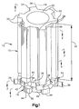
- Figs. 1-4 illustrate a rotor 10, in accordance with the present invention, formed of three axially extending rotor segments 12, 14 and 16.
- Each of the rotor segments 12, 14 and 16 circumscribes a central axis 18 extending through the rotor 10.
- each of the rotor segments 12, 14 and 16 is formed of a plurality of axially stacked laminations that are secured together, such as by welding or other known methods, to form the segmented rotor stack 10.
- the first rotor segment 12 has a plurality of axially extending rotor poles 20 arranged in a circular array about the central axis 18. Each of the poles 20 protrudes radially outwardly from a generally cylindrical core 22. Each of the poles 20 is circumferentially spaced apart from adjacent poles.
- each of the poles 20 preferably are chamfered or curved, having from about a one degree to about a three degree radial arc that extends the axial length of each pole 20.
- the chamfered pole corners 24 and 26 reduce flux linking between unaligned poles 20 of the elongated rotor segment 12 and an energized phase of a stator in which the rotor 10 is mounted. This, in turn, helps to avoid magnetic saturation that typically occurs at the corners of opposed rotor poles of a conventional rotor segment when an adjacent stator pole is energized.
- the affected pole When a rotor pole corner becomes saturated, the affected pole is less responsive to an electromagnetic field and, in turn, produces less torque for a given amount of electric current.
- the rounded corners 24 and 26 of the poles 20 inhibit such saturation from occurring and, therefore improves the torque response of a motor.
- the rotor segment 12 also has ends 28 and 30 that are axially spaced apart a length, indicated at 32.
- the axial length 32 of rotor segment 12 preferably is much greater than axial lengths 34 and 36 of the other rotor segments 14 and 16, respectively.
- the length 32 of the segment 12 may be from about 70 mm to about 90 mm, while the lengths 34, 36 of each respective segment 14, 16 ranges be from about 5 mm to about 15 mm.
- the second rotor segment 14 also includes a plurality of axially extending rotor poles 38 that protrude radially from an inner cylindrical core 39.
- the cylindrical core 39 is aligned axially with the cylindrical core 22.
- the rotor poles 38 are circumferentially spaced apart in a circular array about the central axis 18.
- the configuration of each pole 38 is substantially similar to each corresponding pole 20. However, rather than the entire pole pitch of each of the poles 38 being aligned axially with a corresponding pole 20 of the first rotor segment 12, as in a conventional rotor, the rotor segment 14, including the poles 38, is rotated about the central axis 18 relative to the first rotor segment 12.
- the center of each of the poles 38 is rotated a predetermined amount in a clockwise direction, indicated at + ⁇ in Fig. 3, relative to the center of each corresponding pole 20 of the rotor segment 12.
- + ⁇ ranges from about six degrees to about nine degrees.
- the second rotor segment 14 has spaced axially apart ends 40 and 42.
- the second rotor segment 14 also engages and is fixed relative to the first rotor segment 12.
- a lamination of the rotor segment 14 at the first end 28 axially engages a lamination of the rotor segment 12 at the second end 30.
- At least part of these axially engaging laminations are fixed together in a known manner, such as by welding, so that the angular orientation of the rotor poles 38 and 20 are fixed relative to each other.
- the third rotor segment 16 also includes a plurality of axially extending rotor poles 44 arranged in a circular array about the central axis 18.
- the poles 44 protrude radially outwardly from an inner cylindrical core 46.
- the core 46 is axially aligned with the cores 22 and 39 of the respective first and second rotor segments 12 and 14.
- the third rotor segment 16 extends axially a predetermined length, indicated at 36, between first and second ends 48 and 50. A substantial part of the first end 48 axially engages the second end 30 of the first rotor segment 12.
- a lamination of the rotor segment 16 at the first end 48 axially engages and is fixed to a lamination of the rotor segment 14 at its second end 42.
- the rotor poles 44 are dimensioned and configured to be substantially identical to the poles 38 of the second rotor segment 14.
- the rotor poles 44 are circumferentially spaced apart in a circular array about the central axis 18.
- the rotor segment 16, including the poles 44 is rotated in a counterclockwise direction about the axis 18 relative to corresponding rotor segments 12 and 14.
- a center of each pole 44 is rotated or offset a predetermined amount, indicated at - ⁇ in Fig. 4, relative to the center of a corresponding pole 20 of the first rotor segment 12.
- the angle - ⁇ for example, ranges from about six degrees to about nine degrees in a counterclockwise direction relative to rotor segment 12. This is opposite of the direction that rotor segment 14 is rotated relative to the rotor segment 12.
- the angular orientation of the rotor poles 44 is fixed relative to the rotor poles 20 and 38 of the respective first and second rotor segments 12 and 14.
- Figs. 5 and 6 schematically illustrate a variable reluctance machine or motor 54 that includes the rotor 10 in accordance with the present invention.
- the relative angular orientation of the poles 20, 38 and 44 remains fixed.
- each of the rotor segments 12, 14, 16 is secured concentrically about an elongated shaft 52 that extends axially through the rotor 10 to provide for rotation relative to a stator 56.
- the shaft 52 may be a solid rod or a hollow tube which, for example, forms part of a drive mechanism.
- the stator 56 is fixed relative to an elongated motor housing 58.
- the housing 58 encloses the stator 56 and the rotor 10, with the rotor shaft 52 being supported at adjacent ends (not shown) of the housing for rotation of the rotor 10 and rotor shaft 52 about the central axis 18.
- the stator 56 includes a generally cylindrical metal core portion 60 affixed to the housing 58.
- the stator 56 also includes a plurality of axially extending poles 62 that protrude radially inwardly from the core portion 60.
- a plurality of axially extending slots 64 are formed between each adjacent pair of stator poles 62.
- the stator poles 62 are circumferentially spaced apart in a circular array around the central axis 18.
- the stator 56 is formed of a plurality of axially stacked laminations which are secured together in a known manner.
- the stator 56 has an axial length commensurate with or greater than the axial length of the rotor 10.
- a plurality of stator phase windings 66 are disposed in the slots 64. Each winding is wound around a diametrically opposed pair of stator poles 62.
- the stator windings 66 are connected with appropriate vehicle electrical circuitry (not shown) for controlling the flow of electric current through the windings 54. This, in turn, controls the electromagnetic field provided by each stator pole pair and, in turn, the torque provided by the motor 54.
- the stator 56 shown in Figs. 5 and 6 has eight stator poles 62 which are arranged to be energized in pole pairs, indicated at 62A, 62a, 62B, 62b, 62C, 62c, 62D, and 62d.
- the letters which follow each reference number represent the four phases Aa, Bb, Cc, and Dd of the motor 54.
- Each pole pair 62A, 62a, 62B, 62b, 62C, 62c, 62D, and 62d is wound by a separate phase winding 66.
- the motor 54 is illustrated as a four-phase variable reluctance motor, the present invention is equally applicable to machines having other number of phases.
- the rotor 10 is rotatably mounted coaxially within the stator 56.
- the rotor 10 is secured to the rotor shaft 52, such as by being press-fit onto the shaft.
- the rotor 10 includes six axially extending pole portions 68 which are circumferentially spaced apart and circumscribe the central axis 18, as described above.
- the pole portions 68 are formed of the corresponding poles 20, 38 and 44.
- only part of each pole 38 and 44 of each respective rotor segment 14 and 16 is axially aligned with a corresponding pole 20 of the rotor segment 12, thereby forming each pole portion 68.
- the rotor 10 preferably is formed of a magnetic material, such as iron or another magnetic material, so that the pole portions 68 are responsive to the electromagnetic field provided by an energized pair of stator poles 62A, 62a, 62B, 62b, 62C, 62c, 62D, and 62d.
- a magnetic material such as iron or another magnetic material
- Fig. 7 is a graph illustrating torque (Nm) as a function of rotor position (mechanical degrees) for a over thirty mechanical degrees of rotor rotation.
- a first curve 70 illustrates a torque-angle curve for a conventional variable reluctance motor. The curve 70 shows a significant amount of drag associated with about the first nine degrees of mechanical movement.
- a second curve 72 shows a torque-angle curve 72 for a motor 54 having a rotor 10 configured in accordance with the present invention. In contrast to the curve 70, the curve 72 exhibits substantially symmetric torque over the entire first thirty degrees of rotor position.
- the curve 72 does not exhibit the significant drag inherent in a conventional variable reluctance motor, shown by curve 70.
- FIG. 5 and 6 there is a slight displacement between a magnetic neutral axis and the geometric neutral axis for each rotor pole portion 68.
- This displacement is more pronounced when a pole portion 68 is out of radial alignment with an energized stator pole 62A, 62a, 62B, 62b, 62C, 62c, 62D, or 62d.
- rotor segment 14 has a pair of opposed rotor poles 38 that are either partially or wholly aligned with the excited stator pole pair while the poles of the longer rotor segment 12 are out of alignment.
- the rotor segment 14 has poles 38 that are exposed to a greater amount of the electromagnetic field provided by the energized stator poles 62A and 62a.
- the increased exposure of at least part of the rotor portion 68 to the electromagnetic field facilitates movement of the rotor 10 toward a position of minimum reluctance. This, in turn, provides an increase in the amount of torque for a given amount of current, i.e., there is an increased torque-to-current gain when running up or down the torque-angle curve 72 (Fig. 7).
- each rotor pole portion 68 and adjacent stator pole 62A, 62a, 62B, 62b, 62C, 62c, 62D, and 62d achieves similar torque-angle characteristics. Additionally, because the rotor 10 has two rotor segments 14 and 16, which are shifted in opposite directions, the motor 54 is able to achieve a more symmetric torque-angle response when the motor 54 is energized to rotate the rotor in either a clockwise or counterclockwise direction.
- Fig. 8 illustrates an alternative embodiment of a rotor 100, in accordance with the present invention, formed of three coaxial rotor segments 102, 104, and 106.
- the rotor 100 is formed of an elongated rotor segment 102 mounted intermediate two shorter rotor segments 104 and 106. Each of the shorter rotor segments 104 and 106 is rotated in an opposite direction about a central axis 108 relative to the intermediate segment 102.
- the intermediate rotor segment 102 has a plurality of axially extending rotor poles 110 arranged in a circular array about the central axis 108. Each of the poles 110 protrudes radially outwardly from a generally cylindrical core 112. Each of the poles 110 is circumferentially spaced apart and extends axially the entire length of the rotor segment 102.
- the radially outer corners of each of the poles 110 preferably are chamfered or rounded, having from about a one degree to about a three degree arc. The chamfered pole corners help to reduce flux linking between the intermediate rotor segment 102 and an energized stator pole pair. This further helps to avoid magnetic saturation that tends to occur when adjacent poles of the rotor segment 102 are out of radial alignment relative to an energized stator pole.
- the second or upper rotor segment 104 also includes a plurality of axially extending rotor poles 114.
- the poles 114 protrude radially outwardly from an inner cylindrical core 116 and are arranged in a circular array about the central axis 108.
- the rotor segment 104, including the poles 114, is rotated about the central axis 108 in a counterclockwise direction relative to the corresponding poles 110 of the intermediate rotor segment 102.
- the poles 114 of rotor segment 104 are angularly shifted from about six to about nine degrees counterclockwise relative to corresponding poles 110 of the first rotor segment 102, as shown in Fig. 8.
- a lower end 118 of rotor segment 104 axially engages and is fixed to a first end 120 of the intermediate rotor segment 102, such as by welding corresponding rotor laminations in a known manner. Accordingly, the angular orientation of each array of rotor poles 110 and 114 are fixed relative to each other.
- the third or lower rotor segment 106 also has a plurality of axially extending rotor poles 122 arranged in a circular array about the central axis 108.
- the rotor poles 122 are circumferentially spaced apart and are rotated in a clockwise direction about the axis 108 relative to corresponding poles 110, 114 of the other rotor segments 102, 104.
- the third segment 116 including its poles 122, is rotated from about six to about nine degrees in a clockwise direction relative to the first rotor segment 102.
- the third rotor segment 106 extends axially a predetermined length between first and second ends 124 and 126.
- the first end 124 of the third rotor segment 106 axially engages and is fixed to a second or lower end 128 of the elongated intermediate rotor segment 102.
- the angular orientation of the rotor poles 122 is fixed relative to the rotor poles 110 and 114 of the respective first and second rotor segments 102 and 104.
- a portion of the each corresponding rotor pole 110, 114, and 122 preferably remains axially aligned, as illustrated in Fig. 8.
- the relative dimensions and angular orientation of the respective rotor segments 102, 104, and 106 are substantially identical to that described with respect to the embodiment of Figs. 1-4.
- an electric machine having a segmented rotor stack in accordance with the present invention, provides a more symmetric torque-angle curve.
- the relatively shorter segments that are shifted relative to the longer segment further result in a motor having improved torque-to-current gain.
- the invention relates to a rotor for an electric machine comprising: a first elongated rotor segment having a plurality of axially extending rotor poles arranged in a circular array about a central axis that extends longitudinally through said rotor; and a second rotor segment engaging said first rotor segment, said second rotor segment having a plurality of axially extending rotor poles arranged in a circular array about the central axis, said poles of said second rotor segment being rotated in a first direction about the central axis relative to corresponding poles of said first rotor segment, said poles of said second rotor segment being of equal number to said poles of said first rotor segment.
Landscapes
- Engineering & Computer Science (AREA)
- Power Engineering (AREA)
- Iron Core Of Rotating Electric Machines (AREA)
- Synchronous Machinery (AREA)
Abstract
Description
- The present invention relates to an electrical machine and, more particularly, to a segmented rotor for a variable reluctance electric machine.
- One type of variable reluctance motor utilizes a rotor formed of axially spaced apart disks that are rotatable relative to a stator portion. The stator portion is stationary and also formed of disks located intermediate adjacent pairs of the rotor disks. A stator winding circumscribes each stator pole pair and, when energized, directs an electromagnetic field axially through a magnetic circuit formed of the energized stator pole pair and adjacent rotor poles. Torque is generated when a pair of rotor poles move toward a position of axial alignment relative to an adjacent energized stator pole pair to minimize the reluctance. Examples of this type of variable reluctance motor are disclosed in U.S. Patent No. 3,700,944 to Heintz and U.S. Patent No. 3,992,641 to Heinrich et al.
- Another type of variable reluctance motor is formed of an elongated rotor mounted coaxially within an elongated annular stationary stator. Each of the rotor and stator has a plurality of radially protruding poles or teeth that extend axially. An annular air gap separates the rotor poles from the stator poles. The stator generates an electromagnetic field when a stator winding associated with a pair of opposed stator poles is energized. The electromagnetic field is directed radially with respect to a central axis extending longitudinally through the rotor and the stator. The electromagnetic field urges a pair of opposed rotor poles into radial alignment with the stator poles being energized to minimize the reluctance of the corresponding magnetic circuit formed by the energized stator poles and adjacent rotor poles. The movement of the rotor, in turn, generates torque. Examples of this type of variable reluctance machine are disclosed in U.S. Patent No. 4,670,696 to Byrne et al. and U.S. Patent No. 5,747,912 to Sakuma et al.
- The present invention is directed to a rotor for an electric machine that includes a first elongated rotor segment having a plurality of axially extending rotor poles arranged in a circular array about a central axis that extends longitudinally through the rotor. A second rotor segment, which engages the first rotor segment, has a plurality of axially extending rotor poles arranged in a circular array about the central axis. The poles of the second rotor segment are rotated in a first direction about the central axis relative to the poles of the first rotor segment. The rotor also includes a third rotor segment that engages at least one of the first and second rotor segments. The third rotor segment has a plurality of axially extending rotor poles arranged in a circular array about the central axis. The poles of the third rotor segment are rotated in a second direction about the central axis relative to the poles of the first rotor segment.
- The foregoing and other features and advantages of the invention will become more apparent to one skilled in the art upon consideration of the following description of the invention and the accompanying drawings in which:
- Fig. 1 is an isometric view of a first embodiment of a rotor in accordance with the present invention;
- Fig. 2 is a top elevation of a first part of the rotor of Fig. 1 taken along line 2-2;
- Fig. 3 is a top elevation of a second part of the rotor of Fig. 1 taken along line 3-3;
- Fig. 4 is a top elevation of a third part of the rotor of Fig. 1 taken along line 4-4;
- Fig. 5 is a sectional view of an electric machine in accordance with the present invention;
- Fig. 6 is a side sectional view of the electric machine of Fig. 5 taken along line 6-6;
- Fig. 7 is a graph illustrating torque versus rotor position for the machine of Fig. 5; and
- Fig. 8 is an isometric view of another embodiment of a rotor in accordance with the present invention.
-
- Figs. 1-4 illustrate a
rotor 10, in accordance with the present invention, formed of three axially extendingrotor segments rotor segments central axis 18 extending through therotor 10. Preferably, each of therotor segments rotor stack 10. - The
first rotor segment 12 has a plurality of axially extendingrotor poles 20 arranged in a circular array about thecentral axis 18. Each of thepoles 20 protrudes radially outwardly from a generallycylindrical core 22. Each of thepoles 20 is circumferentially spaced apart from adjacent poles. - In addition, the radially
outer corners poles 20 preferably are chamfered or curved, having from about a one degree to about a three degree radial arc that extends the axial length of eachpole 20. Thechamfered pole corners unaligned poles 20 of theelongated rotor segment 12 and an energized phase of a stator in which therotor 10 is mounted. This, in turn, helps to avoid magnetic saturation that typically occurs at the corners of opposed rotor poles of a conventional rotor segment when an adjacent stator pole is energized. When a rotor pole corner becomes saturated, the affected pole is less responsive to an electromagnetic field and, in turn, produces less torque for a given amount of electric current. Therounded corners poles 20 inhibit such saturation from occurring and, therefore improves the torque response of a motor. - The
rotor segment 12 also hasends axial length 32 ofrotor segment 12 preferably is much greater thanaxial lengths other rotor segments length 32 of thesegment 12 may be from about 70 mm to about 90 mm, while thelengths respective segment - The
second rotor segment 14 also includes a plurality of axially extendingrotor poles 38 that protrude radially from an innercylindrical core 39. Thecylindrical core 39 is aligned axially with thecylindrical core 22. Therotor poles 38 are circumferentially spaced apart in a circular array about thecentral axis 18. The configuration of eachpole 38 is substantially similar to eachcorresponding pole 20. However, rather than the entire pole pitch of each of thepoles 38 being aligned axially with acorresponding pole 20 of thefirst rotor segment 12, as in a conventional rotor, therotor segment 14, including thepoles 38, is rotated about thecentral axis 18 relative to thefirst rotor segment 12. Preferably, the center of each of thepoles 38 is rotated a predetermined amount in a clockwise direction, indicated at + in Fig. 3, relative to the center of eachcorresponding pole 20 of therotor segment 12. For example, + ranges from about six degrees to about nine degrees. - The
second rotor segment 14 has spaced axially apart ends 40 and 42. Thesecond rotor segment 14 also engages and is fixed relative to thefirst rotor segment 12. In particular, a lamination of therotor segment 14 at thefirst end 28 axially engages a lamination of therotor segment 12 at thesecond end 30. At least part of these axially engaging laminations are fixed together in a known manner, such as by welding, so that the angular orientation of therotor poles - The
third rotor segment 16 also includes a plurality of axially extendingrotor poles 44 arranged in a circular array about thecentral axis 18. Thepoles 44 protrude radially outwardly from an innercylindrical core 46. Thecore 46 is axially aligned with thecores second rotor segments third rotor segment 16 extends axially a predetermined length, indicated at 36, between first andsecond ends first end 48 axially engages thesecond end 30 of thefirst rotor segment 12. Specifically, a lamination of therotor segment 16 at thefirst end 48 axially engages and is fixed to a lamination of therotor segment 14 at itssecond end 42. - The
rotor poles 44 are dimensioned and configured to be substantially identical to thepoles 38 of thesecond rotor segment 14. Therotor poles 44 are circumferentially spaced apart in a circular array about thecentral axis 18. Therotor segment 16, including thepoles 44, is rotated in a counterclockwise direction about theaxis 18 relative tocorresponding rotor segments pole 44 is rotated or offset a predetermined amount, indicated at - in Fig. 4, relative to the center of acorresponding pole 20 of thefirst rotor segment 12. The angle -, for example, ranges from about six degrees to about nine degrees in a counterclockwise direction relative torotor segment 12. This is opposite of the direction thatrotor segment 14 is rotated relative to therotor segment 12. The angular orientation of therotor poles 44 is fixed relative to therotor poles second rotor segments - Figs. 5 and 6 schematically illustrate a variable reluctance machine or
motor 54 that includes therotor 10 in accordance with the present invention. The relative angular orientation of thepoles rotor segments elongated shaft 52 that extends axially through therotor 10 to provide for rotation relative to astator 56. Theshaft 52 may be a solid rod or a hollow tube which, for example, forms part of a drive mechanism. - The
stator 56 is fixed relative to anelongated motor housing 58. Thehousing 58 encloses thestator 56 and therotor 10, with therotor shaft 52 being supported at adjacent ends (not shown) of the housing for rotation of therotor 10 androtor shaft 52 about thecentral axis 18. - The
stator 56 includes a generally cylindricalmetal core portion 60 affixed to thehousing 58. Thestator 56 also includes a plurality of axially extending poles 62 that protrude radially inwardly from thecore portion 60. A plurality of axially extendingslots 64 are formed between each adjacent pair of stator poles 62. The stator poles 62 are circumferentially spaced apart in a circular array around thecentral axis 18. Preferably, thestator 56 is formed of a plurality of axially stacked laminations which are secured together in a known manner. Thestator 56 has an axial length commensurate with or greater than the axial length of therotor 10. - A plurality of
stator phase windings 66 are disposed in theslots 64. Each winding is wound around a diametrically opposed pair of stator poles 62. Thestator windings 66 are connected with appropriate vehicle electrical circuitry (not shown) for controlling the flow of electric current through thewindings 54. This, in turn, controls the electromagnetic field provided by each stator pole pair and, in turn, the torque provided by themotor 54. - The
stator 56 shown in Figs. 5 and 6 has eight stator poles 62 which are arranged to be energized in pole pairs, indicated at 62A, 62a, 62B, 62b, 62C, 62c, 62D, and 62d. The letters which follow each reference number represent the four phases Aa, Bb, Cc, and Dd of themotor 54. Eachpole pair motor 54 is illustrated as a four-phase variable reluctance motor, the present invention is equally applicable to machines having other number of phases. - The
rotor 10 is rotatably mounted coaxially within thestator 56. Therotor 10 is secured to therotor shaft 52, such as by being press-fit onto the shaft. Therotor 10 includes six axially extendingpole portions 68 which are circumferentially spaced apart and circumscribe thecentral axis 18, as described above. Thepole portions 68 are formed of the correspondingpoles pole respective rotor segment corresponding pole 20 of therotor segment 12, thereby forming eachpole portion 68. - The
rotor 10 preferably is formed of a magnetic material, such as iron or another magnetic material, so that thepole portions 68 are responsive to the electromagnetic field provided by an energized pair ofstator poles - Fig. 7 is a graph illustrating torque (Nm) as a function of rotor position (mechanical degrees) for a over thirty mechanical degrees of rotor rotation. A
first curve 70 illustrates a torque-angle curve for a conventional variable reluctance motor. Thecurve 70 shows a significant amount of drag associated with about the first nine degrees of mechanical movement. Asecond curve 72 shows a torque-angle curve 72 for amotor 54 having arotor 10 configured in accordance with the present invention. In contrast to thecurve 70, thecurve 72 exhibits substantially symmetric torque over the entire first thirty degrees of rotor position. Advantageously, thecurve 72 does not exhibit the significant drag inherent in a conventional variable reluctance motor, shown bycurve 70. - Referring to Figs. 5 and 6, there is a slight displacement between a magnetic neutral axis and the geometric neutral axis for each
rotor pole portion 68. This displacement is more pronounced when apole portion 68 is out of radial alignment with an energizedstator pole stator pole pair rotor segment 14 has a pair ofopposed rotor poles 38 that are either partially or wholly aligned with the excited stator pole pair while the poles of thelonger rotor segment 12 are out of alignment. Accordingly, therotor segment 14 haspoles 38 that are exposed to a greater amount of the electromagnetic field provided by the energizedstator poles rotor portion 68 to the electromagnetic field facilitates movement of therotor 10 toward a position of minimum reluctance. This, in turn, provides an increase in the amount of torque for a given amount of current, i.e., there is an increased torque-to-current gain when running up or down the torque-angle curve 72 (Fig. 7). - While the benefits have been described with respect to a single
rotor pole portion 68 and energizedstator pole pair rotor pole portion 68 andadjacent stator pole rotor 10 has tworotor segments motor 54 is able to achieve a more symmetric torque-angle response when themotor 54 is energized to rotate the rotor in either a clockwise or counterclockwise direction. - Fig. 8 illustrates an alternative embodiment of a
rotor 100, in accordance with the present invention, formed of threecoaxial rotor segments rotor 100 is formed of anelongated rotor segment 102 mounted intermediate twoshorter rotor segments shorter rotor segments central axis 108 relative to theintermediate segment 102. - The
intermediate rotor segment 102 has a plurality of axially extendingrotor poles 110 arranged in a circular array about thecentral axis 108. Each of thepoles 110 protrudes radially outwardly from a generallycylindrical core 112. Each of thepoles 110 is circumferentially spaced apart and extends axially the entire length of therotor segment 102. The radially outer corners of each of thepoles 110 preferably are chamfered or rounded, having from about a one degree to about a three degree arc. The chamfered pole corners help to reduce flux linking between theintermediate rotor segment 102 and an energized stator pole pair. This further helps to avoid magnetic saturation that tends to occur when adjacent poles of therotor segment 102 are out of radial alignment relative to an energized stator pole. - The second or
upper rotor segment 104 also includes a plurality of axially extendingrotor poles 114. Thepoles 114 protrude radially outwardly from an innercylindrical core 116 and are arranged in a circular array about thecentral axis 108. Therotor segment 104, including thepoles 114, is rotated about thecentral axis 108 in a counterclockwise direction relative to the correspondingpoles 110 of theintermediate rotor segment 102. Preferably, thepoles 114 ofrotor segment 104 are angularly shifted from about six to about nine degrees counterclockwise relative tocorresponding poles 110 of thefirst rotor segment 102, as shown in Fig. 8. - A
lower end 118 ofrotor segment 104 axially engages and is fixed to afirst end 120 of theintermediate rotor segment 102, such as by welding corresponding rotor laminations in a known manner. Accordingly, the angular orientation of each array ofrotor poles - The third or
lower rotor segment 106 also has a plurality of axially extendingrotor poles 122 arranged in a circular array about thecentral axis 108. Therotor poles 122 are circumferentially spaced apart and are rotated in a clockwise direction about theaxis 108 relative tocorresponding poles other rotor segments third segment 116, including itspoles 122, is rotated from about six to about nine degrees in a clockwise direction relative to thefirst rotor segment 102. - The
third rotor segment 106 extends axially a predetermined length between first and second ends 124 and 126. Thefirst end 124 of thethird rotor segment 106 axially engages and is fixed to a second orlower end 128 of the elongatedintermediate rotor segment 102. The angular orientation of therotor poles 122 is fixed relative to therotor poles second rotor segments corresponding rotor pole respective rotor segments - Advantageously, an electric machine having a segmented rotor stack, in accordance with the present invention, provides a more symmetric torque-angle curve. The relatively shorter segments that are shifted relative to the longer segment further result in a motor having improved torque-to-current gain.
- From the above description of the invention, those skilled in the art will perceive improvements, changes and modifications. For example, when an electric machine having a different number of phases and/or rotor poles is provided, different amounts of relative rotation between rotor segments may be required to achieve a desired symmetric torque-angle curve. Such improvements, changes and modifications within the skill of the art are intended to be covered by the appended claims.
- According to its broadest aspect the invention relates to a rotor for an electric machine comprising: a first elongated rotor segment having a plurality of axially extending rotor poles arranged in a circular array about a central axis that extends longitudinally through said rotor; and a second rotor segment engaging said first rotor segment, said second rotor segment having a plurality of axially extending rotor poles arranged in a circular array about the central axis, said poles of said second rotor segment being rotated in a first direction about the central axis relative to corresponding poles of said first rotor segment, said poles of said second rotor segment being of equal number to said poles of said first rotor segment.
- It should be noted that the objects and advantages of the invention may be attained by means of any compatible combination(s) particularly pointed out in the items of the following summary of the invention.
-
- 1. A rotor for an electric machine comprising:
- a first elongated rotor segment having a plurality of axially extending rotor poles arranged in a circular array about a central axis that extends longitudinally through said rotor;
- a second rotor segment engaging said first rotor segment, said second rotor segment having a plurality of axially extending rotor poles arranged in a circular array about the central axis, said poles of said second rotor segment being rotated in a first direction about the central axis relative to corresponding poles of said first rotor segment, said poles of said second rotor segment being of equal number to said poles of said first rotor segment; and
- a third rotor segment engaging at least one of said first and second rotor segments, said third rotor segment having a plurality of axially extending rotor poles arranged in a circular array about the central axis, said poles of said third rotor segment being rotated in a second direction about the central axis relative to corresponding poles of said first rotor segment, said poles of said third rotor segment being equal in number to said poles of said first and second rotor segments.
- 2. A rotor wherein each of said poles of said second and third rotor segments is rotated a predetermined amount about the central axis relative to said poles of said first rotor segment.
- 3. A rotor wherein the predetermined amount ranges from about 6 degrees to about 9 degrees.
- 4. A rotor wherein each of said rotor segments is formed of a plurality of axially secured laminations.
- 5. A rotor wherein said first rotor segment has a first axial length and said second and third rotor segments have axial lengths which are less than the first axial length.
- 6. A rotor wherein said second and third rotor segments have substantially equal axial lengths.
- 7. A rotor wherein a part of each pole of said second and third rotor segments is axially aligned with part of a corresponding pole of said first rotor segment.
- 8. An electric machine comprising:
- an elongated rotor shaft having a central axis extending longitudinally through said shaft;
- an elongated rotor attached coaxially about said shaft, said rotor being formed of three axially extending rotor segments, a first of said rotor segments axially engaging a second of said rotor segments and a third of the rotor segments axially engaging one of said second and first rotor segments, each of said rotor segments having an equal plurality of spaced apart rotor poles arranged in a circular array about the central axis, the rotor poles of said second and third rotor segments being rotated about the central axis relative to corresponding rotor poles of the first rotor segment; and
- a stator having a plurality of stator poles arranged in circular array about the central axis and concentrically about said rotor, said rotor being rotatable relative to said stator, each of said stator poles extending axially a length commensurate with the axial length of said rotor.
- 9. An electric machine wherein said poles of said second and third rotor segments are rotated in opposite directions about the central axis relative to corresponding poles of said first rotor segment.
- 10. An electric machine wherein a part of each pole of said second and third rotor segments is axially aligned with a corresponding pole of said first rotor segment.
- 11. An electric machine wherein said poles of said second and third rotor segments are rotated about the central axis a predetermined angle from about 6 degrees to about 9 degrees relative to corresponding poles of said first rotor segment.
- 12. An electric machine wherein each rotor segment is formed of a plurality of axially stacked laminations fixed to said rotor shaft.
- 13. An electric machine wherein said first rotor segment has a first axial length and said second and third rotor segments have respective axial lengths which are less than the first axial length.
- 14. An electric machine wherein said second and third rotor segments have substantially equal axial lengths.
-
Claims (10)
- A rotor for an electric machine comprising:a first elongated rotor segment having a plurality of axially extending rotor poles arranged in a circular array about a central axis that extends longitudinally through said rotor;a second rotor segment engaging said first rotor segment, said second rotor segment having a plurality of axially extending rotor poles arranged in a circular array about the central axis, said poles of said second rotor segment being rotated in a first direction about the central axis relative to corresponding poles of said first rotor segment, said poles of said second rotor segment being of equal number to said poles of said first rotor segment; anda third rotor segment engaging at least one of said first and second rotor segments, said third rotor segment having a plurality of axially extending rotor poles arranged in a circular array about the central axis, said poles of said third rotor segment being rotated in a second direction about the central axis relative to corresponding poles of said first rotor segment, said poles of said third rotor segment being equal in number to said poles of said first and second rotor segments.
- A rotor as set forth in claim 1 wherein each of said poles of said second and third rotor segments is rotated a predetermined amount about the central axis relative to said poles of said first rotor segment.
- A rotor as set forth in claim 2 wherein the predetermined amount ranges from about 6 degrees to about 9 degrees.
- A rotor as set forth in claim 1 wherein each of said rotor segments is formed of a plurality of axially secured laminations.
- A rotor as set forth in claim 1 wherein said first rotor segment has a first axial length and said second and third rotor segments have axial lengths which are less than the first axial length.
- A rotor as set forth in claim 5 wherein said second and third rotor segments have substantially equal axial lengths,
and/ or wherein a part of each pole of said second and third rotor segments is axially aligned with part of a corresponding pole of said first rotor segment. - An electric machine comprising:an elongated rotor shaft having a central axis extending longitudinally through said shaft;an elongated rotor attached coaxially about said shaft, said rotor being formed of three axially extending rotor segments, a first of said rotor segments axially engaging a second of said rotor segments and a third of the rotor segments axially engaging one of said second and first rotor segments, each of said rotor segments having an equal plurality of spaced apart rotor poles arranged in a circular array about the central axis, the rotor poles of said second and third rotor segments being rotated about the central axis relative to corresponding rotor poles of the first rotor segment; anda stator having a plurality of stator poles arranged in circular array about the central axis and concentrically about said rotor, said rotor being rotatable relative to said stator, each of said stator poles extending axially a length commensurate with the axial length of said rotor.
- An electric machine as set forth in any of the preceding claims wherein said poles of said second and third rotor segments are rotated in opposite directions about the central axis relative to corresponding poles of said first rotor segment.
and/ or wherein a part of each pole of said second and third rotor segments is axially aligned with a corresponding pole of said first rotor segment.
and/ or wherein said poles of said second and third rotor segments are rotated about the central axis a predetermined angle from about 6 degrees to about 9 degrees relative to corresponding poles of said first rotor segment. - An electric machine as set forth in any of the preceding claims wherein each rotor segment is formed of a plurality of axially stacked laminations fixed to said rotor shaft.
and/ or wherein said first rotor segment has a first axial length and said second and third rotor segments have respective axial lengths which are less than the first axial length.
and/ or wherein said second and third rotor segments have substantially equal axial lengths. - A rotor for an electric machine comprising:a first elongated rotor segment having a plurality of axially extending rotor poles arranged in a circular array about a central axis that extends longitudinally through said rotor; anda second rotor segment engaging said first rotor segment, said second rotor segment having a plurality of axially extending rotor poles arranged in a circular array about the central axis, said poles of said second rotor segment being rotated in a first direction about the central axis relative to corresponding poles of said first rotor segment, said poles of said second rotor segment being of equal number to said poles of said first rotor segment.
Applications Claiming Priority (2)
| Application Number | Priority Date | Filing Date | Title |
|---|---|---|---|
| US399267 | 1995-03-06 | ||
| US09/399,267 US6198194B1 (en) | 1999-09-17 | 1999-09-17 | Segmented rotor for an electric machine |
Publications (2)
| Publication Number | Publication Date |
|---|---|
| EP1085640A2 true EP1085640A2 (en) | 2001-03-21 |
| EP1085640A3 EP1085640A3 (en) | 2004-01-07 |
Family
ID=23578880
Family Applications (1)
| Application Number | Title | Priority Date | Filing Date |
|---|---|---|---|
| EP00119491A Withdrawn EP1085640A3 (en) | 1999-09-17 | 2000-09-18 | Segmented rotor for an electric machine |
Country Status (4)
| Country | Link |
|---|---|
| US (1) | US6198194B1 (en) |
| EP (1) | EP1085640A3 (en) |
| JP (1) | JP3459230B2 (en) |
| BR (1) | BR0004217A (en) |
Families Citing this family (9)
| Publication number | Priority date | Publication date | Assignee | Title |
|---|---|---|---|---|
| JP3804343B2 (en) * | 1999-06-29 | 2006-08-02 | 松下電器産業株式会社 | Motor core and motor using the same |
| US6504285B2 (en) * | 2001-02-08 | 2003-01-07 | Jae Shin Yun | Vector motor |
| US6809456B2 (en) * | 2001-02-08 | 2004-10-26 | Jae Shin Yun | Vector motor |
| US6864616B2 (en) | 2001-10-09 | 2005-03-08 | General Electric Company | Method and apparatus for forming an electric motor having stacked laminations |
| US20090302808A1 (en) * | 2008-06-05 | 2009-12-10 | Viral Nandkumar Patel | Flywheel electricity generator |
| WO2013151891A1 (en) * | 2012-04-03 | 2013-10-10 | Russel Marvin | Permanent magnet machine with tab pole rotor |
| US9407115B2 (en) | 2012-04-03 | 2016-08-02 | Lcdrives Corp. | Shaft attachment means for high efficiency permanent magnet machine with separated tab pole rotor |
| JP2015171181A (en) * | 2014-03-05 | 2015-09-28 | 株式会社ミツバ | Switched reluctance motor |
| US10404108B2 (en) * | 2014-06-20 | 2019-09-03 | Regal Beloit America, Inc. | System and methods of electric machine rotor position detection |
Citations (2)
| Publication number | Priority date | Publication date | Assignee | Title |
|---|---|---|---|---|
| US4616151A (en) | 1984-12-07 | 1986-10-07 | General Motors Corporation | Armature with quiet core construction |
| US5969454A (en) | 1995-10-19 | 1999-10-19 | Tridelta Industries, Inc. | Switched reluctance motor |
Family Cites Families (20)
| Publication number | Priority date | Publication date | Assignee | Title |
|---|---|---|---|---|
| FR82903E (en) * | 1962-02-05 | 1964-05-08 | Improvements made to electric machines of the variable reluctance type | |
| DE1638401B2 (en) * | 1967-07-13 | 1973-01-25 | Licentia Patent-Verwaltungs-Gmbh, 6000 Frankfurt | RELUCTANT MOTOR DESIGNED FOR ONLY ONE SYNCHRONOUS SPEED |
| US3700944A (en) | 1971-11-08 | 1972-10-24 | Ford Motor Co | Disc-type variable reluctance rotating machine |
| GB1488161A (en) * | 1974-01-22 | 1977-10-05 | Cav Ltd | Variable reluctance electric motor |
| US3992641A (en) | 1974-11-22 | 1976-11-16 | Westinghouse Electric Corporation | Polyphase disc reluctance motor |
| US4626719A (en) * | 1980-07-22 | 1986-12-02 | Warner Electric Brake & Clutch Company | Stepping motor having rotor with axially spaced sections |
| JPS6039336A (en) | 1983-08-12 | 1985-03-01 | Nippon Denso Co Ltd | Cooling structure of flat type rotary electric machine |
| EP0180815B2 (en) | 1984-10-19 | 1994-12-28 | Kollmorgen Corporation | Variable speed variable reluctance electrical machines |
| JPS62103577A (en) | 1985-10-31 | 1987-05-14 | Canon Inc | frequency generator |
| US4920292A (en) * | 1986-08-29 | 1990-04-24 | Papst-Motoren Gmbh & Co. Kg | Motor having rotor capable of both stepped rotary and axial shift motions |
| US4959578A (en) | 1987-11-24 | 1990-09-25 | Axial Electric, Inc. | Dual rotor axial air gap induction motor |
| US5245238A (en) | 1991-04-30 | 1993-09-14 | Sundstrand Corporation | Axial gap dual permanent magnet generator |
| US5485046A (en) * | 1992-02-20 | 1996-01-16 | Dana Corporation | Variable reluctance electric motor |
| WO2004075379A1 (en) | 1992-03-18 | 2004-09-02 | Kazuto Sakai | Axial gap rotaitng electric machine |
| US5679995A (en) * | 1992-08-12 | 1997-10-21 | Seiko Epson Corporation | Permanent magnet rotor of brushless motor |
| DE4301076A1 (en) | 1993-01-16 | 1994-07-21 | Forschungszentrum Juelich Gmbh | Magnetic bearing cell with rotor and stator |
| US5763976A (en) | 1993-12-15 | 1998-06-09 | Parker-Hannifin Corp. | Stator wound resolver with staggered rotor |
| JP3446350B2 (en) | 1994-11-29 | 2003-09-16 | アイシン精機株式会社 | Switched reluctance motor |
| US5739612A (en) * | 1996-09-03 | 1998-04-14 | Davenport; Norban Earl | Auxiliary power source |
| FR2758018B1 (en) | 1996-12-31 | 2006-06-16 | Valeo Electronique | ELECTRIC MACHINE OF SYNCHRONOUS TYPE |
-
1999
- 1999-09-17 US US09/399,267 patent/US6198194B1/en not_active Expired - Lifetime
-
2000
- 2000-09-12 JP JP2000276871A patent/JP3459230B2/en not_active Expired - Fee Related
- 2000-09-15 BR BR0004217-0A patent/BR0004217A/en not_active IP Right Cessation
- 2000-09-18 EP EP00119491A patent/EP1085640A3/en not_active Withdrawn
Patent Citations (2)
| Publication number | Priority date | Publication date | Assignee | Title |
|---|---|---|---|---|
| US4616151A (en) | 1984-12-07 | 1986-10-07 | General Motors Corporation | Armature with quiet core construction |
| US5969454A (en) | 1995-10-19 | 1999-10-19 | Tridelta Industries, Inc. | Switched reluctance motor |
Also Published As
| Publication number | Publication date |
|---|---|
| JP2001103720A (en) | 2001-04-13 |
| EP1085640A3 (en) | 2004-01-07 |
| US6198194B1 (en) | 2001-03-06 |
| JP3459230B2 (en) | 2003-10-20 |
| BR0004217A (en) | 2001-04-10 |
Similar Documents
| Publication | Publication Date | Title |
|---|---|---|
| US4841186A (en) | Electronically commutated, collectorless directed-current motor | |
| EP0544310B1 (en) | Permanent magnet type dynamoelectric machine rotor | |
| US5041749A (en) | High speed, high power, single phase brushless DC motor | |
| JP2594813B2 (en) | Variable reluctance motor | |
| US4998032A (en) | Permanent magnet excited electric motor | |
| US4583015A (en) | Single-phase brushless motor with multisector stator armature poles having different cross-sections | |
| EP0813287B1 (en) | Switched reluctance motors | |
| US4823037A (en) | DC Electric motor having field poles of permanent magnet | |
| CN102904400A (en) | Transverse Switched Reluctance Motor | |
| US6057621A (en) | Cylindrical radial gap type motor structure | |
| TWI414130B (en) | Single-phase brushless motor | |
| US5744893A (en) | Brushless motor stator design | |
| EP1155948B1 (en) | Bicycle hub dynamo and bicycle | |
| JPWO2019058643A1 (en) | Insulator and stator and motor equipped with it | |
| US6198194B1 (en) | Segmented rotor for an electric machine | |
| US4591766A (en) | Brushless direct current motor | |
| IE56810B1 (en) | Brushless dc motor | |
| EP0468763B1 (en) | Permanent magnet type stepping motor | |
| US5089737A (en) | Dc rotary electric machine of permanent magnet field type | |
| US20040155545A1 (en) | Switched reluctance motor having improved stator pole design | |
| US7679256B2 (en) | Rotary electric machine | |
| CN112789785A (en) | Claw-pole motor with annular coils and meandering coils | |
| US6424070B1 (en) | Magnetically centering torque motor | |
| JP2001119874A (en) | Rotating electric machine stator | |
| JP2002078260A (en) | Permanent magnet motor |
Legal Events
| Date | Code | Title | Description |
|---|---|---|---|
| PUAI | Public reference made under article 153(3) epc to a published international application that has entered the european phase |
Free format text: ORIGINAL CODE: 0009012 |
|
| AK | Designated contracting states |
Kind code of ref document: A2 Designated state(s): AT BE CH CY DE DK ES FI FR GB GR IE IT LI LU MC NL PT SE |
|
| AX | Request for extension of the european patent |
Free format text: AL;LT;LV;MK;RO;SI |
|
| TPAD | Observations filed by third parties |
Free format text: ORIGINAL CODE: EPIDOS TIPA |
|
| PUAL | Search report despatched |
Free format text: ORIGINAL CODE: 0009013 |
|
| AK | Designated contracting states |
Kind code of ref document: A3 Designated state(s): AT BE CH CY DE DK ES FI FR GB GR IE IT LI LU MC NL PT SE |
|
| AX | Request for extension of the european patent |
Extension state: AL LT LV MK RO SI |
|
| RIC1 | Information provided on ipc code assigned before grant |
Ipc: 7H 02K 19/10 B Ipc: 7H 02K 1/24 A |
|
| RAP1 | Party data changed (applicant data changed or rights of an application transferred) |
Owner name: TRW AUTOMOTIVE U.S. LLC |
|
| 17P | Request for examination filed |
Effective date: 20040524 |
|
| AKX | Designation fees paid |
Designated state(s): DE FR GB IT |
|
| 17Q | First examination report despatched |
Effective date: 20071108 |
|
| STAA | Information on the status of an ep patent application or granted ep patent |
Free format text: STATUS: THE APPLICATION HAS BEEN WITHDRAWN |
|
| 18W | Application withdrawn |
Effective date: 20101025 |