EP1085542A2 - Rotary electric switch and contact therefore - Google Patents
Rotary electric switch and contact therefore Download PDFInfo
- Publication number
- EP1085542A2 EP1085542A2 EP00307501A EP00307501A EP1085542A2 EP 1085542 A2 EP1085542 A2 EP 1085542A2 EP 00307501 A EP00307501 A EP 00307501A EP 00307501 A EP00307501 A EP 00307501A EP 1085542 A2 EP1085542 A2 EP 1085542A2
- Authority
- EP
- European Patent Office
- Prior art keywords
- contacts
- contact
- end portions
- electric switch
- movable
- Prior art date
- Legal status (The legal status is an assumption and is not a legal conclusion. Google has not performed a legal analysis and makes no representation as to the accuracy of the status listed.)
- Granted
Links
- 239000000463 material Substances 0.000 claims description 15
- 230000008878 coupling Effects 0.000 claims description 2
- 238000010168 coupling process Methods 0.000 claims description 2
- 238000005859 coupling reaction Methods 0.000 claims description 2
- 230000000875 corresponding effect Effects 0.000 description 11
- 230000003466 anti-cipated effect Effects 0.000 description 4
- 229920003376 Stanyl® TW241F10 Polymers 0.000 description 3
- 238000013461 design Methods 0.000 description 3
- 230000007246 mechanism Effects 0.000 description 3
- 238000000926 separation method Methods 0.000 description 3
- 239000013598 vector Substances 0.000 description 3
- RYGMFSIKBFXOCR-UHFFFAOYSA-N Copper Chemical compound [Cu] RYGMFSIKBFXOCR-UHFFFAOYSA-N 0.000 description 2
- 229910052802 copper Inorganic materials 0.000 description 2
- 239000010949 copper Substances 0.000 description 2
- 230000000694 effects Effects 0.000 description 2
- 229920003189 Nylon 4,6 Polymers 0.000 description 1
- BQCADISMDOOEFD-UHFFFAOYSA-N Silver Chemical compound [Ag] BQCADISMDOOEFD-UHFFFAOYSA-N 0.000 description 1
- XAGFODPZIPBFFR-UHFFFAOYSA-N aluminium Chemical compound [Al] XAGFODPZIPBFFR-UHFFFAOYSA-N 0.000 description 1
- 229910052782 aluminium Inorganic materials 0.000 description 1
- 238000013459 approach Methods 0.000 description 1
- 238000004891 communication Methods 0.000 description 1
- 239000004020 conductor Substances 0.000 description 1
- 230000002596 correlated effect Effects 0.000 description 1
- 230000005520 electrodynamics Effects 0.000 description 1
- 238000009413 insulation Methods 0.000 description 1
- 230000003993 interaction Effects 0.000 description 1
- 238000000034 method Methods 0.000 description 1
- 238000012986 modification Methods 0.000 description 1
- 230000004048 modification Effects 0.000 description 1
- 230000005405 multipole Effects 0.000 description 1
- 238000005192 partition Methods 0.000 description 1
- 229920000642 polymer Polymers 0.000 description 1
- 230000008569 process Effects 0.000 description 1
- 229910052709 silver Inorganic materials 0.000 description 1
- 239000004332 silver Substances 0.000 description 1
- 229920003002 synthetic resin Polymers 0.000 description 1
- 239000000057 synthetic resin Substances 0.000 description 1
Images




Classifications
-
- H—ELECTRICITY
- H01—ELECTRIC ELEMENTS
- H01H—ELECTRIC SWITCHES; RELAYS; SELECTORS; EMERGENCY PROTECTIVE DEVICES
- H01H1/00—Contacts
- H01H1/12—Contacts characterised by the manner in which co-operating contacts engage
- H01H1/36—Contacts characterised by the manner in which co-operating contacts engage by sliding
- H01H1/365—Bridging contacts
-
- H—ELECTRICITY
- H01—ELECTRIC ELEMENTS
- H01H—ELECTRIC SWITCHES; RELAYS; SELECTORS; EMERGENCY PROTECTIVE DEVICES
- H01H1/00—Contacts
- H01H1/12—Contacts characterised by the manner in which co-operating contacts engage
- H01H1/14—Contacts characterised by the manner in which co-operating contacts engage by abutting
- H01H1/20—Bridging contacts
- H01H1/2041—Rotating bridge
-
- H—ELECTRICITY
- H01—ELECTRIC ELEMENTS
- H01H—ELECTRIC SWITCHES; RELAYS; SELECTORS; EMERGENCY PROTECTIVE DEVICES
- H01H9/00—Details of switching devices, not covered by groups H01H1/00 - H01H7/00
- H01H9/30—Means for extinguishing or preventing arc between current-carrying parts
- H01H9/40—Multiple main contacts for the purpose of dividing the current through, or potential drop along, the arc
-
- H—ELECTRICITY
- H01—ELECTRIC ELEMENTS
- H01H—ELECTRIC SWITCHES; RELAYS; SELECTORS; EMERGENCY PROTECTIVE DEVICES
- H01H9/00—Details of switching devices, not covered by groups H01H1/00 - H01H7/00
- H01H9/10—Adaptation for built-in fuses
Definitions
- the invention relates to an electric switch and more particularly to a four-break electric switch having two pairs of rotatably movable contacts and four fixed contacts and a contact suitable for use in such a switch.
- switches having ratings of up to several hundred amps are well known.
- Some such switches include an integral fuse element.
- the load contact, i.e. fixed contact, in such a switch is selectively engaged and disengaged by a movable blade, i.e. movable contact, that is cantilever supported in spaced relation to the fixed contact.
- a movable blade i.e. movable contact
- the contacts and the space in which the movable contacts move must be relatively large.
- mount movable contacts to rotate about a central portion thereof to accomplish two breaks with two fixed contacts (one break at each end of the movable contact) in about the same space as one break is accomplished in the cantilever type of contact mounting.
- break refers to a location at which movable contacts can be selectively placed in contact with a fixed contact or other movable contacts to "make” or “break” current.
- break increases the effective contact area, i.e. the area in which the fixed contact touches the moving contact and thus increases switching capacity.
- U.S. patent 3,632,935 is representative of patents disclosing a two-break contact rotatable about a center thereof.
- the entire current carrying area of a pair of movable contacts generates a force of attraction therebetween that can be used to overcome the force of repulsion to thereby avoid "popping", i.e. separation of the contacts due to EMF which results in damage to the contacts and failure of the switch.
- pairs of contacts that are rotatable about a central portion in rotary switches having more than two breaks.
- the "S" Type Fused Combination Switches” sold by MEM SANTON SWITCHGEAR implements a four break rotary switch in a relatively small package by using four single knife contacts on a rotating member and fixed U shaped contacts having two extending portions on respective sides of the knife contacts disposed around the rotating member.
- the relatively small dimensions of the extending portions are not adequate to generate the high attractive forces necessary to avoid popping at high currents.
- the size and configuration of the fixed contacts does not permit the extending portions to be easily flexed towards each other and thus even if a high force of attraction was generated, the contacts would not "grip" the movable contact and thus are not as stable as true contact pairs. Extending the size of the fixed contacts would increase the size of the device.
- a first aspect of the invention is an electric switch comprisinghousing, four contacts mounted to the housing, a rotary member rotatably mounted with respect to the housing, and two pairs of movable contacts.
- Each movable contact has a central portion coupled to the rotary member and end portions adapted to contact a corresponding one of the contacts.
- the pairs of movable contacts are mounted in substantially the same plane.
- a second aspect of the invention is an electric switch comprising a housing, four contacts mounted to the housing, a rotary member rotatably mounted with respect to the housing, and two pairs of movable contacts.
- Each movable contact has a central portion coupled to the rotary member and end portions adapted to contact a corresponding one of the contacts.
- a longitudinal axis of the end portions extend at an angle with respect to a longitudinal axis of the central portion and the end portions are in substantially the same plane as the central portion.
- a third aspect of the invention is a movable contact for an electric switch of the type having fixed contacts, a rotary member, and at least one pair of the movable contacts mounted on the rotary member.
- the movable contacts each comprises a central portion adapted to be coupled to the rotary member and end portions adapted to define breaks with a corresponding one of the fixed contacts.
- a longitudinal axis of the end portions extend at an angle with respect to a longitudinal axis of the central portion and the end portions are in substantially the same plane as the central portion.
- switch 10 includes housing 20, preferably made of a synthetic resin material or other electrically insulated material, removable cover 40, and rotatable handle 46.
- housing 20 substantially surrounds the other components disclosed below.
- housing 20 can take any form in which the other components are mounted thereto.
- housing 20 can be in the form of a base plate.
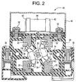
- two fixed contacts 22 and two fixed contacts 23 are fixedly disposed in housing 20.
- Fixed contacts 22 and 23 of the preferred embodiment are essentially plate-like members and lie in substantially the same plane as described in greater detail below.
- a rotary member comprises shaft 28 coupled to handle 46 and contact holder 26 made of a material that has electric and thermal insulation properties as described in greater detail below.
- Two pairs of movable contacts 100 are mounted in contact holder 26 to rotate in the directions indicated by double-headed arrow A about an axis of shaft 28 when shaft 28 is rotated by rotating handle 46.
- each end portion 102 begins to contact fixed contacts 22 and 23 at the same time during rotation of handle 46. Also, it can be seen that switch 100 defines four breaks corresponding to each of four pairs of end portions 102.
- One fixed contact 22 and one fixed contact 23 are electrically coupled to terminals 32 to which fuse clips 42 are electrically coupled. Accordingly, fuse element 44, such as a standard fast acting or slow blow thermal fuse, can be connected between two fixed contacts 22 and 23.
- Cover 40 serves to isolate and protect fuse element 44 and is optional.
- fuse element 44 can be exposed or fuse element 44 can be omitted and terminals 32 can be electrically coupled in a direct manner to provide an unfused switch.
- the other fixed contacts 22 and, 23 are electrically coupled to terminals 30 to which incoming (line) and outgoing (load) can be connected in a known manner.
- the line and load terminals are interchangeable in the preferred embodiment.
- One set of movable contacts 100 and fixed contacts 22 and 23, i.e. two pairs of movable contacts 100, two fixed contacts 22, and two fixed contacts 23, are illustrated in Fig. 2.
- the invention can include plural sets of fixed contacts 22 and 23 and plural sets of movable contacts 100 mounted on a single shaft 28.
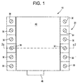
- the preferred embodiment has six such sets as indicated in Fig. 1 by six sets of load terminals 30.
- movable contacts 100 are supported in contact carrier 26 as two opposing pairs of parallel contacts 100 extending through respective openings in contact carrier 26.
- Springs 24, in the form of a leaf spring in the preferred embodiment, are disposed in contact carrier 26, as illustrated, to press movable contacts 100 into a seat defined in carrier 26 and towards an opposing movable contact 100.
- Figs 5, 6, and 7 illustrate one of moving contacts 100 in detail.
- Each moving contact 100 includes two end portions 102, having longitudinal axis a, and a central portion 104, having longitudinal axis b.
- the angle ⁇ between axis a and axis b is preferably in the range of 30°- 50° inclusive, more preferably in the range of 35°-45°, and is 37° in the preferred embodiment.
- This angle defined between end portions 102 and central portion 104 permits contacts 100 to be placed in contact carrier 26 with the pairs of movable contacts 100 in substantially the same plane P and with end portions 102 in different quadrants of housing 20 while avoiding crossing of movable contacts 100 as illustrated in Figs. 2 and 3.
- the separation of end portions 102 of a pair of movable contacts 100 pair with respect to end portions 102 of the other of movable contacts 100 pair afforded by the angled end portions 102 permits an adequate stroke of movement by end portions 102 with respect to fixed contacts 22 and 23. Also, it can be seen that this configuration reduces the radial dimension of the space required by movable contacts 100 while still providing a relatively long movable contact to create the requisite attractive force as described in detail below.
- each movable contact 100 has contact projection 106 formed on respective end portions 102.
- end portions 102 have tapered edges 108 defined thereon (see Fig. 3 also) defining sacrificial material which serves the purpose of providing material to burn off during arcing caused by current breaking.
- the geometry of the current path achieved by groove 60 in fixed contacts 22/23 described below pushes the seat of the arc to tapered edges 108. This way the main contact area does not burn up.
- This configuration facilitates making and breaking electrical contact with fixed contacts 22/23 in the manner described below. Note that tapered edges 108 do not touch fixed contacts 22/23.
- Figs. 8 and 9 illustrate one of fixed contacts 22 in detail
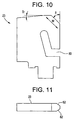
- Figs. 10 and 11 illustrate one of fixed contacts 23 in detail
- the primary difference between fixed contacts 22 and fixed contacts 23 is the shape and orientations of groove 60 formed therein.
- the different groove shape in fixed contacts 22/23 ensures that the geometry of the current path at all 4 breaks is similar.
- the groove 60 is generated to get a "Bend-Back" effect, because the arc generated while breaking is pushed away from the point of break thereby minimizing the roughness caused by arcing at the point of the break (which is also the point of engagement at the time of making). This allows easy movement of movable contacts 100 during further engagement.
- Other aspects of fixed contacts 22 and 23 are similar and thus these elements will be discussed together with reference to Figs. 8-11 in which similar elements are labeled with like reference numerals.
- Each fixed contact 22/23 is a substantially rectangular plate-like member having a corner removed to define a width w along which contact projection 106 moves as contact carrier 26 is rotated.
- Angle ⁇ preferably is about 40°-50° inclusive and is about 47° in the preferred embodiment.
- An edge of fixed contact 22/23 is chamfered to define sloped receiving surfaces 62 on either side of the edge of fixed contact 22/23 to facilitate making and breaking with movable contacts 100 as described below.
- the chamfered edge defines angle ⁇ (see Fig. 9) that is preferably less than 10°, 4° in the preferred embodiment.
- end portions 102 travel through about 45° when moving from “off” to “on” or vice versa, within the quadrants defined by partitions 34 of housing 20.
- a dwell mechanism can be incorporated in switch 10 to quickly move movable contacts 100 over and off of fixed contacts 22 and 23. In other words, once movable contacts 100 pass a dwell point, a large spring force or the like can be used to accelerate movable contacts 100.
- the angle of end portions 102 with respect to central portions 104 of movable contacts 100 overcomes many of the obstacles to the design of a four-break rotary contact switch. However, this angled configuration also raises other design considerations that must be overcome.
- the above-noted attractive and repulsive EMF act in a direction that is perpendicular to the direction of current flow through the contacts.
- the attractive force due to central portions 104 can be represented as vector Fa1 at the center of central portions 104 directed into the page in Fig. 5.
- the attractive force due to end portions 102 can be represented as vectors Fa2 at the center of end portions 102 directed into the page in Fig. 5.
- Fa2 is offset from the longitudinal axis of central portion 104 and thus will cause a moment, i.e. a torque, tending to twist or rotate movable contacts 100 in contact carrier 26 as illustrated by arrows b in Fig. 4.
- the repulsive force Fr acts at the point of contact between movable contacts 100 and fixed contacts 22/23 and thus can be represented as vectors Fr at the center of contact projections 106 directed out of the page in Fig. 5. It can be seen that Fr is offset from the longitudinal axis of central portion 104 and thus will cause a moment, i.e. a torque, tending to twist or rotate movable contacts 100 in contact carrier 26 as illustrated by arrows c in Fig. 4. Accordingly, the forces acting on movable contacts 100 are complex and the relative sizes and angles of movable contacts 100 must be designed to account for these forces to avoid popping of the contacts and damage to the switch.
- Table 2 below illustrates Examples 1-19 of the various variables and forces which must be balanced to avoid failure of switch 10.
- Table 1 lists the symbol, units, description and value of the various dimensions of an example of movable contact 100 with symbols correlated to Figs. 5 and 7. Symbol Unit Description Value N No No.
- Table 2 shows the results of the calculation of the various forces on the contacts for various levels of instantaneous current.
- Symbol I Fa1 Fa2 Ma Ms Fr Mr Ma+Ms Units KA N N N-m N-m N N-m N-mm Ex. 1 4 0.54 0.21 3.15 89.25 2.23 26.75 92.40 Ex. 2 4.5 0.68 0.27 3.98 89.25 2.76 33.14 93.23 Ex. 3 5 0.85 0.33 4.92 89.25 3.34 40.12 94.17 Ex. 4 5.5 1.02 0.40 5.95 89.25 3.97 47.68 95.20 Ex. 5 6 1.22 0.48 7.08 89.25 4.65 55.81 96.33 Ex.
- the switch having contacts of the listed dimensions can withstand instantaneous currents of up to almost 8.5kA which corresponds to accepted ratings for a 63A switch.
- the dimensions can be varied to achieve other desired current ratings without contact popping as long as the equation is satisfied.
- the attractive forces overcome the repulsive forces, they will offer resistance to moving contacts 100 sliding over the fixed contacts 22/23, if this passage of high current happens at the time the switch is in the process of being moved to the ON position. This resistance should therefore be overcome by the mechanism that drives the contacts.
- Fixed contacts 22/23 and movable contacts 100 can be made of any appropriate electrically conductive material.
- copper, silver plated copper, aluminum or the like can be used.
- contact carrier 26 must be made of a temperature and pressure resistant material.
- Applicant has found that the material sold under the number TW241F10 and trade name Stanyl by DSM Polymers International is suitable for contact carrier 26.
- This material has a heat distortion temperature at 1.8 MPa (HDT A) of >290° C.
- this material has a peak temperature (1 minute) per UL 746 B of >250° C. Applicant has found that use of this material yields a contact carrier that does not distort despite the moments applied to movable contacts 100.
- the shape and dimensions of the contacts can be varied based on the mechanical dimensional, and electrical requirements of the switch.
- Plural sets of movable contact pairs can be mounted on a single shaft to provide a switch of higher capacity or to provide a multi-pole device.
- Plural sets can also be configured by connections in series or parallel to offer different ratings of current or voltage.
- the contact pairs or sets can be in the form of modules that can be easily added or removed from the switch. Switches with higher current ratings and lower switching duties can be constructed by using two breaks in parallel instead of four breaks in series.
- the switch can be fused or non-fused.
- the movable contacts can be movably mounted in the switch through any appropriate mechanism.
Landscapes
- Rotary Switch, Piano Key Switch, And Lever Switch (AREA)
Abstract
Description
| Symbol | Unit | Description | Value |
| N | No | No. of moving | 2 |
| I1 | M | Length of central portion | 14.8 |
| I2 | Mm | Length of end portion (derived) | 5.78 |
| x | Mm | Distance between Center points of contact projections | 24 |
| y | Mm | Center of bent portion from edge (derived) | 4.25 |
| z | Mm | Distance of center points from edge | 6 |
| k | Mm | Width of the moving contact | 5 |
| Ar | Cm2 | Cross sectional area at contact zone | 0.11 |
| a | Mm | Separation between moving contacts in a pair | 3 |
| t | Mm | Thickness of moving contact | 1.6 |
| w | Mm | Width of fixed | 11 |
| Fa | N | Electrodynamic Force of Attraction | |
| Fa1 | N | Attraction force due to length x of movable contact | |
| Fa2 | N | Attraction force due to length y of movable contact | |
| Fr | N | Repulsions force at contact points | |
| Fs | N | Spring force on each movable contact | 10.5 |
| Mr | N-mm | Moment of Fr about edge of movable contact | |
| Ma | N-mm | Moment of Fa about edge of movable contact | |
| Ms | N-mm | Moment of Fs about edge of movable contact |
| Symbol | I | Fa1 | Fa2 | Ma | Ms | Fr | Mr | Ma+Ms |
| Units | KA | N | N | N-m | N-m | N | N-m | N-mm |
| Ex. 1 | 4 | 0.54 | 0.21 | 3.15 | 89.25 | 2.23 | 26.75 | 92.40 |
| Ex. 2 | 4.5 | 0.68 | 0.27 | 3.98 | 89.25 | 2.76 | 33.14 | 93.23 |
| Ex. 3 | 5 | 0.85 | 0.33 | 4.92 | 89.25 | 3.34 | 40.12 | 94.17 |
| Ex. 4 | 5.5 | 1.02 | 0.40 | 5.95 | 89.25 | 3.97 | 47.68 | 95.20 |
| Ex. 5 | 6 | 1.22 | 0.48 | 7.08 | 89.25 | 4.65 | 55.81 | 96.33 |
| Ex. 6 | 6.5 | 1.43 | 0.56 | 8.31 | 89.25 | 5.37 | 64.48 | 97.56 |
| Ex. 7 | 7 | 1.66 | 0.65 | 9.64 | 89.25 | 6.14 | 73.69 | 98.89 |
| Ex. 8 | 7.5 | 1.90 | 0.74 | 11.07 | 89.25 | 6.95 | 83.43 | 100.32 |
| Ex. 9 | 8 | 2.16 | 0.84 | 12.59 | 89.25 | 7.81 | 93.69 | 101.84 |
| Ex. 10 | 8.5 | 2.44 | 0.95 | 14.21 | 89.25 | 8.70 | 104.45 | 103.46 |
| Ex. 11 | 9 | 2.74 | 1.07 | 15.93 | 89.25 | 9.64 | 115.71 | 105.18 |
| Ex. 12 | 9.5 | 3.05 | 1.19 | 17.75 | 89.25 | 10.62 | 127.46 | 107.00 |
| Ex. 13 | 10 | 3.38 | 1.32 | 19.67 | 89.25 | 11.64 | 139.70 | 108.92 |
| Ex. 14 | 10.5 | 3.73 | 1.46 | 21.69 | 89.25 | 12.70 | 152.40 | 110.94 |
| Ex. 15 | 11 | 4.09 | 1.60 | 23.80 | 89.25 | 13.80 | 165.57 | 113.05 |
| Ex. 16 | 11.5 | 4.47 | 1.75 | 26.20 | 89.25 | 14.93 | 179.20 | 115.27 |
| Ex. 17 | 12 | 4.87 | 1.90 | 28.33 | 89.25 | 16.11 | 193.29 | 117.58 |
| Ex. 18 | 12.5 | 5.28 | 2.06 | 30.74 | 89.25 | 17.32 | 207.82 | 119.99 |
| Ex. 19 | 13 | 5.71 | 2.23 | 33.25 | 89.25 | 18.57 | 222.78 | 122.50 |
Claims (10)
- An electric switch (10) comprising:a housing (20);four contacts (22, 23) mounted to said housing (20);a rotary member (26, 28) rotatably mounted with respect to said housing (20); andtwo pairs of movable contacts (100), each movable contact (100) having a central portion (104) coupled to said rotary member (26, 28) and having end portions (102) adapted to contact a corresponding one of said contacts (22, 23), said pairs of movable contact s (100) being mounted in substantially the same plane.
- An electric switch (10) as recited in claim 1, wherein said contacts (22, 23) are fixed with respect to said housing (20).
- An electric switch (10) as recited in claim 2, wherein a longitudinal axis of each of said end portions (102) defines an angle with respect to a longitudinal axis of said central portion (104).
- An electric switch (10) comprising:a housing (20);four contacts (22, 23) mounted to said housing (20); anda rotary member (26, 28) rotatably mounted with respect to said housing (20); andtwo pairs of movable contact (100)s (100), each movable contact (100) having a central portion (104) coupled to said rotary member (26, 28) and having end portions (102) adapted to contact a corresponding one of said contacts (22, 23), a longitudinal axis of said end portions (102) extending at an angle with respect to a longitudinal axis of said central portion (104) and said end portions (102) being in substantially the same plane as said central portion (104).
- An electric switch (10) as recited in claim 4, wherein said contacts (22, 23) are fixed with respect to said housing (20).
- An electric switch (10) as recited in claim 5, wherein said rotary member (26, 28) comprises a shaft (28) and a contact carrier (26) mounted on said shaft (28), said center portions being supported by said contact carrier (26) and said end portions (102) extending away from said contact carrier (26).
- A movable contact (100) for an electric switch (10) of the type having fixed contacts (22, 23), a rotary member (26, 28), and at least one pair of the movable contact (100)s (100) mounted on the rotary member (26, 28) said movable contact (100)s (100) each comprise:a central portion (104) adapted to be coupled to the rotary member (26, 28); andend portions (102) adapted to define breaks with a corresponding one of said fixed contacts (22, 23), a longitudinal axis of said end portions (102) extending at an angle with respect to a longitudinal axis of said central portion (104) and said end portions (102) being in substantially the same plane as said central portion (104).
- An electric switch (10) as recited in claim 7, wherein tapered edges (108) are formed on said end portions (102) to define sacrifical material.
- An electric switch (10) comprising:a housing (20);four contacts (22, 23) mounted to said housing (20);two movable contact (100) (100) means for selectively electrically coupling said contacts (22, 23); androtary means for rotating said movable contact (100) (100) means from a first position where said movable contact (100) (100) means couples said contacts (22, 23) to one another to a second position where said contacts (22, 23) are electrically isolated from one another.
- An electric switch (10) as recited in claim 9 wherein said movable contact (100) (100) means comprises pairs of parallel movable contact (100) (100)s (100), each of said pairs being mounted in substantially the same plane.
Applications Claiming Priority (2)
| Application Number | Priority Date | Filing Date | Title |
|---|---|---|---|
| US09/396,380 US6222139B1 (en) | 1999-09-15 | 1999-09-15 | Rotary electric switch and contact therefore |
| US396380 | 1999-09-15 |
Publications (3)
| Publication Number | Publication Date |
|---|---|
| EP1085542A2 true EP1085542A2 (en) | 2001-03-21 |
| EP1085542A3 EP1085542A3 (en) | 2002-12-04 |
| EP1085542B1 EP1085542B1 (en) | 2007-08-22 |
Family
ID=23566968
Family Applications (1)
| Application Number | Title | Priority Date | Filing Date |
|---|---|---|---|
| EP00307501A Expired - Lifetime EP1085542B1 (en) | 1999-09-15 | 2000-08-31 | Rotary electric switch and contact therefor |
Country Status (3)
| Country | Link |
|---|---|
| US (1) | US6222139B1 (en) |
| EP (1) | EP1085542B1 (en) |
| DE (1) | DE60036057T2 (en) |
Cited By (8)
| Publication number | Priority date | Publication date | Assignee | Title |
|---|---|---|---|---|
| FR2891395A1 (en) * | 2005-09-28 | 2007-03-30 | Socomec Sa Sa | Disconnection module for electrical apparatus e.g. circuit-breaker, has two pairs of mobile contacts coupled by rotation driving mechanism that is arranged for inversing rotation of one pair with respect to other pair |
| WO2007113197A1 (en) * | 2006-03-31 | 2007-10-11 | Siemens Aktiengesellschaft | Electrical switching device having at least three series-connected contact pairs which open at the same time |
| WO2012003193A1 (en) * | 2010-06-30 | 2012-01-05 | Schneider Electric USA, Inc. | Quad break modular circuit breaker interrupter |
| US8658923B2 (en) | 2008-04-01 | 2014-02-25 | Ewac Holding B.V. | Electrical rotary switch with closing elements at stationary contact locations inhibiting spark discharge and/or with a locking spring member |
| CN104871274A (en) * | 2012-12-20 | 2015-08-26 | Abb有限公司 | Movable contact of electric switch |
| EP2937882A1 (en) * | 2014-04-24 | 2015-10-28 | Siemens Aktiengesellschaft | Switch, in particular circuit breaker |
| CN107622882A (en) * | 2017-09-12 | 2018-01-23 | 深圳市科华恒盛科技有限公司 | A kind of multichannel gate-controlled switch |
| CN110112016A (en) * | 2019-04-12 | 2019-08-09 | 广东欧文特电气有限公司 | A kind of intelligent change-over switch |
Families Citing this family (2)
| Publication number | Priority date | Publication date | Assignee | Title |
|---|---|---|---|---|
| JP3802998B2 (en) * | 1999-07-26 | 2006-08-02 | 株式会社東海理化電機製作所 | Rotary switch |
| CN103971955B (en) * | 2013-02-05 | 2019-07-26 | 阿斯科动力科技公司 | The contact assembly of parallel connection switching switch |
Family Cites Families (13)
| Publication number | Priority date | Publication date | Assignee | Title |
|---|---|---|---|---|
| DE495357C (en) * | 1930-04-05 | Sueddeutsche Patent Verwertung | Switches with double contacts arranged in a circle, which are opened at the same time by turning a disc with contact bridges | |
| US864261A (en) * | 1906-11-22 | 1907-08-27 | William H Ringwood | Electrical cut-out switch. |
| US1370028A (en) * | 1916-05-27 | 1921-03-01 | Westinghouse Electric & Mfg Co | Switching mechanism |
| US1610676A (en) * | 1924-01-16 | 1926-12-14 | Hart George Hegeman | Electric switch |
| US2045417A (en) * | 1934-12-31 | 1936-06-23 | David T Siegel | Switch |
| BE439440A (en) * | 1939-10-09 | |||
| BE549623A (en) * | 1955-07-19 | |||
| US3632935A (en) | 1970-01-22 | 1972-01-04 | Gen Electric | Double blade rotor switch with blades insertable into rotatable shaft |
| US3917920A (en) | 1973-08-20 | 1975-11-04 | Gen Electric | Manually operated rotary switch and combination load contact-fuse clip therefor |
| US4675481A (en) * | 1986-10-09 | 1987-06-23 | General Electric Company | Compact electric safety switch |
| US4778959A (en) | 1987-04-27 | 1988-10-18 | General Electric Company | Fused disconnect switch |
| FR2622347B1 (en) * | 1987-10-26 | 1995-04-14 | Merlin Gerin | CUTTING DEVICE FOR A MULTIPOLAR CIRCUIT BREAKER WITH DOUBLE ROTARY CONTACT |
| US5290980A (en) | 1992-07-08 | 1994-03-01 | Indak Manufacturing Corp. | Rotary vacuum-electric switch |
-
1999
- 1999-09-15 US US09/396,380 patent/US6222139B1/en not_active Expired - Fee Related
-
2000
- 2000-08-31 EP EP00307501A patent/EP1085542B1/en not_active Expired - Lifetime
- 2000-08-31 DE DE60036057T patent/DE60036057T2/en not_active Expired - Lifetime
Cited By (12)
| Publication number | Priority date | Publication date | Assignee | Title |
|---|---|---|---|---|
| FR2891395A1 (en) * | 2005-09-28 | 2007-03-30 | Socomec Sa Sa | Disconnection module for electrical apparatus e.g. circuit-breaker, has two pairs of mobile contacts coupled by rotation driving mechanism that is arranged for inversing rotation of one pair with respect to other pair |
| WO2007036624A1 (en) * | 2005-09-28 | 2007-04-05 | Socomec S.A. | Interrupt module for electrical appliance and electrical appliance equipped with same |
| WO2007113197A1 (en) * | 2006-03-31 | 2007-10-11 | Siemens Aktiengesellschaft | Electrical switching device having at least three series-connected contact pairs which open at the same time |
| US8658923B2 (en) | 2008-04-01 | 2014-02-25 | Ewac Holding B.V. | Electrical rotary switch with closing elements at stationary contact locations inhibiting spark discharge and/or with a locking spring member |
| US9653232B2 (en) | 2008-04-01 | 2017-05-16 | Ewac Holding B.V. | Electrical rotary switch with closing elements at stationary contact locations inhibiting spark discharge and/or with a locking spring member |
| WO2012003193A1 (en) * | 2010-06-30 | 2012-01-05 | Schneider Electric USA, Inc. | Quad break modular circuit breaker interrupter |
| CN104871274A (en) * | 2012-12-20 | 2015-08-26 | Abb有限公司 | Movable contact of electric switch |
| CN104871274B (en) * | 2012-12-20 | 2017-09-12 | Abb 有限公司 | Movable contacts of electrical switches |
| EP2937882A1 (en) * | 2014-04-24 | 2015-10-28 | Siemens Aktiengesellschaft | Switch, in particular circuit breaker |
| US9824830B2 (en) | 2014-04-24 | 2017-11-21 | Siemens Aktiengesellschaft | Switch, in particular load interrupter switch |
| CN107622882A (en) * | 2017-09-12 | 2018-01-23 | 深圳市科华恒盛科技有限公司 | A kind of multichannel gate-controlled switch |
| CN110112016A (en) * | 2019-04-12 | 2019-08-09 | 广东欧文特电气有限公司 | A kind of intelligent change-over switch |
Also Published As
| Publication number | Publication date |
|---|---|
| US6222139B1 (en) | 2001-04-24 |
| EP1085542A3 (en) | 2002-12-04 |
| DE60036057D1 (en) | 2007-10-04 |
| DE60036057T2 (en) | 2008-05-15 |
| EP1085542B1 (en) | 2007-08-22 |
Similar Documents
| Publication | Publication Date | Title |
|---|---|---|
| KR101823462B1 (en) | Switching system | |
| CN110400711B (en) | Electrical switch | |
| US10896789B2 (en) | Electrical switch | |
| US8159319B2 (en) | Double-breaking contact system for a low voltage circuit breaker, a molded case circuit breaker comprising the double-breaking contact system, and a method for breaking a circuit | |
| US6222139B1 (en) | Rotary electric switch and contact therefore | |
| CN107731580B (en) | Automatic change-over switch electrical apparatus and contact assembly thereof | |
| JP7405853B2 (en) | Switching devices for inducing and switching load current | |
| KR20180043316A (en) | Connecting devices and switches for electric switches | |
| US6444939B1 (en) | Vacuum switch operating mechanism including laminated flexible shunt connector | |
| KR0150272B1 (en) | Movable contactor device of circuit breaker | |
| CN109478475B (en) | High-voltage electrical disconnect device with magnetic arc deflection assembly | |
| US4645889A (en) | Varistor quenched arc chute for current limiting circuit interrupters | |
| US5734547A (en) | Power switchgear | |
| US3118990A (en) | Switch with bridging cartridge fuse | |
| JPS62234832A (en) | High speed magnetic contact driver | |
| US5122625A (en) | Circuit breaker | |
| EP0165332B1 (en) | Electric power switch | |
| RU2363066C2 (en) | Switch device | |
| US4598187A (en) | Current limiting circuit breaker | |
| RU2194325C2 (en) | Disconnecting switch with ground blades and mechanical interlocking devices | |
| US5874873A (en) | Electric control apparatus | |
| EP4700811A1 (en) | An electric current switch | |
| TW202318453A (en) | Electric switching device with a high short-circuit resistance and a low transition resistance | |
| US4698607A (en) | High speed contact driver for circuit interruption device | |
| RU2115189C1 (en) | Vacuum switch |
Legal Events
| Date | Code | Title | Description |
|---|---|---|---|
| PUAI | Public reference made under article 153(3) epc to a published international application that has entered the european phase |
Free format text: ORIGINAL CODE: 0009012 |
|
| AK | Designated contracting states |
Kind code of ref document: A2 Designated state(s): AT BE CH CY DE DK ES FI FR GB GR IE IT LI LU MC NL PT SE |
|
| AX | Request for extension of the european patent |
Free format text: AL;LT;LV;MK;RO;SI |
|
| PUAL | Search report despatched |
Free format text: ORIGINAL CODE: 0009013 |
|
| AK | Designated contracting states |
Kind code of ref document: A3 Designated state(s): AT BE CH CY DE DK ES FI FR GB GR IE IT LI LU MC NL PT SE |
|
| AX | Request for extension of the european patent |
Free format text: AL;LT;LV;MK;RO;SI |
|
| RIC1 | Information provided on ipc code assigned before grant |
Free format text: 7H 01H 1/36 A, 7H 01H 9/40 B |
|
| 17P | Request for examination filed |
Effective date: 20030604 |
|
| AKX | Designation fees paid |
Designated state(s): BE DE ES FR GB IT |
|
| 17Q | First examination report despatched |
Effective date: 20060704 |
|
| GRAP | Despatch of communication of intention to grant a patent |
Free format text: ORIGINAL CODE: EPIDOSNIGR1 |
|
| RTI1 | Title (correction) |
Free format text: ROTARY ELECTRIC SWITCH AND CONTACT THEREFOR |
|
| RIN1 | Information on inventor provided before grant (corrected) |
Inventor name: RAMADEVI, A. Inventor name: EASWARAN, G. Inventor name: NATARAJAN, M. Inventor name: MANGSULI, DILEEP Inventor name: PANDIT, ANILKUMAR D. Inventor name: PANDEY, RAJESH |
|
| GRAS | Grant fee paid |
Free format text: ORIGINAL CODE: EPIDOSNIGR3 |
|
| GRAA | (expected) grant |
Free format text: ORIGINAL CODE: 0009210 |
|
| AK | Designated contracting states |
Kind code of ref document: B1 Designated state(s): BE DE ES FR GB IT |
|
| REG | Reference to a national code |
Ref country code: GB Ref legal event code: FG4D |
|
| REF | Corresponds to: |
Ref document number: 60036057 Country of ref document: DE Date of ref document: 20071004 Kind code of ref document: P |
|
| ET | Fr: translation filed | ||
| PG25 | Lapsed in a contracting state [announced via postgrant information from national office to epo] |
Ref country code: ES Free format text: LAPSE BECAUSE OF FAILURE TO SUBMIT A TRANSLATION OF THE DESCRIPTION OR TO PAY THE FEE WITHIN THE PRESCRIBED TIME-LIMIT Effective date: 20071203 |
|
| PG25 | Lapsed in a contracting state [announced via postgrant information from national office to epo] |
Ref country code: BE Free format text: LAPSE BECAUSE OF FAILURE TO SUBMIT A TRANSLATION OF THE DESCRIPTION OR TO PAY THE FEE WITHIN THE PRESCRIBED TIME-LIMIT Effective date: 20070822 |
|
| PLBE | No opposition filed within time limit |
Free format text: ORIGINAL CODE: 0009261 |
|
| STAA | Information on the status of an ep patent application or granted ep patent |
Free format text: STATUS: NO OPPOSITION FILED WITHIN TIME LIMIT |
|
| 26N | No opposition filed |
Effective date: 20080526 |
|
| PGFP | Annual fee paid to national office [announced via postgrant information from national office to epo] |
Ref country code: FR Payment date: 20090817 Year of fee payment: 10 |
|
| PGFP | Annual fee paid to national office [announced via postgrant information from national office to epo] |
Ref country code: GB Payment date: 20090825 Year of fee payment: 10 |
|
| PGFP | Annual fee paid to national office [announced via postgrant information from national office to epo] |
Ref country code: DE Payment date: 20090827 Year of fee payment: 10 |
|
| PGFP | Annual fee paid to national office [announced via postgrant information from national office to epo] |
Ref country code: IT Payment date: 20090826 Year of fee payment: 10 |
|
| GBPC | Gb: european patent ceased through non-payment of renewal fee |
Effective date: 20100831 |
|
| REG | Reference to a national code |
Ref country code: FR Ref legal event code: ST Effective date: 20110502 |
|
| PG25 | Lapsed in a contracting state [announced via postgrant information from national office to epo] |
Ref country code: IT Free format text: LAPSE BECAUSE OF NON-PAYMENT OF DUE FEES Effective date: 20100831 |
|
| REG | Reference to a national code |
Ref country code: DE Ref legal event code: R119 Ref document number: 60036057 Country of ref document: DE Effective date: 20110301 |
|
| PG25 | Lapsed in a contracting state [announced via postgrant information from national office to epo] |
Ref country code: DE Free format text: LAPSE BECAUSE OF NON-PAYMENT OF DUE FEES Effective date: 20110301 Ref country code: FR Free format text: LAPSE BECAUSE OF NON-PAYMENT OF DUE FEES Effective date: 20100831 |
|
| PG25 | Lapsed in a contracting state [announced via postgrant information from national office to epo] |
Ref country code: GB Free format text: LAPSE BECAUSE OF NON-PAYMENT OF DUE FEES Effective date: 20100831 |