EP1085494A1 - Image quality correcting circuit - Google Patents
Image quality correcting circuit Download PDFInfo
- Publication number
- EP1085494A1 EP1085494A1 EP00911390A EP00911390A EP1085494A1 EP 1085494 A1 EP1085494 A1 EP 1085494A1 EP 00911390 A EP00911390 A EP 00911390A EP 00911390 A EP00911390 A EP 00911390A EP 1085494 A1 EP1085494 A1 EP 1085494A1
- Authority
- EP
- European Patent Office
- Prior art keywords
- correcting
- image quality
- value
- occurrence frequency
- output
- Prior art date
- Legal status (The legal status is an assumption and is not a legal conclusion. Google has not performed a legal analysis and makes no representation as to the accuracy of the status listed.)
- Withdrawn
Links
Images






Classifications
-
- G—PHYSICS
- G09—EDUCATION; CRYPTOGRAPHY; DISPLAY; ADVERTISING; SEALS
- G09G—ARRANGEMENTS OR CIRCUITS FOR CONTROL OF INDICATING DEVICES USING STATIC MEANS TO PRESENT VARIABLE INFORMATION
- G09G3/00—Control arrangements or circuits, of interest only in connection with visual indicators other than cathode-ray tubes
- G09G3/20—Control arrangements or circuits, of interest only in connection with visual indicators other than cathode-ray tubes for presentation of an assembly of a number of characters, e.g. a page, by composing the assembly by combination of individual elements arranged in a matrix no fixed position being assigned to or needed to be assigned to the individual characters or partial characters
-
- H—ELECTRICITY
- H04—ELECTRIC COMMUNICATION TECHNIQUE
- H04N—PICTORIAL COMMUNICATION, e.g. TELEVISION
- H04N5/00—Details of television systems
- H04N5/14—Picture signal circuitry for video frequency region
- H04N5/20—Circuitry for controlling amplitude response
-
- G—PHYSICS
- G06—COMPUTING OR CALCULATING; COUNTING
- G06T—IMAGE DATA PROCESSING OR GENERATION, IN GENERAL
- G06T5/00—Image enhancement or restoration
- G06T5/90—Dynamic range modification of images or parts thereof
- G06T5/92—Dynamic range modification of images or parts thereof based on global image properties
-
- H—ELECTRICITY
- H04—ELECTRIC COMMUNICATION TECHNIQUE
- H04N—PICTORIAL COMMUNICATION, e.g. TELEVISION
- H04N21/00—Selective content distribution, e.g. interactive television or video on demand [VOD]
- H04N21/40—Client devices specifically adapted for the reception of or interaction with content, e.g. set-top-box [STB]; Operations thereof
- H04N21/43—Processing of content or additional data, e.g. demultiplexing additional data from a digital video stream; Elementary client operations, e.g. monitoring of home network or synchronising decoder's clock; Client middleware
- H04N21/431—Generation of visual interfaces for content selection or interaction; Content or additional data rendering
- H04N21/4318—Generation of visual interfaces for content selection or interaction; Content or additional data rendering by altering the content in the rendering process, e.g. blanking, blurring or masking an image region
-
- H—ELECTRICITY
- H04—ELECTRIC COMMUNICATION TECHNIQUE
- H04N—PICTORIAL COMMUNICATION, e.g. TELEVISION
- H04N21/00—Selective content distribution, e.g. interactive television or video on demand [VOD]
- H04N21/40—Client devices specifically adapted for the reception of or interaction with content, e.g. set-top-box [STB]; Operations thereof
- H04N21/43—Processing of content or additional data, e.g. demultiplexing additional data from a digital video stream; Elementary client operations, e.g. monitoring of home network or synchronising decoder's clock; Client middleware
- H04N21/44—Processing of video elementary streams, e.g. splicing a video clip retrieved from local storage with an incoming video stream or rendering scenes according to encoded video stream scene graphs
- H04N21/44008—Processing of video elementary streams, e.g. splicing a video clip retrieved from local storage with an incoming video stream or rendering scenes according to encoded video stream scene graphs involving operations for analysing video streams, e.g. detecting features or characteristics in the video stream
-
- H—ELECTRICITY
- H04—ELECTRIC COMMUNICATION TECHNIQUE
- H04N—PICTORIAL COMMUNICATION, e.g. TELEVISION
- H04N5/00—Details of television systems
- H04N5/44—Receiver circuitry for the reception of television signals according to analogue transmission standards
- H04N5/57—Control of contrast or brightness
-
- G—PHYSICS
- G06—COMPUTING OR CALCULATING; COUNTING
- G06T—IMAGE DATA PROCESSING OR GENERATION, IN GENERAL
- G06T2207/00—Indexing scheme for image analysis or image enhancement
- G06T2207/10—Image acquisition modality
- G06T2207/10016—Video; Image sequence
Definitions
- the present invention relates to an image quality correcting circuit for the image quality correction (e.g., tone correction) of the image depending on the content of the image in the cases where the display panels such as the plasma display panel (PDP), the liquid crystal display panel (LCD) and the like are used.
- image quality correction e.g., tone correction
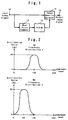
- the conventional image quality correcting circuit is designed so that the average image level (APL) for every 1 frame (or 1 field) is detected by the average value computer 10, and a corresponding correcting data is read out from the ROM 14 according to the APL, which serves as an address, in order to correct the inputted video signal, for being outputted from the output terminal 18, by the image quality corrector 16 according to the input/output conversion characteristic curve corresponding to the correcting data.
- the APL is obtained, for example, by dividing the sum of the products of the total number of display dots of each frame (or each field) and the occurrence frequency (number of times of occurrence) distribution of each luminance level by the total number of the dots.
- the display quality of the image can be improved where the brightness is evenly distributed in a given image but cannot be improved according to the content of the image because of a problem, that is, the lack of the consideration of the luminance level histogram (the luminance level occurrence frequency distribution).
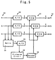
- the present applicant has already proposed the video signal correcting circuit as is shown in Fig.5 under the Laid-Open Japanese Patent Application No.8-23460.
- the inputted video signals SO comprising analog R (Red), G (Green) and B (Blue) signals
- A/D 20 Analog/Digital converter
- ROM 22 Read-Only Memory
- Y-signal luminance signal
- A/D 26 inputs to a histogram Circuit 28.
- the histogram circuit 28 counts the luminance level occurrence frequency (distribution) for each of the luminance level range divided into plural ranges (e.g., 4 ranges).
- a decoder 30 decodes the result of the count by the histogram circuit 28 for input, as a higher-rank address, to the ROM 22 for selecting the tone correcting characteristic data previously stored in the ROM 22, thereby correcting the tones of the inputted digital R, G and B signals to be outputted as the digital R, G and B signals S1.
- tone correction according to the occurrence frequency distribution of the luminance level of the inputted video signal can be made, but such a circuit still have a problem that the correcting characteristic corresponding to the occurrence frequency of each luminance level cannot be obtained.
- the present invention is made in order to solve the above problems of the prior art and is intended to provide an image quality correcting circuit applicable for the correction of all kinds of image based on a best correcting characteristic corresponding to the occurrence frequency of each luminance level.
- a first embodiment of the present invention is an image quality correcting circuit comprising a mean value computer 10 for computing the mean value of the luminance levels of every plural picture elements of the video signal inputted to a video signal input terminal 12, a counter 13 for counting the occurrence frequency of each of plural luminance levels counted by the mean value computer 10, a linear interpolator 15 for providing a correcting characteristic curve by the linear interpolation based on the counted value output point of the occurrence frequency counter 13, and an image quality corrector 16 for correcting the inputted video signal according to the correcting characteristic curve.
- the video signal inputted to a video signal input terminal 12 is processed by the mean value computer 10 for determining the mean value of (luminance levels) of plural picture elements for output, thereby computing the occurrence frequency of each luminance level.
- the linear interpolator 15 graphically provides a linear interpolation characteristic line consisting of a series of continuous segments with the luminance levels plotted on the y-axis and the occurrence frequency plotted on the x-axis.
- the image quality corrector 16 processes the video signal inputted from the video signal input terminal 12 to correct the image quality according to the correcting characteristic line provided by the linear interpolator and outputs the corrected video signal from the video signal output terminal 18.
- the second embodiment of the present invention is an image quality correcting circuit comprising the counter 13 for counting the occurrence frequency of the plural luminance levels sampled from the video signal inputted to the video signal input terminal 12 for each of the predetermined levels, a correcting curve generator 25 for generating a new correcting curve based on the data outputted from the counted value output point of the luminance level occurrence frequency counter 13 and the data of the predetermined set points inserted among the counting points, and the image quality corrector 16 for correcting the inputted video signal according to the correcting curve provided by the correcting curve generator 25.
- the data of every other occurrence frequency of (the luminance level) of the video signal inputted to the video signal input terminal 12 is used, and, on the other hand, the set data corresponding to the predetermined luminance levels plotted on the straight line connecting the graphic start point and end point is inputted so that these data can be rearranged in the order of the luminance level to interpolate one another for generating a Bezier curve.
- the video signal inputted from the video signal input terminal 12 is processed for the image quality correction according to the Bezier curve and outputted from the video signal output terminal 18.
- the occurrence frequency of the luminance level of each picture element within N number of frames is counted by the occurrence frequency counter for every plural set level ranges. Since the variation of the counted value of the occurrence frequency counter is controlled to the variation during a period ranging plural times of the N-frame period by the variation controller, the variation of the correcting characteristic line generated by the linear interpolator is also controlled.
- the image quality corrector by correcting the inputted video signal according to the variation-controlled correcting characteristic line.
- the fourth embodiment of the present invention comprises a counter for counting the occurrence frequency of the luminance level of each picture element within N frames for every plural set level range, a variation controller for controlling, for output, the variation of the counted value of the occurrence frequency counter to the variation during a period ranging plural times of the N number of frames, a correcting curve generator for generating a new correcting curve based on the counted value outputted from the variation controller and the predetermined set value, and an image quality corrector for correcting the inputted video signal according to the correcting curve generated by the correcting curve generator.
- the image quality corrector corrects the inputted video signal according to the variation-controlled correcting curve.
- a mean value computer for computing the mean value of the luminance levels for every m number of picture elements is provided so that the occurrence frequency counter counts the occurrence frequency of the luminance level for every predetermined plural set level range.
- the occurrence frequency counter is made to comprise a plurality of discriminators for determining whether the luminance level of each picture element corresponds to each of the plural set level ranges, a plurality of first counters for counting the frequency of discrimination made by each of the discriminators, a plurality of comparators for comparing the counted value of the first counter with predetermined reference value and for clearing the first counter by the output from the comparator, and a plurality of second counters for counting the frequency of the output from the comparator to determine the occurrence frequency (of the luminance level).
- the occurrence frequency counter comprises a plurality of discriminators for determining whether or not the luminance level computed by the mean value computer corresponds to each of the plural set level ranges, a plurality of first counters for counting the frequency of discrimination made by each discriminator, a plurality of comparators for comparing the counted value of the first counter and the predetermined reference value to clear the first counter by the output from the first comparator, and a plurality of second counters for counting the output frequency of the comparator to determine the occurrence frequency.
- the fifth embodiment of the present invention is an image quality correcting circuit comprising the occurrence frequency counter 13 for counting the occurrence frequency of the plural luminance levels sampled from the video signal inputted to the video signal input terminal 12 as to each of the predetermined luminance levels, a correcting characteristic point control circuit 29 for selectively outputting an upper limit value when the counted value of the correcting characteristic point outputted from the occurrence frequency counter 13 is greater than the predetermined upper limit value or outputting a lower limit value when the value is smaller than the (predetermined) lower limit value or outputting the counted value when the counted value is within the range from the upper limit value and the lower limit value, a correcting curve generator 48 for generating a correcting curve according to the output from the correcting control point control circuit 13, and the image quality corrector 16 for correcting the inputted video signal according to the correcting characteristic curve generated by the correcting curve generator 48, the image quality correcting circuit being further designed so that the upper limit value and the lower limit value of the counted value of the correcting characteristic point are set to an
- the sixth embodiment of the present invention is an image quality correcting circuit according to the fifth embodiment, wherein the upper limit value and the lower limit value are set to the upper limit value YHn and the lower limit value YLn, varying around the middle portion of a quadratic curve passing the graphic start point and graphic end point of a correcting characteristic diagram plotted on the x-axis, representing the inputted luminance level, and the y-axis, representing the outputted luminance level, of a rectangular coordinates.
- Fig.7 is a circuit diagram of the occurrence frequency counter showing a greater detail.
- the mean value computer 10 is designed to compute the means value of, for example, 16 luminance levels, thereby reducing the number of bits for the subsequent occurrence frequency counter 13.
- the occurrence frequency counter 13 comprises, for example, 16 discriminators 17 0 , 17 1 , ⁇ 17 15 , the first Counters 19 0 , 19 1 , ⁇ 19 15 respectively and sequentially connected to the discriminators, the comparators 21 0 , 21 1 , ⁇ 21 15 , the second counters 23 0 , 23 1 , ⁇ 23 15 , the comparison reference value input terminal 11 connected to the other input sides of the comparators; wherein the outputs from the comparators 21 0 , 21 1 , ⁇ 21 15 are returned, as clear signals, to the first counters 19 0 , 19 1 , ⁇ 19 15 in the preceding stage, while the outputs of the second counters 23 0 , 23 1 , ⁇ 23 15 are sent to the linear interpolator 15.
- the video signal inputted to the video input terminal 12 is processed by the mean value computer 10 to be outputted as the mean value of the luminance levels of 16 picture elements.
- the mean value is inputted to the discriminators 17 0 , 17 1 , ⁇ 17 15 , which correspond to respective luminance levels, in order to be determined whether it corresponds to one of the luminance levels. More particularly, the total of the occurrence frequencies within 1 frame is assumed to be 255, and the luminance level is divided into 16 levels for detection.
- the discriminator 17 0 determines whether (the luminance level) corresponds to (either) the level 0 or the level 1; the discriminator 17 1 determines whether (the luminance level) corresponds to one of the level 0 through the level 2; the same rule applies until it is determined whether (the luminance level) corresponds to one of the 0-level through the level 16.
- each of all the luminance levels corresponds to (one of) the level 0 through the level concerned.
- the occurrence frequency is counted by one of the subsequent first counters 19 0 , 19 1 , ⁇ 19 15 .
- the occurrence frequencies counted by the first counters 19 0 , 19 1 , ⁇ 19 15 are respectively inputted to the one sides of the subsequent comparators 21 0 , 21 1 , ⁇ 21 15 .
- the output from the comparison reference value input terminal 11 is inputted to the other sides (of the comparators). Therefore, when the occurrence frequency counted by each of the first counters 19 0 , 19 1 , ⁇ 19 15 is greater than the comparison reference value, the counting is carried out by the second counters 23 0 , 23 1 , ⁇ 23 15 , and the first counters 19 0 , 19 1 , ⁇ 19 15 are cleared.
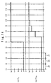
- the occurrence frequencies counted by the second counters 23 0 , 23 1 , ⁇ 23 15 are assumed to be as given below.
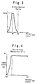
- the occurrence frequencies counted by these second counters 23 0 , 23 1 , ⁇ 23 15 respectively can be outputted as the correcting characteristic points when graphically represented with the luminance levels plotted on x-axis and the occurrence frequencies plotted on y-axis as shown in Fig.8.
- the data covering 16 levels obtained by adding each of the occurrence frequencies c0, c1, ⁇ cE to the start point 00 and the total number of occurrence frequencies (a fixed value) is sent to the linear interpolator 15, where the occurrence frequencies 00, c0, c1, ⁇ cE are sequentially connected with segments which are linearly interpolated to obtain a correcting characteristic line consisting of continuous segments.
- the image quality corrector 16 processes the video signal inputted from the video signal input terminal 12 for correcting image quality according to the correcting characteristic line provided by the linear interpolator 15 and outputs the corrected video signal from the video signal output terminal 18. More particularly, when the luminance level of the video signal inputted from the video signal input terminal 12 is x, the image quality correction processing is made according to the correcting characteristic line so that the corrected luminance level becomes y and (the corrected video signal) is outputted from the video signal output terminal 18.
- an optimum correcting characteristic can be obtained based on the occurrence frequency data of each luminance level, whereby the image quality correction processing adapted to the condition of the image can be made.
- the number of samples for determining the mean value by the mean value computer 10 is 16; the number of frame for obtaining the occurrence frequency data by the occurrence frequency counter is 1; the number of luminance levels is 16, but the present invention is not limited to this case.
- an optimum correcting characteristic adaptable to the occurrence frequency of each luminance level can be obtained, so that the image correction processing can be made suiting any type of image.
- the video signal input terminal 12, the mean value computer 10, the occurrence frequency counter 13, the image corrector 16 and the video signal output terminal 18 are similar to those of the first embodiment shown in Figs. 6 and 7.
- the second embodiment is characterized by the correcting curve generator 25 inserted between the appearance frequency counter 13 and the image quality corrector 16, the correcting curve generator being designed for generating a new correcting curve according to the occurrence frequency data of the video signal which is obtained based on the video signal inputted to the video signal input terminal 12 and counted by the occurrence frequency counter 13 through the mean value computer 10 and the set point data provided by the set point data input terminal 27.
- the correcting curve generator 25 comprises a circuit designed for generating a Bezier curve passing the start point 00 and the end point TF and based on the plural points comprising the occurrence frequency and the set point given alternately.
- the image quality corrector 16 processes the video signal inputted from the video signal input terminal 12 to correct the image quality according to the correcting curve provided from the correcting curve generator 25 and outputs the corrected video signal from the video signal output terminal 18.
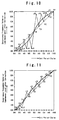
- the set point data from the set point data input terminal 27 is sampled from the straight line connecting the start point 00 and the end point TF, but the sampling method is not limited to this case; for instance, as in the case of the characteristic line represented by the solid line in Fig.10, the contrast between the bright portion and the dark portion of the image can be emphasized by sampling the set points from the S-shape curve including the upwardly swelled portion representing the higher (luminance) levels and the sagged portion representing the lower (luminance) levels, or the contrast between the bright portion and the dark portion can be weakened by using the set points having inverse characteristic.
- the present embodiment is not limited to the case where the appearance frequency data and the set point data are arranged alternately; for instance, the appearance frequency data and the set point data may be arranged at a ratio of 2 to 1 to emphasize the video signal data, or the both may be arranged at a ratio of 1 to 2 to emphasize the set point data.
- the optimum correcting characteristic can be obtained according to the appearance frequency data for each (luminance) level to make image quality correction processing applicable to any kind of image. Further, by selecting any given points of correcting characteristic curve, the characteristic curve can be varied according to the purpose or preference.
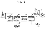
- Fig.12 12 denotes the video signal input terminal; 10, the mean value computer; 13, the occurrence frequency counter; 11, reference value input terminal; 15, linear interpolator; 16, image quality corrector; 18, video signal output terminal; 31, variation controller.
- the variation controller 31 comprises the 15 variation controllers 31 0 , 31 1 , ⁇ 31 14 ;
- the variation controller 31 0 comprises the (difference detectors) 33 0 , constant multiplier 35 0 , adder 37 0 and N-frame delayer 39 0 ;
- the variation controller 31 1 comprises the (difference detectors) 33 1 , constant multiplier 35 1 , adder 37 1 and N-frame delayer 39 1 , and others comprise similar parts;
- the variation controller 31 14 comprises the (difference detector) 33 14 , constant multiplier 35 14 , adder 37 14 and N-frame delayer 39 14 .
- the (difference detectors) 33 0 , 33 1 , ⁇ 33 14 output the differences between the occurrence frequencies (counted values) outputted from the second counters 23 0 , 23 1 , ⁇ 23 14 and the output values of N-frame delayers 39 0 , 39 1 , ⁇ 39 14 ;
- the adders 37 0 , 37 1 , ⁇ 37 14 add the output values of the constant multipliers 35 0 , 35 1 , ⁇ 35 14 to the output values of the N-frame delayers 39 0 , 39 1 , ⁇ 39 14 ;
- the N-frame delayers 39 0 , 39 1 , ⁇ 39 14 not only delay the sums obtained by the adders 37 0
- the video signal input terminal 12, the mean value computer 10, the appearance frequency counter 13, the image quality corrector 16, the video signal output terminal 18 and the variation controller 31 are similar to those of the embodiment 3 shown in Fig.12 and Fig.13.
- the fourth embodiment is characterized by that a correcting curve generator 25 provided replacing the linear interpolator 15 shown in Fig.12.
- the correcting curve generator 25, inserted between the variation controller 31 and the image quality corrector 16, is designed to generate a new correcting curve based on the occurrence frequency, which is counted by the occurrence frequency counter 13 and whose variation is controlled by the variation controller 31, and the set point data, which is provided from the set point data input terminal 27.
- the correcting curve generator 25 is, for example, composed of a circuit designed for generating a Bezier curve passing the start point 00 and the end point TF based on plural points representing the occurrence frequency and set points arranged alternately.
- the correcting characteristic point control circuit 29 comprises a control range comparator 43, a control range setter 46, a control counter for specifying the order of processing and a correcting characteristic point selector 47;
- the control range comparator 43 comprises the upper limit comparator 41a for comparing the uncorrected correcting characteristic point data (Pn) with the upper limit value (an + w) at that characteristic point and the lower limit comparator 42a for comparing the Pn with the lower limit value (an - w) at that characteristic point;
- the control range setter 46 comprises an upper limit setter 44a for setting the upper limit value (an + w) and a lower limit setter 45a for setting the lower limit value (an - w);
- the correcting characteristic point selector 47 is a circuit for selecting the terminal x for Pn of the occurrence frequency counter 13, the terminal y for the upper limit value (an + w) of the upper limit setter 44a and the terminal z for the lower limit value (an - w) of the lower limit setter 45a
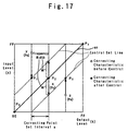
- the straight line connecting the start point and the end point in an rectangular coordinates with its x-axis representing the output level of the luminance and its y-axis representing the input level of the luminance, represents an ideal correcting characteristic line in the case where there is no deviation with respect to the occurrence frequencies of the input levels of the inputted video signals, wherein w represents a certain distribution range around the ideal characteristic line.
- an + w and an - w respectively represent the control set lines representing the upper limit and the lower limit having certain extent lying parallel to the ideal straight line, as shown by the dotted lines in Fig.17.
- the video signals inputted to the video signal input terminal 12 are processed by the mean value computer 10 for computing the mean values of the luminance levels of every 16 picture elements at various points, which are to be output sequentially.
- the detected mean values are counted by the occurrence frequency counter.
- the uncontrolled correcting characteristic point data Pn from the occurrence frequency counter 13 in inputted not only to the contact x of the correcting characteristic point selector 47 but also inputted to the one side of the subsequent upper limit comparator 41a and that of the lower limit comparator 42a as an input. Further, the upper limit value an + w and the lower limit value an - w respectively corresponding to the numbers of the correcting characteristic point data Pn from the control counter 40 are inputted to the other sides of these upper limit comparator 41a and the lower limit comparator 42a respectively.
- the upper limit comparator 41a outputs the signal for switching to the contact y of the correcting characteristic point selector 47, and, when Pn ⁇ an - w, the lower limit comparator 42a outputs the signal for switching to the contact z of the correcting characteristic selector 47.
- the switching signal is outputted from the upper limit comparator 41a to switch the contact of the correcting characteristic point selector 47 to the contact y and the an + w from the upper limit setter 44a is outputted to the correcting curve generator 48.
- the correcting curve generator 48 generates a corrected correcting curve on the upper limit set line P1 shown in Fig.17 according to the an + w outputted from the upper limit setter 44a to serve as an address and the set point data inputted from the set point data input terminal 49, and the corrected correcting curve is outputted to the image quality corrector 16.
- the video signal inputted from the video signal input terminal 12 is corrected by the image quality corrector 16 according to the correcting curve, and the corrected video signal is outputted to the output terminal 18.
- the deterioration of the image quality can be prevented by controlling the point y whose distribution of occurrence frequencies has some dispersion within a set range.
- the switching signal is outputted from the lower limit comparator 42a to switch the contact of the correcting characteristic point selector 47 to the contact z, and the an - w from the lower limit setter 45a is outputted to the correcting curve generator 48.
- the correcting curve generator 48 generates a corrected correcting curve on the point P3 the lower limit setting line shown in Fig.17 according to the output an - w to serve as an address from the lower limit setter 45a and the set point data inputted from the set point data input terminal 49, and the corrected correcting curve is outputted to the image quality corrector 16.
- the image quality corrector 16 corrects the video signal inputted from the video signal input terminal 12 according to the corrected correcting curve, and the corrected video signal is outputted to the output terminal 18. As discussed above, the deterioration of the image quality can be prevented by controlling the z point whose distribution of occurrence frequency is dispersed within a set range.
- the switching signal from the upper limit comparator 41a and the lower limit comparator 42a will not be outputted, and the Pn from the occurrence counter 13 is outputted to the correcting curve generator 48.
- the correcting curve generator 48 outputs the uncorrected correcting circuit curve to the image quality corrector 16, and the video signal from the video signal input terminal 12 outputs the uncorrected video signal to the output terminal 18.
- the generation of the correcting characteristic line having an extreme inclination and the image quality deterioration due to the inclination of the occurrence frequency can be prevented to obtain an optimum correcting characteristic.
- the range of the upper limit value + w and the limit of the lower limit value - w are assumed to be fixed.
- the upper limit range and the lower limit range are set for each correcting characteristic point.
- the video signal input terminal 12, the mean value computer 10, the occurrence frequency counter 13, the image quality corrector 16, the video signal output terminal 18, the correcting curve generator 48 and the set point data input terminal 49 are similar to those in the case of the fifth embodiment.
- the second embodiment is characterized by the generation of a quadratic curve according to the correcting characteristic points representing the upper limit value YHn and the lower limit value YLn being 0 respectively at the start point 0, the upper limit value YHn increasing gradually with respect to the straight line an until the intermediate position, and the lower limit value YLn decreasing gradually with respect to the straight line an to pass the end point FF again.
- the straight line an connects the start point and the end point FF in the correcting characteristic diagram and represents an ideal correcting characteristic line where the occurrence frequencies of the input levels of the inputted video signals are free of the inclination.
- the switching signal is outputted from the upper limit comparator 41b to switch the contact of the correcting characteristic point selector 47 to the contact y, and the YH1 from the upper limit comparator 44b is outputted to the correcting curve generator 48.
- the correcting curve generator 48 generates a corrected correcting curve at the point P1 of the upper limit set line, shown in Fig.19, according to the output, serving as an address, of the upper limit setter 44b and based on the set point data inputted from the set point data input terminal 49 and outputs the corrected correcting curve to the image quality corrector 16.
- the image quality corrector 16 corrects the video signal from the video signal input terminal 12 according to the correcting curve and outputs the corrected video signal to the output terminal 18. In this way, the deterioration of the image quality is prevented by controlling the point y, whose distribution of occurrence frequency is inclined, within the set range.
- the switching signal is outputted from the lower limit comparator 42b to switch the contact of the correcting characteristic selector 47 to the contact z, and the YL3 from the lower limit setter 45b is outputted to the correcting curve generator 48.
- the correcting curve generator 48 generates a corrected correcting curve at the point P3 on the lower limit set line, shown in Fig.19, according to the output, serving as an address, from the lower limit setter 45b and based on the set point data inputted from the set point data input terminal 49 and outputs the corrected correcting curve to the image quality corrector 16.
- the image quality corrector 16 corrects the video signal from the video signal input terminal 12 according to the corrected correcting curve and output the corrected video signal to the output terminal 18. In this way, the deterioration of the image quality is prevented by controlling the z point, whose distribution of occurrence frequency is inclined, within the set range.
- the switching signal will not be outputted from the upper limit comparator 41a and the lower limit comparator 42a, and the Pn from the occurrence frequency counter 13 is outputted to the correcting curve generator 48.
- the correcting curve generator 48 outputs uncorrected correcting curve to the image quality corrector 16, and the video signal from the video signal input terminal 12 is outputted to the output terminal 18 without being corrected.
- the optimum correcting characteristic adapted to the appearance frequency data of each level, and image quality correction processing suiting any kind of image can be made available. Further, according to this embodiment, not only the an extreme variation of the correcting curve can be prevented according to correcting characteristic point but also the correcting curve can be varied either intentionally or by the preference.
- the number of samples for obtaining the mean value to be computed by the mean value computer 10 is set to 16, the number of frame for obtaining the occurrence frequency data from the occurrence frequency counter 13 to 1 frame, and the number of degrees of the luminance level to 16, but the present invention is not limited to these cases.
- the image quality correcting circuit is not only capable of obtaining the optimum correcting characteristic according to the occurrence frequency data of each (luminance) level so that the image quality correction processing suiting any kind of image but also capable of preventing extreme variation of correcting curve or varying the correcting curve either intentionally or preferentially. Further, even when the distribution of the occurrence frequency of the luminance level varies largely at the time of the switching of the image or when displaying moving images, such extreme variations and resultant image quality deterioration can be prevented by implementing the image quality correction processing according to the present invention.
Landscapes
- Engineering & Computer Science (AREA)
- Multimedia (AREA)
- Signal Processing (AREA)
- Physics & Mathematics (AREA)
- General Physics & Mathematics (AREA)
- Theoretical Computer Science (AREA)
- Computer Hardware Design (AREA)
- Picture Signal Circuits (AREA)
- Liquid Crystal Display Device Control (AREA)
- Control Of Indicators Other Than Cathode Ray Tubes (AREA)
Abstract
Description
Claims (23)
- An image quality correcting circuit comprising an (luminance level) occurrence frequency counter 13 for counting the occurrence frequencies of the plural luminance levels sampled from the video signals inputted to a video signal input terminal 12, a linear interpolator 15 for generating a correcting characteristic line by making the liner interpolation based on the output points of counted values of the occurrence frequency counter 13, and an image quality corrector 16 for correcting the inputted video signals according to the correcting characteristic points.
- An image quality correcting circuit comprising a mean value computer 10 for computing the mean value of the luminance levels of every plural picture elements sampled from the video signals inputted from the video signal input terminal 12, the occurrence frequency counter 13 for counting the occurrence frequencies of the predetermined plural luminance levels processed by the mean value computer 10, the linear interpolator 15 for generating the correcting characteristic line by making the linear interpolation based on the counted value points outputted from the occurrence frequency counter 13, and the image quality corrector 16 for correcting the inputted video signals according to the correcting characteristic line.
- The image quality correcting circuit defined in claim 1 or claim 2 comprising a plurality of discriminators 17 for determining the occurrence frequencies of plural luminance levels for every predetermined levels, a plurality of a first counters 19 for counting the occurrence frequencies for every predetermined levels discriminated by the discriminators 17, a plurality of comparators 21 for comparing the outputs of the first counters 19 with the reference values for comparison outputted from a reference value for comparison input terminal 11 to clear the first counters 19 by the outputs for comparison, a plurality of second counters 23 for counting the outputs of the comparators 21.
- The image quality correcting circuit defined in claim 3, wherein the occurrence frequency counter 13 comprises the discriminators 17, the first counters, the comparators 21 and the second counters 23, each comprising 16 series circuits, connected with one another.
- An image quality correcting circuit comprising the occurrence frequency counter 13 for counting the occurrence frequencies of plural luminance levels sampled from the video signals inputted to the video signal input terminal 12, a correcting curve generator 25 for generating a new correcting curve based on the counted value output points (data) of the occurrence frequency counter 13 and the set points (data) previously inserted among the counted value points, and the image quality correcting circuit 16.
- An image quality correcting circuit comprising the mean value computer 10 for computing the mean value of the luminance levels of every plural picture elements of the video signal inputted to the video signal input terminal 12, the occurrence frequency counter 13 for counting the occurrence frequencies of plural luminance levels computed by the mean value computer 10 for every predetermined level, the correcting curve generator 25 for generating a new correcting curve based on the counted value output points (data) of the occurrence frequency counter 13 and the predetermined set points (data) inserted among the counted value data, and the image quality corrector 16 for correcting the video signal according to the correcting curve generated by the correcting curve generator 25.
- The image quality correcting circuit defined in claim 5 or claim 6, wherein the correcting curve generator 25 is designed for generating a new correcting curve by inserting either the counted value output point data of the occurrence frequency counter 13 or the predetermined set point data among the other data, for example, between every other data or between every other plural data.
- The image quality correcting circuit defined in claim 5 or claim 6, wherein the correcting curve generator 25 comprises a circuit designed for generating a Bezier curve passing the start point and the end point based on the counted value output point data of the occurrence frequency counter 13 and the predetermined set point data, either one of which is inserted among the other, for example, between every other data or between every other plural data.
- An image quality correcting circuit comprising an occurrence frequency counter for counting the occurrence frequencies of the luminance levels of the picture elements of the inputted video signal within N number (N = any integer of 1 or more) of frames, a variation controller controlling, for output, the variation of the counted value of the occurrence frequency counter within a period ranging over several times the N-frame period, a linear interpolator for forming a correcting characteristic line by linear interpolation based on the counted value outputted from the variation controller, and an image quality corrector for correcting the inputted video signal according to the correcting characteristic line formed by the linear interpolator.
- An image quality correcting circuit comprising a mean value computer for computing the mean value of the luminance levels of m number (m = any integer of 2 or more) of picture elements of the inputted video signal, an occurrence frequency counter for counting the occurrence frequencies of the luminance levels computed by the mean value computer within the N-frame period (N = any integer of 1 or more) for every plural set level ranges, a variation controller for controlling, for output, the variation of the counted value of the occurrence frequency counter ranging over plural number of times of the N-frame period, a liner interpolator for forming the correcting characteristic line by the linear interpolation based on the counted value outputted from the variation controller, and an image quality corrector for correcting the inputted video signal according to the correcting characteristic line formed by the linear interpolator.
- An image quality correcting circuit comprising an occurrence frequency counter for counting the occurrence frequencies of the luminance levels of the picture elements of the inputted video signals within N number (N = any integer of 1 or more) of frames, a variation controller for controlling, for output, the variation of the counted value of the occurrence frequency counter ranging over plural number of times of the N-frame period, a correcting curve generator for generating a new correcting curve based on the counted values outputted from the variation controller and the predetermined set values, and an image quality corrector for correcting the inputted video signal according to the correcting curve generated by the correcting curve generator.
- An image quality correcting circuit comprising a mean value computer for computing the mean value of the luminance levels of the m number (m = any integer of 2 or more) of picture elements of the inputted video signals, an occurrence frequency counter for counting the occurrence frequencies of the luminance levels computed by the mean value computer ranging over N-frame period (N = any integer of 1 or more) for every plural set levels, a variation controller for controlling, for output, the variation of the counted value of the occurrence frequency counter ranging over the period of plural times of the N-frame period, a correcting curve generator for generating a new correcting curve based on the counted values outputted from the variation controller and predetermined set values, and an image quality corrector for correcting the inputted video signal according to the correcting curve generated by the correcting curve generator.
- The image quality correcting circuit defined in claim 9 or claim 11, wherein the occurrence frequency counter comprises a plurality of discriminators for determining whether or not the luminance level of each picture element of the inputted video signal corresponds to each of plural set levels, a plurality of the first counters for counting the number of times of determination made by each discriminator, a plurality of comparators for comparing the counted value of the first counter with the predetermined reference value for comparison to clear the first counter by the comparison output, and a plurality of the second counters for counting the number of times of the output of the comparator for use as the appearance frequency.
- The image quality correcting circuit defined in claim 10 or claim 12, wherein the occurrence frequency counter comprises a plurality of discriminators for determining whether or not the luminance levels computed by the mean value computer respectively correspond to the set level ranges, a plurality of the first counters for counting the number of times of determinations made by the discriminators, a plurality of comparators for comparing the counted values of the first counters with the predetermined reference values for comparison to clear the first counters by the output for comparison, and a plurality of the second counters for counting the number of times of outputs of the comparators for use as the occurrence frequencies.
- The image quality correcting circuit defined in claim 9, claim 10, claim 11 or claim 12, wherein the variation controller comprises a difference detector, a constant multiplier, an adder and a N-frame delayer; the difference detector outputs the difference between the counted value of the occurrence frequency counter and the output value of the N-frame delayer; the constant multiplier multiplies the output value of the difference detector by 1/X (X = any integer of 2 or more) for output; the adder adds the output value of the N-frame delayer to the output value of the constant multiplier; the N-frame delayer delays the sum obtained by the adder by N frames not only for output to the difference detector and the adder but also for output as the variation-controlled output.
- The image quality correcting circuit defined in claim 13, wherein the variation controller comprises a difference detector, a constant multiplier, an adder and an N-frame delayer; the difference detector outputs the difference between the counted value of the second counter and the output value of the N-frame delayer; the constant multiplier multiplies the output value of the N-frame delayer by coefficient 1/X (X = any integer of 2 or more) for output; the adder adds the output value of the constant multiplier to the output value of the N-frame delayer; the N-frame delayer delays the sum obtained by the adder by N number of frames not only for output to the difference detector and the adder but also for variation-controlled output.
- The image quality correcting circuit defined in claim 14, wherein the variation controller comprises a difference detector, a constant multiplier, an adder and an N-frame delayer; the difference detector outputs the difference between the counted value of the second counter and the output of the N-frame delayer; the constant multiplier multiplies the output value of the N-frame delayer by the coefficient 1/X (X = any integer of 1 or more) for output; the adder adds the output value of the constant multiplier to the output value of the N-frame delayer; the N-frame delayer delays the sum obtained by the adder by N frames not only for output to the difference detector but also for variation-controlled output.
- An image quality correcting circuit comprising the appearance frequency counter 13 for counting the occurrence frequency data of the plural luminance levels sampled from the video signal inputted to the video signal input terminal 12 for every predetermined level, the correcting characteristic point 29 for selectively outputting the upper limit value when the counted value of the correcting characteristic point outputted from the occurrence frequency counter 13 is greater than the predetermined upper limit value, while selectively outputting the lower limit value when the same is smaller than the lower limit value, the correcting curve generator 48 for generating a correcting curve according to the output of the correcting characteristic point control circuit 29, and the image quality corrector 16 for correcting the inputted video signal according to the correcting characteristic line generated by the correcting curve generator 48.
- The image quality correcting circuit defined in claim 18, wherein the occurrence frequency counter comprises the mean value computer for computing the mean value of the luminance levels of the plural picture elements of the video signal inputted to the video signal input terminal 12 and the counter for counting the occurrence frequencies of plural luminance levels computed by the mean value computer 10 for every predetermined level.
- The image quality correcting circuit defined in claim 18 or claim 19, wherein the correcting characteristic point control circuit 29 comprises a control range comparator 43 for comparing the counted value of the correcting characteristic point and the linearly varying upper limit value and lower limit value, a correcting characteristic point selector 47 for selecting the upper limit value, lower limit value or the counted value of the occurrence frequency counter 13 according to the output of the control range comparator 43, and a control counter 40 for controlling the order of processing of the correcting characteristic point.
- The image quality correcting circuit defined in claim 20, wherein the control range comparator 43 comprises the upper limit comparator 41a for comparing the counted value Pn of the correcting characteristic point and the linearly varying upper limit value an + w and the lower limit comparator 42a for comparing the counted value Pn of the correcting characteristic point and the lower limit value an - w, and the control range setter 46 comprises the upper limit setter 44a for setting the upper limit value an + w and the lower limit setter 45a for setting the lower limit value an - w.
- The image quality correcting circuit defined in claim 18 or claim 19, wherein the correcting characteristic control circuit 29 comprises the control range comparator 43 for comparing the counted value Pn of the correcting characteristic point with the upper limit values and the lower limit values on the correcting characteristic graphic lines passing the start point and the end point, which vary quadratically around intermediate portions thereof, the correcting characteristic point selector 47 for selecting the upper limit value, lower limit value or counted value of the occurrence frequency counter 13, and the control counter 40 for controlling the order of processing for the correcting characteristic points.
- The image quality correcting circuit defined in claim 22, wherein the control range comparator 43 comprises the upper limit comparator 41b for comparing the counted value Pn of the correcting characteristic point with the quadratically variable upper limit value YHn, and the lower limit comparator 42b for comparing the counted value Pn of the correcting characteristic point with the lower limit value YLn, while the control range setter 46 comprises the upper limit setter 44b for setting the upper limit value YHn and the lower limit setter 45b for setting the lower limit YLn.
Applications Claiming Priority (7)
| Application Number | Priority Date | Filing Date | Title |
|---|---|---|---|
| JP9201499 | 1999-03-31 | ||
| JP09201499A JP4590043B2 (en) | 1999-03-31 | 1999-03-31 | Image quality correction circuit |
| JP28063399A JP2001103338A (en) | 1999-09-30 | 1999-09-30 | Image quality correction circuit |
| JP28063399 | 1999-09-30 | ||
| JP30922499A JP2001125535A (en) | 1999-10-29 | 1999-10-29 | Image quality correction circuit |
| JP30922499 | 1999-10-29 | ||
| PCT/JP2000/001872 WO2000060566A1 (en) | 1999-03-31 | 2000-03-27 | Image quality correcting circuit |
Publications (2)
| Publication Number | Publication Date |
|---|---|
| EP1085494A1 true EP1085494A1 (en) | 2001-03-21 |
| EP1085494A4 EP1085494A4 (en) | 2009-01-07 |
Family
ID=27306907
Family Applications (1)
| Application Number | Title | Priority Date | Filing Date |
|---|---|---|---|
| EP00911390A Withdrawn EP1085494A4 (en) | 1999-03-31 | 2000-03-27 | Image quality correcting circuit |
Country Status (8)
| Country | Link |
|---|---|
| US (1) | US7012625B1 (en) |
| EP (1) | EP1085494A4 (en) |
| KR (1) | KR100732014B1 (en) |
| CN (1) | CN1163057C (en) |
| AU (1) | AU769305B2 (en) |
| CA (1) | CA2333622A1 (en) |
| TW (1) | TW531721B (en) |
| WO (1) | WO2000060566A1 (en) |
Cited By (2)
| Publication number | Priority date | Publication date | Assignee | Title |
|---|---|---|---|---|
| EP1761040A2 (en) | 2005-08-31 | 2007-03-07 | Sony Corporation | Apparatus, method and computer program for taking an image and apparatus, method and computer program for processing an image |
| EP1857996A1 (en) * | 2006-05-17 | 2007-11-21 | NEC Electronics Corporation | Display device, display panel driver and method of driving a display panel |
Families Citing this family (14)
| Publication number | Priority date | Publication date | Assignee | Title |
|---|---|---|---|---|
| KR20040040699A (en) * | 2002-11-07 | 2004-05-13 | 삼성전자주식회사 | Apparatus and Method for compansation contrast |
| KR100513273B1 (en) * | 2003-07-04 | 2005-09-09 | 이디텍 주식회사 | Apparatus and method for real-time brightness control of moving images |
| US20050212726A1 (en) * | 2004-03-16 | 2005-09-29 | Pioneer Plasma Display Corporation | Method, display apparatus and burn-in reduction device for reducing burn-in on display device |
| JP2006101421A (en) * | 2004-09-30 | 2006-04-13 | Toshiba Corp | Video signal processing circuit |
| JP2006154452A (en) * | 2004-11-30 | 2006-06-15 | Toshiba Corp | Video signal processing apparatus and gradation step detection method |
| JP4325552B2 (en) | 2004-12-24 | 2009-09-02 | セイコーエプソン株式会社 | Image processing apparatus, image processing method, and image processing program |
| JP4533330B2 (en) * | 2005-04-12 | 2010-09-01 | キヤノン株式会社 | Image forming apparatus and image forming method |
| JP2006319634A (en) * | 2005-05-12 | 2006-11-24 | Toshiba Corp | Video signal processing apparatus and gradation step detection method |
| JP4389882B2 (en) * | 2006-01-27 | 2009-12-24 | セイコーエプソン株式会社 | LIGHT EMITTING DEVICE, IMAGE PROCESSING DEVICE, AND ELECTRONIC DEVICE |
| JP5196731B2 (en) * | 2006-04-20 | 2013-05-15 | キヤノン株式会社 | Image processing apparatus and image processing method |
| JP4795473B2 (en) | 2009-06-29 | 2011-10-19 | キヤノン株式会社 | Image processing apparatus and control method thereof |
| WO2012026110A1 (en) | 2010-08-26 | 2012-03-01 | パナソニック株式会社 | Video-display control device |
| JP5868119B2 (en) * | 2010-12-09 | 2016-02-24 | キヤノン株式会社 | Image processing apparatus, radiation imaging system, image processing method, and recording medium |
| TWI483555B (en) * | 2011-12-15 | 2015-05-01 | Silicon Motion Inc | Testing apparatus and method for testing analog-to-digital converters |
Family Cites Families (16)
| Publication number | Priority date | Publication date | Assignee | Title |
|---|---|---|---|---|
| JPS58130099A (en) | 1983-01-14 | 1983-08-03 | 中松 義郎 | Dryer for bedding |
| JPS6339280A (en) * | 1986-08-04 | 1988-02-19 | Mitsubishi Electric Corp | Picture processor |
| US4979136A (en) * | 1988-03-01 | 1990-12-18 | Transitions Research Corporation | Processing system and method for enhancing image data |
| JPH03255785A (en) * | 1990-03-06 | 1991-11-14 | Konica Corp | Picture processor |
| JPH06339280A (en) * | 1993-05-27 | 1994-12-06 | Hitachi Ltd | Low-loss snubber circuit for power converter |
| JPH0773308A (en) * | 1993-09-03 | 1995-03-17 | Matsushita Electric Ind Co Ltd | Digital image processor |
| JPH07162715A (en) * | 1993-12-10 | 1995-06-23 | Fujitsu General Ltd | Digital gamma correction method |
| JP3201449B2 (en) * | 1994-04-06 | 2001-08-20 | 株式会社富士通ゼネラル | Image display processing method and apparatus for electronic display |
| JP3255258B2 (en) * | 1994-06-20 | 2002-02-12 | 株式会社富士通ゼネラル | Image display device |
| JPH0823460A (en) * | 1994-07-11 | 1996-01-23 | Fujitsu General Ltd | Dynamic gamma correction circuit |
| JPH08317250A (en) * | 1995-05-19 | 1996-11-29 | Fujitsu General Ltd | Dynamic video control circuit |
| JP3501252B2 (en) * | 1995-06-16 | 2004-03-02 | 三菱電機株式会社 | Gradation correction device |
| JP3003561B2 (en) * | 1995-09-25 | 2000-01-31 | 松下電器産業株式会社 | Gradation conversion method and circuit, image display method and apparatus, and image signal conversion apparatus |
| KR100213094B1 (en) * | 1997-02-21 | 1999-08-02 | 윤종용 | Histogram and CDF Extraction Method for Image Enhancement and Its Circuit |
| JP3267200B2 (en) * | 1997-07-11 | 2002-03-18 | 松下電器産業株式会社 | Image processing device |
| US6504954B1 (en) * | 1999-02-05 | 2003-01-07 | Raytheon Company | Closed loop piecewise-linear histogram specification method and apparatus |
-
2000
- 2000-03-27 CN CNB008004242A patent/CN1163057C/en not_active Expired - Fee Related
- 2000-03-27 EP EP00911390A patent/EP1085494A4/en not_active Withdrawn
- 2000-03-27 AU AU33290/00A patent/AU769305B2/en not_active Ceased
- 2000-03-27 KR KR1020007013488A patent/KR100732014B1/en not_active Expired - Fee Related
- 2000-03-27 US US09/700,495 patent/US7012625B1/en not_active Expired - Fee Related
- 2000-03-27 WO PCT/JP2000/001872 patent/WO2000060566A1/en not_active Ceased
- 2000-03-27 CA CA002333622A patent/CA2333622A1/en not_active Abandoned
- 2000-03-28 TW TW089105647A patent/TW531721B/en active
Cited By (6)
| Publication number | Priority date | Publication date | Assignee | Title |
|---|---|---|---|---|
| EP1761040A2 (en) | 2005-08-31 | 2007-03-07 | Sony Corporation | Apparatus, method and computer program for taking an image and apparatus, method and computer program for processing an image |
| EP1761040A3 (en) * | 2005-08-31 | 2008-03-12 | Sony Corporation | Apparatus, method and computer program for taking an image and apparatus, method and computer program for processing an image |
| US7742637B2 (en) | 2005-08-31 | 2010-06-22 | Sony Corporation | Apparatus, method, and program for taking an image, and apparatus, method, and program for processing an image |
| EP1857996A1 (en) * | 2006-05-17 | 2007-11-21 | NEC Electronics Corporation | Display device, display panel driver and method of driving a display panel |
| KR100887304B1 (en) * | 2006-05-17 | 2009-03-06 | 엔이씨 일렉트로닉스 가부시키가이샤 | Display device and display panel driver |
| US7973973B2 (en) | 2006-05-17 | 2011-07-05 | Renesas Electronics Corporation | Display device, display panel driver and method of driving display panel |
Also Published As
| Publication number | Publication date |
|---|---|
| WO2000060566A1 (en) | 2000-10-12 |
| AU769305B2 (en) | 2004-01-22 |
| TW531721B (en) | 2003-05-11 |
| CN1306657A (en) | 2001-08-01 |
| CA2333622A1 (en) | 2000-10-12 |
| AU3329000A (en) | 2000-10-23 |
| US7012625B1 (en) | 2006-03-14 |
| KR20010043934A (en) | 2001-05-25 |
| EP1085494A4 (en) | 2009-01-07 |
| KR100732014B1 (en) | 2007-06-25 |
| CN1163057C (en) | 2004-08-18 |
Similar Documents
| Publication | Publication Date | Title |
|---|---|---|
| US7012625B1 (en) | Image quality correcting circuit | |
| EP0630154B2 (en) | Television receiver capable of enlarging and compressing image | |
| EP1067507B1 (en) | Image display | |
| CA2417169C (en) | Image processing apparatus and image processing method | |
| US7394932B2 (en) | Video signal processor and method of processing video signal | |
| JP3501252B2 (en) | Gradation correction device | |
| US8421917B2 (en) | Image processing apparatus and method of controlling the same | |
| US20050140829A1 (en) | Signal processing apparatus, image display apparatus and signal processing method | |
| JP3661168B2 (en) | Gradation correction apparatus, gradation correction method, and video display apparatus | |
| US20030071917A1 (en) | Motion adaptive de-interlacing method and apparatus | |
| JP2001343957A (en) | Liquid crystal display | |
| US6084560A (en) | Image display for dither halftoning | |
| US7304672B2 (en) | Contour correcting video signal processing apparatus | |
| JP4216830B2 (en) | Video processing apparatus and method, and computer-readable storage medium | |
| US6636229B2 (en) | Gradation correction circuit, and γ correction apparatus | |
| US20060013499A1 (en) | Converting the resolution of an image using interpolation and displaying the converted image | |
| JPH05219399A (en) | Parabolic waveform generating circuit | |
| US20060045375A1 (en) | Image processing device, image display device, image processing method, and image display method | |
| JP3630093B2 (en) | Video data correction apparatus and video data correction method | |
| US7548279B2 (en) | Video signal processor | |
| EP0851388B1 (en) | Picture processing apparatus and method | |
| EP0835583B1 (en) | Spline waveform generation | |
| RU2251160C2 (en) | Image quality correction circuit | |
| JP2001125535A (en) | Image quality correction circuit | |
| JP3080019B2 (en) | Video signal processing device |
Legal Events
| Date | Code | Title | Description |
|---|---|---|---|
| PUAI | Public reference made under article 153(3) epc to a published international application that has entered the european phase |
Free format text: ORIGINAL CODE: 0009012 |
|
| 17P | Request for examination filed |
Effective date: 20001221 |
|
| AK | Designated contracting states |
Kind code of ref document: A1 Designated state(s): AT BE CH CY DE DK ES FI FR GB GR IE IT LI LU MC NL PT SE |
|
| RBV | Designated contracting states (corrected) |
Designated state(s): DE ES FR GB IT NL |
|
| RAP1 | Party data changed (applicant data changed or rights of an application transferred) |
Owner name: CANON KABUSHIKI KAISHA |
|
| A4 | Supplementary search report drawn up and despatched |
Effective date: 20081210 |
|
| RIC1 | Information provided on ipc code assigned before grant |
Ipc: G09G 3/20 20060101AFI20001017BHEP Ipc: G09G 3/36 20060101ALI20081204BHEP Ipc: G06T 5/00 20060101ALI20081204BHEP Ipc: H04N 5/57 20060101ALI20081204BHEP |
|
| 17Q | First examination report despatched |
Effective date: 20090320 |
|
| STAA | Information on the status of an ep patent application or granted ep patent |
Free format text: STATUS: THE APPLICATION IS DEEMED TO BE WITHDRAWN |
|
| 18D | Application deemed to be withdrawn |
Effective date: 20100216 |