EP1085309A2 - Vibrating quartz diaphragm pressure sensor - Google Patents
Vibrating quartz diaphragm pressure sensor Download PDFInfo
- Publication number
- EP1085309A2 EP1085309A2 EP00307469A EP00307469A EP1085309A2 EP 1085309 A2 EP1085309 A2 EP 1085309A2 EP 00307469 A EP00307469 A EP 00307469A EP 00307469 A EP00307469 A EP 00307469A EP 1085309 A2 EP1085309 A2 EP 1085309A2
- Authority
- EP
- European Patent Office
- Prior art keywords
- crystal
- sensor
- resonator element
- axis
- bores
- Prior art date
- Legal status (The legal status is an assumption and is not a legal conclusion. Google has not performed a legal analysis and makes no representation as to the accuracy of the status listed.)
- Withdrawn
Links
- 239000010453 quartz Substances 0.000 title claims description 13
- VYPSYNLAJGMNEJ-UHFFFAOYSA-N silicon dioxide Inorganic materials O=[Si]=O VYPSYNLAJGMNEJ-UHFFFAOYSA-N 0.000 title claims description 13
- 239000013078 crystal Substances 0.000 claims abstract description 59
- 238000005530 etching Methods 0.000 claims abstract description 13
- 238000000227 grinding Methods 0.000 claims abstract description 5
- 238000000034 method Methods 0.000 claims description 26
- 230000002093 peripheral effect Effects 0.000 claims description 11
- 239000012530 fluid Substances 0.000 claims description 4
- 230000000873 masking effect Effects 0.000 claims description 3
- 238000004519 manufacturing process Methods 0.000 description 8
- 230000035945 sensitivity Effects 0.000 description 7
- 238000010276 construction Methods 0.000 description 6
- 239000010432 diamond Substances 0.000 description 3
- 229910003460 diamond Inorganic materials 0.000 description 3
- 238000000992 sputter etching Methods 0.000 description 3
- 238000003486 chemical etching Methods 0.000 description 2
- 230000000694 effects Effects 0.000 description 2
- 238000003754 machining Methods 0.000 description 2
- 238000003801 milling Methods 0.000 description 2
- 238000001020 plasma etching Methods 0.000 description 2
- 238000007792 addition Methods 0.000 description 1
- 230000009286 beneficial effect Effects 0.000 description 1
- 238000007796 conventional method Methods 0.000 description 1
- 238000005520 cutting process Methods 0.000 description 1
- 238000012217 deletion Methods 0.000 description 1
- 230000037430 deletion Effects 0.000 description 1
- 230000002708 enhancing effect Effects 0.000 description 1
- 239000011521 glass Substances 0.000 description 1
- 230000007774 longterm Effects 0.000 description 1
- 238000012986 modification Methods 0.000 description 1
- 230000004048 modification Effects 0.000 description 1
- 239000000126 substance Substances 0.000 description 1
- 238000006467 substitution reaction Methods 0.000 description 1
Images

Classifications
-
- G—PHYSICS
- G01—MEASURING; TESTING
- G01L—MEASURING FORCE, STRESS, TORQUE, WORK, MECHANICAL POWER, MECHANICAL EFFICIENCY, OR FLUID PRESSURE
- G01L9/00—Measuring steady of quasi-steady pressure of fluid or fluent solid material by electric or magnetic pressure-sensitive elements; Transmitting or indicating the displacement of mechanical pressure-sensitive elements, used to measure the steady or quasi-steady pressure of a fluid or fluent solid material, by electric or magnetic means
- G01L9/0041—Transmitting or indicating the displacement of flexible diaphragms
- G01L9/0072—Transmitting or indicating the displacement of flexible diaphragms using variations in capacitance
- G01L9/0075—Transmitting or indicating the displacement of flexible diaphragms using variations in capacitance using a ceramic diaphragm, e.g. alumina, fused quartz, glass
Definitions
- the present invention relates generally to sensor construction, and, more specifically, relates to a quartz pressure sensor and methods of manufacturing same.
- sensors and manufacturing methods therefor are provided.
- the sensors may have structural characteristics which enhance accuracy and/or increase sensitivity, and the manufacturing methods may enable convenient miniaturization of sensors and reduction of imperfections therein.
- a sensor may be fabricated by forming a bore into each end of a crystal, thereby creating an active resonator element between the bores.
- the bores may be formed by high aspect ratio chemical or plasma etching, and may be single point diamond rough machined or ultrasonically milled prior to the etching step. Additionally, ion milling of the bores may be performed after the etching step. These techniques may reduce the occurrence of imperfections in the resonator element which are due to typical hand grinding techniques.
- a resonator element of a sensor may have openings formed therethrough, so that the resonator element remains attached to a peripheral portion of the sensor by two attachments. These attachments may be aligned with a particular axis of an anisotropic sensor crystal, thereby increasing the sensitivity of the sensor.
- the senor may have an elliptical cross-section.
- a minor axis of the elliptical cross-section may be aligned with a particular crystal axis. This configuration may enhance the sensitivity of the sensor.
- a method of producing a sensor comprising the steps of: providing a single AT cut quartz crystal having opposite ends; masking an outer peripheral portion of each crystal end; and etching a bore into each crystal end, thereby forming an active resonator element between the bores without grinding the crystal.
- the crystal preferably is cylindrical or has an elliptical cross-section.
- a minor axis of the elliptical cross-section may be aligned with an x-axis of the crystal.
- the method further comprises the step of forming an opening through the resonator element on each side of an x-axis of the crystal.
- the opening forming step may further comprise forming the openings so that the resonator element remains attached to the peripheral portion of the crystal by attachments aligned with the x-axis.
- the etching step further comprises a selected step of high aspect ratio chemical etching and plasma etching the crystal to form the bores.
- the method further comprises the step of ion milling the crystal after the etching step.
- the resonator element in the etching step, is formed with flat sides facing the bores.
- the resonator element in the etching step, is formed with convex sides facing the bores.
- the method further comprises the step of rough cutting the bores in the ends of the crystal by a selected one of single point diamond machining and ultrasonic milling.
- a pressure sensor comprising: a single piece of AT cut quartz crystal having opposite ends and a bore extending into each end, thereby defining an active resonator element between the bores, a pair of openings being formed through the resonator element, so that the resonator element remains attached to a peripheral portion of the crystal by two attachments aligned with an x-axis of the crystal.
- each of the attachments extends approximately thirty degrees to either side of the x-axis.
- the crystal is preferably cylindrical or has an elliptical cross-section.
- Opposite sides of the resonator element facing the bores are preferably flat or convex.
- a pressure sensor assembly comprising: a sensor formed from a single piece of AT cut quartz crystal, the sensor having two openings formed therethrough defining an active resonator element and two attachments securing the resonator element to a peripheral portion of the sensor, the attachments being aligned with an x-axis of the sensor; and at least one closure isolating the resonator element from fluid surrounding the sensor assembly.
- Opposite sides of the resonator element are preferably flat or convex.
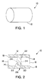
- FIG. 1 Representatively illustrated in FIG. 1 is a method of manufacturing a sensor 10 which embodies principles of the present invention.
- directional terms such as “above”, “below”, “upper”, “lower”, etc., are used for convenience in referring to the accompanying drawings. Additionally, it is to be understood that the various embodiments of the present invention described herein may be utilized in various orientations, such as inclined, inverted, horizontal, vertical, etc., without departing from the principles of the present invention.
- the method begins with a single piezoelectric crystal 12.
- the crystal 12 may be cylindrical in shape as shown in FIG. 1, or other shapes may be utilized, if desired.
- the crystal 12 is preferably an AT cut quartz crystal, of the type well known to those skilled in the art.
- FIG. 2 depicts the bores 14 as being symmetrical and identically formed into the crystal 12, but this is not necessary in keeping with the principles of the present invention.
- the bores 14 Prior to etching the bores 14 into the crystal 12, the bores may be rough machined, for example, by single point diamond machining or ultrasonic milling. Additionally, even though the high aspect ratio etching significantly reduces the possibility of imperfections being formed in the bores 14 as compared to conventional grinding techniques, the etching step may be followed by ion milling to even further reduce the possibility of imperfections.
- an active resonator element 20 is defined between the bores.
- the resonator element 20 may have electrodes (not shown) attached thereto using conventional techniques in order to induce vibration of the element. With the resonator element 20 so formed between the bores 14 and electrodes attached thereto as desired, a sensor 26 is thereby produced by the method 10 from the crystal 12.
- the resonator element 20 may be isolated from fluids surrounding the sensor 26 by attaching closures or end caps to the ends 16, using techniques well known to those skilled in the art, thereby constructing a sensor assembly.
- the resonator element 20 may have flat opposing sides 22 facing the respective bores 14 as depicted by the solid lines in FIG. 2.
- the resonator element 20 may have convex opposing sides 24 as depicted by the dashed lines in FIG. 2.
- the sensor 26 is shown in FIG. 3 from an end view in which it may be seen that openings 28 are formed through the resonator element 20 on opposing sides of an axis of the crystal 12.
- the openings 28 are formed on opposing sides of the x-axis of the resonator element 20.
- this technique enhances the sensitivity of the resonator element 20 to changes in stress applied uniformly around the crystal 12.
- the openings 28 are generally arc-shaped as depicted in FIG. 3 and extend up to an angle A from the x-axis on either side thereof.
- the angle A is approximately 30 degrees, although other angles may be utilized without departing from the principles of the present invention.
- the openings 28 define attachments 30 by which the resonator element 20 is attached to an outer peripheral portion 32 of the crystal 12. These attachments 30 are aligned with the x-axis of the crystal 12.
- FIG. 4 an alternative construction of a sensor 40 embodying principles of the present invention is representatively illustrated. Elements shown in FIG. 4 which are similar to those previously described are indicated using the same reference numbers.
- the sensor 40 includes a resonator element 20 having openings 28 formed therethrough.
- the x-axis of the AT cut quartz crystal of which the sensor 40 is formed extends perpendicular to the plane of the drawing page and so is represented in FIG. 4 as a dot 42.
- the resonator element 20 is attached to a peripheral portion 44 of the sensor 40 with attachments (not visible in FIG. 4) aligned with the x-axis, similar to the sensor 26.
- the senor 40 is constructed as a generally disc-shaped piece, which then has end caps or closures 46 attached to either side thereof to form a sensor assembly 48.
- the end caps 46 isolate the resonator element 20 from fluid surrounding the sensor assembly 48 and may be attached, for example, using glass.
- FIG. 5 an alternative construction of a sensor 50 embodying principles of the present invention is representatively illustrated. Elements shown in FIG. 5 which are similar to those previously described are indicated using the same reference numbers.
- the sensor 50 is similar to the sensor 26 as shown in FIG. 2. As with the sensor 26, the sensor 50 is made from a single piezoelectric crystal 52 in which the bores 14 have been formed from opposite ends of the crystal, thereby defining the resonator element 20 therebetween. However, the sensor 50 differs in at least one significant respect in that the crystal 52 has an elliptical cross-section.
- the sensor 50 is shown in FIG. 5 from an end view thereof, in which it will be readily appreciated that the crystal 52 has an elliptical cross-section.
- the AT cut quartz crystal 52 is provided so that the x-axis thereof is aligned with a minor axis of the crystal's elliptical cross-section.
- the minor axis of the crystal's elliptical cross-section coincides with the x-axis of the crystal.
Landscapes
- Chemical & Material Sciences (AREA)
- Engineering & Computer Science (AREA)
- Ceramic Engineering (AREA)
- Physics & Mathematics (AREA)
- General Physics & Mathematics (AREA)
- Measuring Fluid Pressure (AREA)
- Piezo-Electric Or Mechanical Vibrators, Or Delay Or Filter Circuits (AREA)
Abstract
Description
Claims (10)
- A method of producing a sensor (26,40,50), comprising the steps of: masking an outer peripheral portion of opposite crystal ends (16) of a single AT cut quartz crystal (12); and etching a bore (14) into each crystal end (14), thereby forming an active resonator element (20) between the bores (14) without grinding the crystal (12).
- A method according to Claim 1, wherein the crystal (12) is cylindrical.
- A method according to Claim 1, wherein the crystal (12) has an elliptical cross-section.
- A method according to Claim 3, wherein a minor axis of the elliptical cross-section is aligned with an x-axis of the crystal (12).
- A pressure sensor (26,40,50), comprising: a single piece of AT cut quartz crystal (12) having opposite ends (16) and a bore (14) extending into each end (16), thereby defining an active resonator element (20) between the bores (14), a pair of openings (28) being formed through the resonator element (20), so that the resonator element (20) remains attached to a peripheral (32,44) portion of the crystal (12) by two attachments (30) aligned with an x-axis of the crystal.
- A sensor (26,40,50) according to Claim 5, wherein each of the attachments extends approximately thirty degrees to either side of the x-axis.
- A sensor (26,40) according to Claim 5 or 6, wherein the crystal is cylindrical.
- A pressure sensor assembly, comprising: a sensor (40) formed from a single piece of AT cut quartz crystal (12), the sensor (40) having two openings (28) formed therethrough defining an active resonator element (20) and two attachments (30) securing the resonator element (20) to a peripheral portion (44) of the sensor (40), the attachments (30) being aligned with an x-axis of the sensor (40); and at least one closure (46) isolating the resonator element (20) from fluid surrounding the sensor assembly.
- A pressure sensor assembly according to Claim 8, wherein opposite sides of the resonator element (20) are flat.
- A pressure sensor assembly according to Claim 8, wherein opposite sides of the resonator element (20) are convex.
Applications Claiming Priority (2)
| Application Number | Priority Date | Filing Date | Title |
|---|---|---|---|
| US38965499A | 1999-09-02 | 1999-09-02 | |
| US389654 | 1999-09-02 |
Publications (2)
| Publication Number | Publication Date |
|---|---|
| EP1085309A2 true EP1085309A2 (en) | 2001-03-21 |
| EP1085309A3 EP1085309A3 (en) | 2001-06-13 |
Family
ID=23539151
Family Applications (1)
| Application Number | Title | Priority Date | Filing Date |
|---|---|---|---|
| EP00307469A Withdrawn EP1085309A3 (en) | 1999-09-02 | 2000-08-31 | Vibrating quartz diaphragm pressure sensor |
Country Status (3)
| Country | Link |
|---|---|
| EP (1) | EP1085309A3 (en) |
| CA (1) | CA2317229A1 (en) |
| NO (1) | NO20004342L (en) |
Cited By (2)
| Publication number | Priority date | Publication date | Assignee | Title |
|---|---|---|---|---|
| CN108267247A (en) * | 2018-04-24 | 2018-07-10 | 成都奥森泰科技有限公司 | A kind of cylindrical structure integral type resonance pressure sensor |
| CN108332886A (en) * | 2018-04-24 | 2018-07-27 | 成都奥森泰科技有限公司 | A kind of integral type quartz resonance pressure sensor structure |
Family Cites Families (5)
| Publication number | Priority date | Publication date | Assignee | Title |
|---|---|---|---|---|
| US3561832A (en) * | 1969-12-05 | 1971-02-09 | Hewlett Packard Co | Quartz resonator pressure transducer |
| FR2531532A1 (en) * | 1982-08-05 | 1984-02-10 | Flopetrol | PIEZOELECTRIC SENSOR, IN PARTICULAR FOR MEASURING PRESSURES |
| US4550610A (en) * | 1983-11-28 | 1985-11-05 | Quartztronics, Inc. | Resonator pressure transducer |
| GB2235533B (en) * | 1989-08-11 | 1994-02-09 | Stc Plc | Piezoelectric sensor device |
| US5221873A (en) * | 1992-01-21 | 1993-06-22 | Halliburton Services | Pressure transducer with quartz crystal of singly rotated cut for increased pressure and temperature operating range |
-
2000
- 2000-08-31 EP EP00307469A patent/EP1085309A3/en not_active Withdrawn
- 2000-09-01 CA CA 2317229 patent/CA2317229A1/en not_active Abandoned
- 2000-09-01 NO NO20004342A patent/NO20004342L/en not_active Application Discontinuation
Cited By (2)
| Publication number | Priority date | Publication date | Assignee | Title |
|---|---|---|---|---|
| CN108267247A (en) * | 2018-04-24 | 2018-07-10 | 成都奥森泰科技有限公司 | A kind of cylindrical structure integral type resonance pressure sensor |
| CN108332886A (en) * | 2018-04-24 | 2018-07-27 | 成都奥森泰科技有限公司 | A kind of integral type quartz resonance pressure sensor structure |
Also Published As
| Publication number | Publication date |
|---|---|
| NO20004342D0 (en) | 2000-09-01 |
| CA2317229A1 (en) | 2001-03-02 |
| EP1085309A3 (en) | 2001-06-13 |
| NO20004342L (en) | 2001-03-05 |
Similar Documents
| Publication | Publication Date | Title |
|---|---|---|
| US4547691A (en) | Piezoelectric pressure and/or temperature transducer | |
| EP0604519B1 (en) | Micromechanical tuning fork angular rate sensor | |
| US8294332B2 (en) | Pressure transducer | |
| US4694703A (en) | Circumferentially oriented flexure suspension | |
| US20010039837A1 (en) | Pressure detecting apparatus with metallic diaphragm | |
| US4562375A (en) | Piezoelectric transducer, notably for pressure measurement | |
| US10048146B2 (en) | Thickness shear mode resonator sensors and methods of forming a plurality of resonator sensors | |
| US20040231422A1 (en) | Acceleration sensor and manufacturing method for the same | |
| US8635909B2 (en) | Vibrating micromechanical sensor of angular velocity | |
| EP0552884B1 (en) | Pressure transducer with quartz crystal | |
| US20150059483A1 (en) | Sensors for measuring at least one of pressure and temperature, and related assemblies and methods | |
| CA2233374C (en) | Monolithic accelerometric transducer | |
| CA2317229A1 (en) | Quartz pressure sensor | |
| US7404325B2 (en) | Micro-machined vibrating structure and associated micro-gyroscope | |
| US7296467B2 (en) | Angular velocity sensor | |
| US6455985B1 (en) | Pressure and temperature transducer | |
| US6145383A (en) | Pressure sensor | |
| CN111051814B (en) | High Quality Factor MEMS Silicon Hinge and Slot Notch Resonators for Vibratory Gyroscopes | |
| WO1991003716A1 (en) | Tuning fork force sensor | |
| JPH03282373A (en) | Structure of acceleration sensor and production thereof | |
| WO2000014500A1 (en) | Pressure and temperature transducer | |
| JPH06300774A (en) | Acceleration sensor | |
| JPH07202220A (en) | Semiconductor acceleration sensor | |
| Das et al. | Analytical model of MEMS-based piezoresistive pressure sensor using Si3N4 diaphragm | |
| JPH0854414A (en) | Semiconductor acceleration sensor and manufacturing method thereof |
Legal Events
| Date | Code | Title | Description |
|---|---|---|---|
| PUAI | Public reference made under article 153(3) epc to a published international application that has entered the european phase |
Free format text: ORIGINAL CODE: 0009012 |
|
| AK | Designated contracting states |
Kind code of ref document: A2 Designated state(s): CH DE FR GB LI NL |
|
| AX | Request for extension of the european patent |
Free format text: AL;LT;LV;MK;RO;SI |
|
| PUAL | Search report despatched |
Free format text: ORIGINAL CODE: 0009013 |
|
| AK | Designated contracting states |
Kind code of ref document: A3 Designated state(s): AT BE CH CY DE DK ES FI FR GB GR IE IT LI LU MC NL PT SE |
|
| AX | Request for extension of the european patent |
Free format text: AL;LT;LV;MK;RO;SI |
|
| 17P | Request for examination filed |
Effective date: 20011101 |
|
| AKX | Designation fees paid |
Free format text: CH DE FR GB LI NL |
|
| 17Q | First examination report despatched |
Effective date: 20020513 |
|
| STAA | Information on the status of an ep patent application or granted ep patent |
Free format text: STATUS: THE APPLICATION IS DEEMED TO BE WITHDRAWN |
|
| 18D | Application deemed to be withdrawn |
Effective date: 20020924 |