EP1085305A2 - Method/system for resetting the value of a control parameter indicative of gross combined weight of vehicles to a default value thereof - Google Patents
Method/system for resetting the value of a control parameter indicative of gross combined weight of vehicles to a default value thereof Download PDFInfo
- Publication number
- EP1085305A2 EP1085305A2 EP00119881A EP00119881A EP1085305A2 EP 1085305 A2 EP1085305 A2 EP 1085305A2 EP 00119881 A EP00119881 A EP 00119881A EP 00119881 A EP00119881 A EP 00119881A EP 1085305 A2 EP1085305 A2 EP 1085305A2
- Authority
- EP
- European Patent Office
- Prior art keywords
- value
- control parameter
- gcw
- parameter value
- vehicle
- Prior art date
- Legal status (The legal status is an assumption and is not a legal conclusion. Google has not performed a legal analysis and makes no representation as to the accuracy of the status listed.)
- Withdrawn
Links
Images


Classifications
-
- G—PHYSICS
- G01—MEASURING; TESTING
- G01G—WEIGHING
- G01G19/00—Weighing apparatus or methods adapted for special purposes not provided for in the preceding groups
- G01G19/08—Weighing apparatus or methods adapted for special purposes not provided for in the preceding groups for incorporation in vehicles
- G01G19/086—Weighing apparatus or methods adapted for special purposes not provided for in the preceding groups for incorporation in vehicles wherein the vehicle mass is dynamically estimated
-
- F—MECHANICAL ENGINEERING; LIGHTING; HEATING; WEAPONS; BLASTING
- F16—ENGINEERING ELEMENTS AND UNITS; GENERAL MEASURES FOR PRODUCING AND MAINTAINING EFFECTIVE FUNCTIONING OF MACHINES OR INSTALLATIONS; THERMAL INSULATION IN GENERAL
- F16H—GEARING
- F16H59/00—Control inputs to control units of change-speed- or reversing-gearings for conveying rotary motion
- F16H59/50—Inputs being a function of the status of the machine, e.g. position of doors or safety belts
- F16H59/52—Inputs being a function of the status of the machine, e.g. position of doors or safety belts dependent on the weight of the machine, e.g. change in weight resulting from passengers boarding a bus
-
- F—MECHANICAL ENGINEERING; LIGHTING; HEATING; WEAPONS; BLASTING
- F16—ENGINEERING ELEMENTS AND UNITS; GENERAL MEASURES FOR PRODUCING AND MAINTAINING EFFECTIVE FUNCTIONING OF MACHINES OR INSTALLATIONS; THERMAL INSULATION IN GENERAL
- F16H—GEARING
- F16H61/00—Control functions within control units of change-speed- or reversing-gearings for conveying rotary motion ; Control of exclusively fluid gearing, friction gearing, gearings with endless flexible members or other particular types of gearing
- F16H61/16—Inhibiting or initiating shift during unfavourable conditions , e.g. preventing forward-reverse shift at high vehicle speed, preventing engine overspeed
-
- Y—GENERAL TAGGING OF NEW TECHNOLOGICAL DEVELOPMENTS; GENERAL TAGGING OF CROSS-SECTIONAL TECHNOLOGIES SPANNING OVER SEVERAL SECTIONS OF THE IPC; TECHNICAL SUBJECTS COVERED BY FORMER USPC CROSS-REFERENCE ART COLLECTIONS [XRACs] AND DIGESTS
- Y10—TECHNICAL SUBJECTS COVERED BY FORMER USPC
- Y10S—TECHNICAL SUBJECTS COVERED BY FORMER USPC CROSS-REFERENCE ART COLLECTIONS [XRACs] AND DIGESTS
- Y10S477/00—Interrelated power delivery controls, including engine control
- Y10S477/90—Control signal is vehicle weight
Definitions
- This invention relates to systems/methods for determining a value indicative of vehicular gross combined weight (GCW) in vehicles equipped with automated transmission systems or manual transmission systems and electronic data links.
- the present invention relates to a system/method for determining the GCW of vehicles, such as heavy-duty trucks or coaches equipped with an electronic databus carrying engine torque and other information, such as a databus conforming to the CAN, SAE J1922 and/or SAE J1939 protocol, wherein the control parameter indicative of GCW is a filtered, averaged value, often an average of 500 or more individual determination iterations, to minimize the effects of driveline torsionals, noise and the like.
- the control parameter indicative of GCW is a filtered, averaged value, often an average of 500 or more individual determination iterations, to minimize the effects of driveline torsionals, noise and the like.
- the present invention relates to a GCW value determination method/system wherein the GCW control parameter is a filtered, averaged value and wherein the GCW control parameter value is reset to a default value thereof upon sensing that the current highly filtered value for GCW may be inaccurate.
- vehicle GCW may vary in a range of from about 10,000 pounds up to about 80,000 pounds or more, depending upon vehicle type and load, It is highly desirable to inform the vehicle operator of at least approximate current GCW and/or to provide this information to vehicle systems such as, e.g., an automated transmission system, a fleet management system, a variable suspension system, an onboard central tire inflation system (CTIS), an antilock brake system (ABS) or the like.
- vehicle systems such as, e.g., an automated transmission system, a fleet management system, a variable suspension system, an onboard central tire inflation system (CTIS), an antilock brake system (ABS) or the like.
- CIS central tire inflation system
- ABS antilock brake system
- GCW (T 1 - T 2 ) ⁇ ((A 1 - A 2 ) ⁇ C)
- GCW is, preferably, determined during or immediately after completion of an upshift and the control parameter GCW CP is a running, filtered average of many individual iterations of GCW determination. While the above-described methods/systems are very effective, they are not totally satisfactory as, in certain circumstances, they may not be as responsive as desired to situations wherein vehicles have stopped to change their loading, such as, for example, by adding or unloading cargo, connecting or disconnecting a semitrailer taking on or discharging coach passengers, or the like.
- a system for resetting the highly filtered value of GCW upon sensing conditions indicative of (i) the vehicle being at rest and/or the highly filtered value (GCW CP ) differing from a less-filtered test value (GCW TEST ) by greater than a predetermined value may be seen by reference to U.S. Pat. No. 5,491,630, the disclosure of which is incorporated herein by reference.
- the drawbacks of the prior art are minimized or eliminated by the provision of a system/method for determination of vehicular GCW wherein the value of the control parameter outputted by the system as indicative of vehicular gross combined weight (GCW CP ) is a relatively highly filtered, averaged value of a large number of previous (GCW i ) determination iterations, and said value is reset to a preselected/predetermined default value upon the occurrence of conditions associated with probable vehicle change of load.
- GCW CP vehicular gross combined weight
- a control parameter GCW CP indicative of vehicular GCW indicative of vehicular GCW as a relatively highly filtered, averaged value of previous GCW determination iterations by (1) selecting/ determining a default value for said value, (2) calculating a test GCW value (GCW TEST ) alongside the estimated GCW value (GCW CP ), the test value being much less filtered and calculated on virtually every upshift, (3) comparing the estimated value to the test value to determine if the test value is within a given percentage of the estimated value (((0.5)(GCW CP )) ⁇ GCW TEST ⁇ ((2.0)(GCW CP )))?) and, if not, causing said value to be reset to the default value thereof.
- the default value of GCW is equal to a relatively large GCW for the vehicle.
- the default value will be selected with a view toward the system or systems using GCW as a control parameter. For example, in an automated mechanical transmission system wherein the transmission is controlled, at least in part, as a function of the value of the GCW control parameter, selecting a relatively large default value will tend to result in errors wherein shifting is somewhat aggressive, which is considered to be more desirable than errors wherein a shift expected and desired by the operator is not attempted.
- compound transmission is used to designate a change speed or change gear transmission having a multiple forward speed main transmission section and a multiple speed auxiliary transmission section connected in series whereby the selected gear reduction in the main transmission section may be compounded by further selected gear reduction in the auxiliary transmission section.
- Synchronized clutch assembly shall designate a clutch assembly utilized to nonrotatably couple a selected gear to a shaft by means of a positive clutch in which attempted engagement of said clutch is prevented until the members of the clutch are at substantially synchronous rotation.
- a relatively large capacity friction means are utilized with the clutch members and are sufficient, upon initiation of a clutch engagement, to cause the clutch members and all members rotating therewith to rotate at substantially synchronous speed.
- upshift shall mean the shifting from a lower speed gear ratio into a higher speed gear ratio.
- the vehicular GCW determination method/system of the present invention is disclosed as associated with a vehicular drivetrain including an automated mechanical transmission and an electronically controlled engine having a CAN, SAE J1922 or SAE J1939 type data link. It is understood that the vehicular GCW determination system/method of the present invention also may be advantageously utilized with other types of vehicular drivetrain systems.
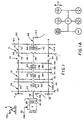
- Compound transmission 10 comprises a multiple speed main transmission section 12 connected in series with a range type auxiliary section 14.
- Transmission 10 is housed within a housing H and includes an input shaft 16 driven by a prime mover such as diesel engine E through a selectively disengaged, normally engaged friction master clutch C having an input or driving portion 18 drivingly connected to the engine crankshaft 20 and a driven portion 22 rotatably fixed to the transmission input shaft 16.
- a prime mover such as diesel engine E
- a selectively disengaged, normally engaged friction master clutch C having an input or driving portion 18 drivingly connected to the engine crankshaft 20 and a driven portion 22 rotatably fixed to the transmission input shaft 16.
- the engine E is fuel throttle controlled, preferably electronically, and is connected to an electronic data link DL of the type defined in SAE J1922 and/or SAE J1939 protocol, and the master clutch C may be manually controlled by a clutch pedal (not shown) or the like.
- Master clutch C if used in fully automatic transmission systems, may be automatically controlled, see U.S. Pats. No. 4,081,065 and 4,361,060, the disclosures of which are incorporated herein by reference.
- fuel modulation (as disclosed in U.S. Pat. No. 4,850,236) may be utilized for shifting without releasing the master clutch.
- electronically controlled engine E will be provided with its own electronic control unit ECU E .
- An input shaft brake (not shown) may be provided to provide quicker manual upshifting as is well known in the prior art. It is understood that a data link or databus, DL, complying with SAE J1939 protocol, or similar protocol, will carry information indicative of engine torque, engine speed and transmission output shaft speed.
- the input shaft 16 carries an input gear 24 for simultaneously driving a plurality of substantially identical countershaft assemblies 26 and 26A at substantially identical rotational speeds.
- the two substantially identical countershaft assemblies are provided on diametrically opposite sides of mainshaft 28 which is generally coaxially aligned with the input shaft 16.
- Each of the countershaft assemblies comprises a countershaft 30 supported by bearings 32 and 34 in housing H, only a portion of which is schematically illustrated.
- Each of the countershafts is provided with an identical grouping of countershaft gears 38, 40, 42, 44, 46 and 48, fixed for rotation therewith.
- a plurality of mainshaft gears 50, 52, 54, 56 and 58 surround the mainshaft 28 and are selectively clutchable, one at a time, to the mainshaft 28 for rotation therewith by sliding clutch collars 60, 62 and 64 as is well known in the prior art.
- Clutch collar 60 may also be utilized to clutch input gear 24 to mainshaft 28 to provide a direct drive relationship between input shaft 16 and mainshaft 28.
- clutch collars 60, 62 and 64 are axially positioned by means of shift forks associated with the shift bar housing assembly 70, as well known in the prior art.
- Clutch collars 60, 62 and 64 may be of the well known nonsynchronized double acting jaw clutch type. As is well known, the clutch collars are shifted forwardly and rearwardly by shift forks controlled by transmission actuator 120 (see Fig. 2) of the type illustrated in U.S. Pats. No. 4,873,881 and 4,936,156, the disclosures of which are incorporated herein by reference.
- Mainshaft gear 58 is the reverse gear and is in continuous meshing engagement with countershaft gears 48 by means of conventional intermediate idler gears (not shown). It should also be noted that while main transmission section 12 does provide five selectable forward speed ratios, the lowest forward speed ratio, namely that provided by drivingly connecting mainshaft drive gear 56 to mainshaft 28, is often of such a high gear reduction it has to be considered a low or "creeper" gear which is utilized only for starting of a vehicle under severe conditions and is not usually utilized in the high transmission range. Accordingly, while main transmission section 12 does provide five forward speeds, it is usually referred to as a "four plus one" main section as only four of the forward speeds are compounded by the auxiliary range transmission section 14 utilized therewith.
- Jaw clutches 60, 62, and 64 are three-position clutches in that they may be positioned in the centered, nonengaged position as illustrated, or in a fully rightwardly engaged or fully leftwardly engaged position by means of actuator 70. As is well known, only one of the clutches 60, 62 and 64 is engageable at a given time and main section interlock means (not shown) may be provided to lock the other clutches in the neutral condition.
- Auxiliary transmission range section 14 includes two substantially identical auxiliary countershaft assemblies 74 and 74A, each comprising an auxiliary countershaft 76 supported by bearings 78 and 80 in housing H and carrying two auxiliary section countershaft gears 82 and 84 for rotation therewith.
- Auxiliary countershaft gears 82 are constantly meshed with and support range/output gear 86 while auxiliary section countershaft gears 84 are constantly meshed with output gear 88.
- a two-position synchronized jaw clutch assembly 92 which is axially positioned by means of a shift fork (not shown) and the range section shifting actuator assembly 96, is provided for clutching either gear 86 to output shaft 90 for direct or high range operation or gear 88 to output shaft 90 for low range operation of the compound transmission 10.
- the "shift pattern" for compound range type transmission 10 is schematically illustrated in Figure A. Actuator 120, preferably, also will control the range section.
- an input shaft speed sensor 98, an engine speed sensor 99 and/or an output shaft speed sensor 100 may be utilized.
- a sensor 102 for sensing the rotational speed of auxiliary section countershaft gear 82 may be utilized.
- the rotational speed of gear 82 is, of course, a known function of the rotational speed of mainshaft 28 and, if clutch 92 is engaged in a known position, a function of the rotational speed of output shaft 90.
- Engine speed and/or output shaft speed information preferably is carried on the data link DL. As is well known (see above-mentioned U.S. Pat. No.
- the signals (OS) from speed sensor 100 or other sensors may be differentiated with respect to time to provide signals (dOS/dt) having a value indicative of vehicle acceleration and the like.
- the ECU 106 will, preferably, include logic elements or rules for differentiating various input signals with respect to time.
- the ECU 106 may be of the type illustrated in U.S. Patent No. 4,595,986, the disclosure of which is incorporated herein by reference.
- the ECU is effective to process the inputs 122 in accordance with predetermined logic rules to issue command output signals 124 to the engine ECU (ECU E ) and to actuator 120 and/or to a display unit and/or to other systems, such as an ABS system or a CTIS system or the like.
- a separate ECU for GCW determination may be provided or the logic rules for determining vehicle GCW may be in the engine ECU (ECU E ) or another system ECU.
- Input shaft speed (IS) may be taken as equal to engine speed (ES), available on datalink DL, when clutch C is fully engaged.
- a system/method for determining vehicular GCW using existing information from an electronic engine (SAE J1922 or J1939 protocol) data link and/or using information from various sensors such as, for example, signals indicative of engine/drivewheel torque and a signal indicative of vehicle or output shaft speed.
- SAE J1922 or J1939 protocol electronic engine
- T 1 - T 2 C ⁇ W ⁇ (A 1 - A 2 )
- GCW CP equaling an average
- a new GCW i is calculated about every 40 milliseconds after t 2 until about four seconds after t 1 .
- the GCW i values are then summed and averaged.
- the filtering/averaging technique adjusts for errors in each individual iteration due to torsionals, noise and the like which may render individual iterations of GCW relatively inaccurate.
- the counter reaches 1,000, the sum is divided in half, the counter set to 500, and the averaging continues. This will provide a filtering of the GCW value.
- GCW CP [GCW i +(499*GCW CP )] 500
- values of A 2 ... i and T 2 ... i will not be sensed until certain conditions are met, assuring that the subsequent values are different enough in magnitude from the time t 1 values to provide valid calculations for GCW.
- the drivewheel torque at time t i the engine torque is sensed, preferably from the electronic data link DL, and used to derive the drivewheel torque in a known manner.
- torque at the drivewheels may be determined from the following:
- T FW T EG - T BEF - T ACCES - T ACCEL
- control parameter GCW CP indicative of vehicular GCW is useful in determining feasibility of shifts in an automated transmission system, see U.S. Pats. No. 5,272,939; 5,241,476 and 5,172,609, the disclosures of which are incorporated herein by reference, as welt as in fleet management systems, antilock brake systems (ABS), central tire inflation systems (CTIS), active suspension systems and the like.
- the method/system in certain circumstances, may not be as responsive to relatively large changes in vehicle loading as is desirable. Examples of relatively large changes in vehicle loading include loading or unloading (dumping) cargo, adding or dropping a trailer or semi-trailer, embarking or disembarking a group of coach passengers and the like.
- This method does not correct very quickly; however, the GCW if the true vehicle GCW changes suddenly a large amount. Furthermore, the above GCW estimate algorithm has certain conditions under which a given upshift may be used to calculate GCW (i.e., shift duration must be long enough, cannot be on a steep grade/load, etc.). Because of this, if the true GCW changes drastically enough and then the vehicle shift algorithm (using a wrong GCW estimate) alters its shift behavior such that it "thinks" it is on a steep grade (due to the wrong GCW), it may make only short shifts (a 16- or 18-speed AutoShift) forever after and never calculate GCW again.
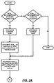
- the above problems are minimized by calculating a "test GCW" alongside the regular GCW.
- This "test GCW” gets calculated during nearly every upshift (some exceptions may apply, i.e., not short shifts in high range, etc.), regardless of shift duration or indicated grade/load.
- the "test GCW” is made up of an average of many estimates -- just like the regular GCW -- but the "test GCW sum” and the “test GCW sum count” get divided by two when the "test GCW sum count” reaches a much smaller value (such as 150). This provides a much lighter averaging filter for the "test GCW.”
- test GCW is different than the "regular GCW” by a factor of two either way (test GCW is twice as large as GCW CP or test GCW is half of GCW CP ), both the GCW CP and the test GCW get "reset.”
- both numbers get initialized to a value (usually a very large value)
- the GCW sum counters (test and regular) get set back to one
- the GCW sums (test and regular) get set to the initialized GCW value (usually very large).
Landscapes
- Engineering & Computer Science (AREA)
- General Engineering & Computer Science (AREA)
- Mechanical Engineering (AREA)
- Physics & Mathematics (AREA)
- General Physics & Mathematics (AREA)
- Control Of Transmission Device (AREA)
Abstract
Description
- Ti =
- Wheel torque at time ti ;
- Ai =
- Vehicle acceleration at time ti ; and
- C =
- Wheel rolling radius ÷ gravity constant.
- Ti
- = Wheel torque at time ti ;
- C
- = Rolling radius/gravity constant;
- W
- = Gross combination weight; and
- Ai
- = Vehicle acceleration at time ti .

- Torque at wheels =
- (engine torque) * (gear ratio) * (axle ratio) * (drivetrain efficiency);
- where engine torque =
- [(percent engine torque) * (peak engine torque)] - [(torque to drive vehicle accessories) + (torque to accelerate engine)].
- TFW =
- engine flywheel torque;
- TEG =
- gross engine torque;
- TBEF =
- base engine friction torque (includes the torque to overcome engine internal friction and the torque to rotate the engine manufacturer-installed accessories (i.e., water pump, oil pump, etc.)):
- TACCES =
- accessory torque (torque to operate vehicle accessories, such as air-conditioning, fans, lights, etc.); and
- TACCEL =
- torque to accelerate engine, calculated from engine acceleration or deceleration and moment of inertia (I) of engine.
Claims (10)
- A control system for an automated vehicle system on a vehicle, said vehicle system including a controller for controlling said vehicle system as a function of input signals and predetermined logic rules, said control system comprising:means for continuously determining current vehicular gross combined weight upon the occurrence of determination enabling conditions comprising:means for determining a revised control parameter value (GCWCP) indicative of current gross combined weight as a filtered average of a current and a predetermined first plurality of previous determinations of current vehicular gross combined weight;means for determining a revised test value (GCWTEST) of current vehicle gross combined weight as a filtered average of a current and a predetermined second plurality of previous determinations of current vehicular gross combined weight, said first plurality at least twice as great as said second plurality of determinations;means for comparing said control parameter value to said test value;means for setting said control parameter value to a predetermined default value independent of said control parameter value or said test value if said control parameter value is less than a first percentage of saia test value or greater than a second percentage of said test value; andmeans for causing said vehicle system to be controlled as a function of said control parameter value.
- The control system of claim 1 wherein said automated system is an automated mechanical transmission system and said enabling conditions comprise completion of an upshift within a predetermined period of time.
- The system of claim 1 wherein said first percentage is about 50% and said second percentage is about 200%.
- The system of claim 1 wherein said revised control parameter value is determined only if engine braking is not active and said revised test value is determined, regardless of condition of the engine brakes.
- The system of claim 2 wherein said revised control parameter value is determined only if engine braking is not active and said revised test value is determined, regardless of condition of the engine brakes.
- A method for controlling an automated vehicle system on a vehicle, said vehicle system including a controller for controlling said vehicle system as a function of input signals and predetermined logic rules, said method comprising the steps of:continuously determining current vehicular gross combined weight upon the occurrence of determination enabling conditions comprising:determining a revised control parameter value (GCWCP) indicative of current gross combined weight as a filtered average of a current and a predetermined first plurality of previous determinations of current vehicular gross combined weight;determining a revised test value (GCWTEST) of current vehicle gross combined weight as a filtered average of a current and a predetermined second plurality of previous determinations of current vehicular gross combined weight, said first plurality at least twice as great as said second plurality of determinations;comparing said control parameter value to said test value;setting said control parameter value to a predetermined default value independent of said control parameter value or said test value if said control parameter value is less than a first percentage of saia test value or greater than a second percentage of said test value; andcausing said vehicle system to be controlled as a function of said control parameter value.
- The method of claim 6 wherein said automated system is an automated mechanical transmission system and said enabling conditions comprise completion of an upshift within a predetermined period of time.
- The method of claim 6 wherein said first percentage is about 50% and said second percentage is about 200%.
- The method of claim 6 wherein said revised control parameter value is determined only if engine braking is not active and said revised test value is determined, regardless of condition of the engine brakes.
- The method of claim 7 wherein said revised control parameter value is determined only if engine braking is not active and said revised test value is determined, regardless of condition of the engine brakes.
Applications Claiming Priority (2)
| Application Number | Priority Date | Filing Date | Title |
|---|---|---|---|
| US397328 | 1999-09-16 | ||
| US09/397,328 US6205389B1 (en) | 1999-09-16 | 1999-09-16 | Method/system for resetting the value of a control parameter indicative of gross combine weight of vehicles to a default value thereof |
Publications (2)
| Publication Number | Publication Date |
|---|---|
| EP1085305A2 true EP1085305A2 (en) | 2001-03-21 |
| EP1085305A3 EP1085305A3 (en) | 2002-01-30 |
Family
ID=23570770
Family Applications (1)
| Application Number | Title | Priority Date | Filing Date |
|---|---|---|---|
| EP00119881A Withdrawn EP1085305A3 (en) | 1999-09-16 | 2000-09-13 | Method/system for resetting the value of a control parameter indicative of gross combined weight of vehicles to a default value thereof |
Country Status (2)
| Country | Link |
|---|---|
| US (1) | US6205389B1 (en) |
| EP (1) | EP1085305A3 (en) |
Families Citing this family (7)
| Publication number | Priority date | Publication date | Assignee | Title |
|---|---|---|---|---|
| US6394931B1 (en) * | 1999-07-19 | 2002-05-28 | Eaton Corporation | Starting and driveline shock protection control method and system |
| GB0015465D0 (en) * | 2000-06-26 | 2000-08-16 | New Holland Uk Ltd | A method and apparatus for controlling a tractor/implement combination |
| US6526816B2 (en) * | 2000-12-13 | 2003-03-04 | Eaton Corporation | Transmission gear life monitor system |
| EP1355209A1 (en) | 2002-04-18 | 2003-10-22 | Ford Global Technologies, LLC | Vehicle control system |
| US6984192B2 (en) * | 2002-11-01 | 2006-01-10 | Eaton Corporation | Throttle ramp rate control system for a vehicle |
| JP4839647B2 (en) * | 2005-03-22 | 2011-12-21 | 日産自動車株式会社 | Synchronous shift control device for automatic transmission |
| US10745009B2 (en) * | 2016-12-21 | 2020-08-18 | Samsung Electronics Co., Ltd. | Electronic apparatus for determining a dangerous situation of a vehicle and method of operating the same |
Family Cites Families (7)
| Publication number | Priority date | Publication date | Assignee | Title |
|---|---|---|---|---|
| US5335566A (en) | 1992-07-06 | 1994-08-09 | Eaton Corporation | Shift control method/system |
| US5272939B1 (en) | 1992-07-06 | 1994-12-06 | Eaton Corp | Shift enable control method/system |
| US5490063A (en) | 1994-02-07 | 1996-02-06 | Eaton Corporation | Control method/system including determination of an updated value indicative of gross combination weight of vehicles |
| US5487005A (en) | 1994-02-07 | 1996-01-23 | Eaton Corporation | Method/system for determination of gross combined weight of vehicles equipped with electronic data links |
| US5582069A (en) * | 1994-05-16 | 1996-12-10 | Eaton Corporation | Engine accessory torque and engine deceleration rate determination method/system |
| US5491630A (en) | 1994-08-03 | 1996-02-13 | Eaton Corporation | Method/system for resetting the value of a control parameter indicative of gross combined weight of vehicles to a default value thereof |
| US6116105A (en) * | 1999-01-14 | 2000-09-12 | Eaton Corporation | Method/system for controlling upshifting after resetting the value of a control parameter indicative of gross combined weight of vehicles |
-
1999
- 1999-09-16 US US09/397,328 patent/US6205389B1/en not_active Expired - Lifetime
-
2000
- 2000-09-13 EP EP00119881A patent/EP1085305A3/en not_active Withdrawn
Also Published As
| Publication number | Publication date |
|---|---|
| US6205389B1 (en) | 2001-03-20 |
| EP1085305A3 (en) | 2002-01-30 |
Similar Documents
| Publication | Publication Date | Title |
|---|---|---|
| EP0695930B1 (en) | Determination of gross combined weight of vehicles equipped with electronic data links | |
| EP0666435B1 (en) | Method/system to determine gross combination weight of vehicles | |
| EP0578398B1 (en) | Shift control method/system | |
| EP0676566B1 (en) | Engine deceleration determination method/system | |
| US5620392A (en) | Engine accessory torque and engine deceleration rate linear relationship and engine rotational moment-of-inertia determination method/system | |
| EP0670440B1 (en) | Engine brake enhanced upshift control method/system | |
| EP0677684B1 (en) | Adaptive shift control method/system | |
| CA2099551C (en) | Shift enable control method/system | |
| EP0683335B1 (en) | Engine flywheel torque determination method/system | |
| EP0695931B1 (en) | Method/system for resetting the value of a control parameter indicative of gross combined weight of vehicles to a default value thereof | |
| EP1070876B1 (en) | Method/system for controlling upshift after resetting the value of a control parameter indicative of gross combined weight of vehicles | |
| US6205389B1 (en) | Method/system for resetting the value of a control parameter indicative of gross combine weight of vehicles to a default value thereof | |
| CA2274368C (en) | Method/system for resetting the value of a control parameter indicative of gross combined weight of vehicles to a default value thereof |
Legal Events
| Date | Code | Title | Description |
|---|---|---|---|
| PUAI | Public reference made under article 153(3) epc to a published international application that has entered the european phase |
Free format text: ORIGINAL CODE: 0009012 |
|
| AK | Designated contracting states |
Kind code of ref document: A2 Designated state(s): AT BE CH CY DE DK ES FI FR GB GR IE IT LI LU MC NL PT SE Kind code of ref document: A2 Designated state(s): DE FR GB IT |
|
| AX | Request for extension of the european patent |
Free format text: AL;LT;LV;MK;RO;SI |
|
| PUAL | Search report despatched |
Free format text: ORIGINAL CODE: 0009013 |
|
| AK | Designated contracting states |
Kind code of ref document: A3 Designated state(s): AT BE CH CY DE DK ES FI FR GB GR IE IT LI LU MC NL PT SE |
|
| AX | Request for extension of the european patent |
Free format text: AL;LT;LV;MK;RO;SI |
|
| RIC1 | Information provided on ipc code assigned before grant |
Free format text: 7G 01G 19/12 A, 7F 16H 59/52 B, 7F 16H 61/02 B, 7F 16H 61/16 B |
|
| 17P | Request for examination filed |
Effective date: 20020208 |
|
| AKX | Designation fees paid |
Free format text: DE FR GB IT |
|
| 17Q | First examination report despatched |
Effective date: 20050228 |
|
| STAA | Information on the status of an ep patent application or granted ep patent |
Free format text: STATUS: THE APPLICATION IS DEEMED TO BE WITHDRAWN |
|
| 18D | Application deemed to be withdrawn |
Effective date: 20050913 |