EP1085222B1 - Plain bearing and producing method thereof - Google Patents
Plain bearing and producing method thereof Download PDFInfo
- Publication number
- EP1085222B1 EP1085222B1 EP00118279A EP00118279A EP1085222B1 EP 1085222 B1 EP1085222 B1 EP 1085222B1 EP 00118279 A EP00118279 A EP 00118279A EP 00118279 A EP00118279 A EP 00118279A EP 1085222 B1 EP1085222 B1 EP 1085222B1
- Authority
- EP
- European Patent Office
- Prior art keywords
- layer
- alloy layer
- bearing alloy
- bearing
- intermediate layer
- Prior art date
- Legal status (The legal status is an assumption and is not a legal conclusion. Google has not performed a legal analysis and makes no representation as to the accuracy of the status listed.)
- Expired - Lifetime
Links
- 238000000034 method Methods 0.000 title claims description 11
- 239000001996 bearing alloy Substances 0.000 claims abstract description 76
- 238000005530 etching Methods 0.000 claims abstract description 26
- 229910052751 metal Inorganic materials 0.000 claims abstract description 17
- 239000002184 metal Substances 0.000 claims abstract description 17
- 239000007937 lozenge Substances 0.000 claims abstract description 3
- 239000000463 material Substances 0.000 claims description 11
- 230000000873 masking effect Effects 0.000 claims description 8
- 239000011248 coating agent Substances 0.000 claims description 4
- 238000000576 coating method Methods 0.000 claims description 4
- 239000000956 alloy Substances 0.000 description 7
- 229910045601 alloy Inorganic materials 0.000 description 7
- 230000000573 anti-seizure effect Effects 0.000 description 6
- 230000013011 mating Effects 0.000 description 5
- 229910020220 Pb—Sn Inorganic materials 0.000 description 4
- 239000002131 composite material Substances 0.000 description 4
- 238000000866 electrolytic etching Methods 0.000 description 4
- 238000003754 machining Methods 0.000 description 4
- 238000007649 pad printing Methods 0.000 description 4
- 238000007747 plating Methods 0.000 description 4
- 229910000881 Cu alloy Inorganic materials 0.000 description 3
- 238000005480 shot peening Methods 0.000 description 3
- 239000000126 substance Substances 0.000 description 3
- VEXZGXHMUGYJMC-UHFFFAOYSA-N Hydrochloric acid Chemical compound Cl VEXZGXHMUGYJMC-UHFFFAOYSA-N 0.000 description 2
- MHAJPDPJQMAIIY-UHFFFAOYSA-N Hydrogen peroxide Chemical compound OO MHAJPDPJQMAIIY-UHFFFAOYSA-N 0.000 description 2
- 238000005238 degreasing Methods 0.000 description 2
- 230000006866 deterioration Effects 0.000 description 2
- 238000005554 pickling Methods 0.000 description 2
- 239000007779 soft material Substances 0.000 description 2
- XLYOFNOQVPJJNP-UHFFFAOYSA-N water Substances O XLYOFNOQVPJJNP-UHFFFAOYSA-N 0.000 description 2
- 229910000838 Al alloy Inorganic materials 0.000 description 1
- GRYLNZFGIOXLOG-UHFFFAOYSA-N Nitric acid Chemical compound O[N+]([O-])=O GRYLNZFGIOXLOG-UHFFFAOYSA-N 0.000 description 1
- ATJFFYVFTNAWJD-UHFFFAOYSA-N Tin Chemical compound [Sn] ATJFFYVFTNAWJD-UHFFFAOYSA-N 0.000 description 1
- 229910052782 aluminium Inorganic materials 0.000 description 1
- XAGFODPZIPBFFR-UHFFFAOYSA-N aluminium Chemical compound [Al] XAGFODPZIPBFFR-UHFFFAOYSA-N 0.000 description 1
- 230000001458 anti-acid effect Effects 0.000 description 1
- 239000000919 ceramic Substances 0.000 description 1
- 229910052804 chromium Inorganic materials 0.000 description 1
- 238000004140 cleaning Methods 0.000 description 1
- 239000013078 crystal Substances 0.000 description 1
- 238000009792 diffusion process Methods 0.000 description 1
- 230000001747 exhibiting effect Effects 0.000 description 1
- 239000012467 final product Substances 0.000 description 1
- 229910052742 iron Inorganic materials 0.000 description 1
- 239000000314 lubricant Substances 0.000 description 1
- 229910017604 nitric acid Inorganic materials 0.000 description 1
- 239000002245 particle Substances 0.000 description 1
- 229920002120 photoresistant polymer Polymers 0.000 description 1
- 239000011347 resin Substances 0.000 description 1
- 229920005989 resin Polymers 0.000 description 1
- 238000007650 screen-printing Methods 0.000 description 1
- 229910052709 silver Inorganic materials 0.000 description 1
- 238000005482 strain hardening Methods 0.000 description 1
Images

Classifications
-
- F—MECHANICAL ENGINEERING; LIGHTING; HEATING; WEAPONS; BLASTING
- F16—ENGINEERING ELEMENTS AND UNITS; GENERAL MEASURES FOR PRODUCING AND MAINTAINING EFFECTIVE FUNCTIONING OF MACHINES OR INSTALLATIONS; THERMAL INSULATION IN GENERAL
- F16C—SHAFTS; FLEXIBLE SHAFTS; ELEMENTS OR CRANKSHAFT MECHANISMS; ROTARY BODIES OTHER THAN GEARING ELEMENTS; BEARINGS
- F16C33/00—Parts of bearings; Special methods for making bearings or parts thereof
- F16C33/02—Parts of sliding-contact bearings
- F16C33/04—Brasses; Bushes; Linings
- F16C33/06—Sliding surface mainly made of metal
- F16C33/14—Special methods of manufacture; Running-in
-
- F—MECHANICAL ENGINEERING; LIGHTING; HEATING; WEAPONS; BLASTING
- F16—ENGINEERING ELEMENTS AND UNITS; GENERAL MEASURES FOR PRODUCING AND MAINTAINING EFFECTIVE FUNCTIONING OF MACHINES OR INSTALLATIONS; THERMAL INSULATION IN GENERAL
- F16C—SHAFTS; FLEXIBLE SHAFTS; ELEMENTS OR CRANKSHAFT MECHANISMS; ROTARY BODIES OTHER THAN GEARING ELEMENTS; BEARINGS
- F16C2220/00—Shaping
- F16C2220/60—Shaping by removing material, e.g. machining
-
- F—MECHANICAL ENGINEERING; LIGHTING; HEATING; WEAPONS; BLASTING
- F16—ENGINEERING ELEMENTS AND UNITS; GENERAL MEASURES FOR PRODUCING AND MAINTAINING EFFECTIVE FUNCTIONING OF MACHINES OR INSTALLATIONS; THERMAL INSULATION IN GENERAL
- F16C—SHAFTS; FLEXIBLE SHAFTS; ELEMENTS OR CRANKSHAFT MECHANISMS; ROTARY BODIES OTHER THAN GEARING ELEMENTS; BEARINGS
- F16C2223/00—Surface treatments; Hardening; Coating
- F16C2223/02—Mechanical treatment, e.g. finishing
- F16C2223/04—Mechanical treatment, e.g. finishing by sizing, by shaping to final size by small plastic deformation, e.g. by calibrating or coining
-
- F—MECHANICAL ENGINEERING; LIGHTING; HEATING; WEAPONS; BLASTING
- F16—ENGINEERING ELEMENTS AND UNITS; GENERAL MEASURES FOR PRODUCING AND MAINTAINING EFFECTIVE FUNCTIONING OF MACHINES OR INSTALLATIONS; THERMAL INSULATION IN GENERAL
- F16C—SHAFTS; FLEXIBLE SHAFTS; ELEMENTS OR CRANKSHAFT MECHANISMS; ROTARY BODIES OTHER THAN GEARING ELEMENTS; BEARINGS
- F16C2223/00—Surface treatments; Hardening; Coating
- F16C2223/02—Mechanical treatment, e.g. finishing
- F16C2223/08—Mechanical treatment, e.g. finishing shot-peening, blasting
Definitions
- the present invention relates to a plain bearing and a producing method thereof.
- a plain bearing in which a bearing alloy layer is provided on a back metal and an overlay layer is provided on the bearing alloy layer thereby providing the bearing with improved properties of conformability and embeddability for foreign substances, the overlay layer consisting of a soft material such as a Pb-Sn alloy.
- the bearing alloy layer is of a copper alloy system
- a hard intermediate layer made of Ni for example, between the bearing alloy layer and the overlay layer in order to prevent a compositional change of the overlay layer due to diffusion of alloy components of the overlay layer into the bearing alloy layer.
- the bearing alloy layer is of an aluminum system
- a hard intermediate layer made of Ni for example, between the bearing alloy layer and the overlay layer in order to securely bond the both layers.
- JP-A-60-205014 when producing a composite plain bearing having a back metal, a bearing alloy layer, an intermediate layer and an overlay layer, a spiral groove(s) is formed circumferentially on the inner surface of the bearing alloy layer by the boring machining thereby providing an uneven surface to the bearing alloy layer, and subsequently the intermediate layer and the overlay layer are formed on the bearing alloy layer in this order.
- JP-A-62-124321 when producing a composite plain bearing having a back metal, a bearing alloy layer, an intermediate layer and an overlay layer, the inner surface of the bearing alloy layer is subjected to a shot peening treatment with ceramic particles to form an uneven surface, and subsequently the intermediate layer and the overlay layer are formed on the bearing alloy layer in this order.
- JP-A-62-283216 when producing a composite plain bearing having a back metal, a bearing alloy layer, an intermediate layer and an overlay layer, the inner surface of the bearing alloy layer is subjected to an electrolytic etching treatment to form recesses each having 5 ⁇ m of depth, and subsequently the intermediate layer having 0.3 ⁇ m of depth and the overlay layer having 5 ⁇ m of depth are formed on the bearing alloy layer in this order.
- the bearing can not have desired bearing properties including the sliding-contact property.
- the etched surface state is limited to have forms of crystal grains of the bearing alloy, so that it is hard to have deep recesses with around 10 ⁇ m while shallow recesses with not more than around 5 ⁇ m may be possible.
- the intermediate layer is provided between the bearing alloy layer and the overlay layer to have an enough large thickness so as to well exhibit the above mentioned functions thereof, as schematically shown in Fig. 6, when a wear loss advances to the depth level Y, the intermediate layer 4 is exposed through the almost overall sliding-contact surface.
- DE-A-19 38 010 describes a plain bearing comprising a back metal, a bearing alloy layer provided on the inner surface of the back metal, an intermediate layer provided on the bearing alloy layer and an overlay layer provided on the intermediate layer, wherein the bearing alloy layer has an inner surface being of a textured uneven surface, comprising a number of protrusions, which has been formed by etching of the inner surface provided with a mask, and wherein the intermediate layer is formed on the uneven surface of the bearing alloy layer so as to follow the textured uneven surface so that the intermediate layer has also a textured uneven surface.
- an object of the present invention is to provide a plain bearing which can be obtained by an etching treatment with utilization of a mask so that an inner surface of a bearing alloy layer can be an optional form of an uneven surface having a fully deep recess without changing properties of the bearing alloy layer.
- the plain bearing which comprises a back metal, a bearing alloy layer, an intermediate layer and an overlay layer provided on the intermediate layer, wherein the bearing alloy layer has a textured uneven surface, comprising a number of protrusions, formed by the etching treatment and the intermediate layer is formed on the uneven surface of the bearing alloy layer so as to follow the textured uneven surface so that the intermediate layer has also a textured uneven surface, wherein the protrusions are so arranged to form a patterned array of protrusion groups each of which comprise a plurality of protrusions being aligned in both of the axial and circumferential directions of the plain bearing such that the plurality of protrusions form a plurality of axial rows and a plurality of circumferential lines.
- the textured uneven surface of the bearing alloy layer can be formed by the etching treatment to have an exactly identical to an etching pattern of the mask, the uneven surface state can be optionally formed.
- the protrusions of the textured uneven surface in the intermediate layer as well as the bearing alloy layer may be a form of square, circle or lozenge cross-section, or ridges extending in an optional direction, for example, circumferentially, perpendicularly or obliquely to the circumference.
- the mask may be of pad printing, screen printing, a photoresist film and so on.
- a plain bearing as set forth above which comprises a back metal, a bearing alloy layer provided on the inner surface of the back metal, an intermediate layer provided on the bearing alloy layer and an overlay layer provided on the intermediate layer, the method comprising the steps of:
- the uneven surface of the bearing alloy layer is formed by the etching treatment, bearing characteristics of the bearing alloy layer can be maintained in contrast to a case where the uneven surface is formed by shot-peening resulting in occurrence of work-hardening.
- the mask well defines an opening part corresponding to a recess at the uneven surface which is formed by etching, the uneven surface state of the bearing alloy layer can be formed optionally and accurately.
- the bearing alloy layer is provided with the uneven inner surface with a recess, which is formed by the masking-etching method, and the intermediate layer is formed on the bearing alloy layer so as to follow the uneven surface of the bearing alloy layer, the uneven surface can be an optional state so that the plain bearing has excellent anti-seizure property and can be produced easily.
- a bimetal is prepared, which consists of a back metal 2 (not shown in Fig. 3) and a bearing alloy layer 3.
- the bimetal is sheared to have a predetermined size and subsequently bent mechanically to a hemi-cylindrical form.
- the hemi-cylindrical member is subjected to machining to the hemi-cylindrical plain bearing 1 having an outer diameter of 56 mm and a width of 26 mm.
- the plain bearing 1 is subjected to a pretreatment of degreasing by water cleaning, electrolytic degreasing and pickling in this order. Thereafter, an etching zone 6 of the inner surface of the plain bearing 1 is coated with a mask.
- the mask is provided on the inner surface by the pad printing with utilization of a masking material of HER300 (a trade mark) produced by OKUMURA SEIYAKU KOHGYO K.K.
- a mask pattern formed by the pad printing can be any desired form as well known, in the present embodiment, the pattern described after is selected.
- the masking material of HER300 (a trade mark) has excellent anti-acid and anti-alkaline properties.
- the masking material is also applied to the all remaining surface parts of the inner, back and ends surfaces other than the etching zone 6 to coat those parts.
- an etching treatment takes place after the plain bearing 1 is totally covered with the masking material.
- the etching is carried out as an electrolytic treatment under the following conditions.
- the plain bearing is subjected to an electrolytic pickling treatment followed by Ni plating to form an intermediate layer 4 with a thickness of 1.5 ⁇ m.
- the intermediate layer 4 of Ni is formed so as to cover and follow the uneven etched surface of the bearing alloy layer.
- an overlay layer 5 of a Pb-Sn alloy with a thickness of 20 ⁇ m is formed by plating.
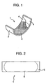
- the thus obtained plain bearing 1 is subjected to a finish machining to a final product as shown in Figs. 1 and 2.
- the plain bearing 1 produced by the above processes consists of the back metal 2; the bearing alloy layer 3 made of a copper alloy (see Fig. 3) being formed on the inner surface of the back metal 2; the intermediate layer 4 of Ni being formed on the inner surface of the bearing alloy layer 3 and having a thickness of 1.5 ⁇ m; and the overlay layer 5 of a Pb-Sn alloy being formed on the intermediate layer and having a thickness of 20 ⁇ m.
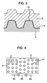
- the etched surface zone 6 of the bearing alloy layer 3 is of an uneven surface comprising a number of protrusions 10 which remain without etching.
- the protrusions 10 are arranged in accordance with two types of pattern (6a, 6b) as shown in an enlarged drawing of Fig. 4.
- the respective protrusions 10 have a square top shape of which side edges (each thereof has a length of 0.1 mm) are oblique by an angle of 45° to the circumferential side ends of the hemi-circular plain bearing.
- the two types of protrusion pattern (6a, 6b) which consist of a primary pattern 6a and a secondary pattern 6b, are arranged such that there exists a zone of pattern 6b, which consists of two rows of protrusions, between two zones of pattern 6a, each of which consists of three rows of protrusions.
- the protrusion lines in the pattern 6b differ from those in the pattern 6a in the axial direction such that the transverse protrusion lines of one of the patterns 6a and 6b correspond to the space areas between adjacent protrusion lines of the other of the patterns 6a and 6b. It is also noted that, at the both circumferential end zones other than the etched surface zone 6, the inner surface of the bearing alloy layer 3 remains smooth.
- the etched surface zone 6 includes a surface area rate of about 25% of the all protrusions 10.
- the embodiment plain bearing When the embodiment plain bearing is mounted in a housing (not shown in the drawings) and operatively used and the overlay layer wears with time progress to reach the wear level I as shown in Fig. 5, the intermediate layer 4 being formed on the protrusions 10 will be exposed.
- the surface area rate of the protrusions 10 in the etched surface zone 6 is only about 25%, while the mating shaft (not shown in the drawings) supported by the plain bearing is in sliding-contact with the intermediate layer 4 on the protrusions 10, it is also in contact with predominantly the soft overlay layer 5 which occupies the remaining surface area rate of about 75% in the etched surface zone 6 whereby the anti-seizure property can be held.
- the etching depth of the inner surface of the bearing alloy layer 3 is 20 ⁇ m
- the thickness of the intermediate layer 4 is 1.5 ⁇ m
- the thickness of the overlay layer 5 is 20 ⁇ m.
- the overlay layer 5, which is formed by plating has also a similar uneven inner surface having protrusions followed to that of the bearing alloy layer 3. This means that the mating shaft (not shown in the drawings) is supported primarily by protrusion parts of the overlay layer 5 at the initial operation stage while exhibiting excellent initial conformability and also excellent initial anti-seizure property because of flowing susceptibility of lubricant oil.
Landscapes
- Engineering & Computer Science (AREA)
- General Engineering & Computer Science (AREA)
- Mechanical Engineering (AREA)
- Sliding-Contact Bearings (AREA)
- ing And Chemical Polishing (AREA)
Abstract
Description
Claims (4)
- A plain bearing (1) comprising a back metal (2), a bearing alloy layer (3) provided on the inner surface of the back metal (2), an intermediate layer (4) provided on the bearing alloy layer (3) and an overlay layer (5) provided on the intermediate layer, wherein
the bearing alloy layer (3) has an inner surface being of a textured uneven surface, comprising a number of protrusions (10), which has been formed by etching of the inner surface provided with a mask; wherein
the intermediate layer (4) is formed on the uneven surface of the bearing alloy layer (3) so as to follow the textured uneven surface so that the intermediate layer (4) has also a textured uneven surface; characterized in that
the protrusions (10) are so arranged to form a patterned array of protrusion groups (6a, 6b) each of which comprise a plurality of protrusions (10) being aligned in both of the axial and circumferential directions of the plain bearing (1) such that the plurality of protrusions (10) form a plurality of axial rows and a plurality of circumferential lines. - A plain bearing according to claim 1, wherein the circumferential protrusion lines in one of the protrusion groups (6a) are not in alignment with the other circumferential protrusion lines in the other protrusion group (6b) adjacent to the former protrusion group.
- A plain bearing according to claim 1 or 2, wherein the protrusions (10) are independent from one another and have at least one cross-sectional form selected from the group consisting of a square, circle, a lozenge, and a ridge extending in an optional direction including the circumferential, perpendicular or oblique direction to the circumference.
- A method of producing a plain bearing (1) as defined in anyone of claims 1 to 3, the method comprising the steps of:coating the inner surface of the bearing alloy layer (3), which has been connected to the back metal (2), with a masking material defining a surface area part of the bearing alloy layer (3) to be etched;etching the coated inner surface of the bearing alloy layer (3) to form the textured uneven surface comprising the number of protrusions (10);removing the coated masking material from the inner surface of the bearing alloy layer (3);providing the intermediate layer (4) on the etched inner surface of the bearing alloy layer (3) so as to follow the textured uneven surface of the bearing alloy layer (3) so that the intermediate layer (4) has also the textured uneven surface; andcoating the surface of the intermediate layer (4) with the overlay layer (5).
Applications Claiming Priority (2)
| Application Number | Priority Date | Filing Date | Title |
|---|---|---|---|
| JP26100999 | 1999-09-14 | ||
| JP26100999A JP2001082481A (en) | 1999-09-14 | 1999-09-14 | Sliding bearing and its manufacture |
Publications (3)
| Publication Number | Publication Date |
|---|---|
| EP1085222A2 EP1085222A2 (en) | 2001-03-21 |
| EP1085222A3 EP1085222A3 (en) | 2002-09-25 |
| EP1085222B1 true EP1085222B1 (en) | 2005-11-16 |
Family
ID=17355799
Family Applications (1)
| Application Number | Title | Priority Date | Filing Date |
|---|---|---|---|
| EP00118279A Expired - Lifetime EP1085222B1 (en) | 1999-09-14 | 2000-09-05 | Plain bearing and producing method thereof |
Country Status (5)
| Country | Link |
|---|---|
| US (1) | US6491437B1 (en) |
| EP (1) | EP1085222B1 (en) |
| JP (1) | JP2001082481A (en) |
| AT (1) | ATE310178T1 (en) |
| DE (1) | DE60024021T2 (en) |
Families Citing this family (10)
| Publication number | Priority date | Publication date | Assignee | Title |
|---|---|---|---|---|
| DE50205771D1 (en) * | 2001-11-23 | 2006-04-13 | Univ Duisburg Essen | implant |
| JP2007239866A (en) * | 2006-03-08 | 2007-09-20 | Daido Metal Co Ltd | Sliding bearing |
| JP4994266B2 (en) * | 2008-02-27 | 2012-08-08 | 大同メタル工業株式会社 | Sliding member |
| JP5298838B2 (en) * | 2008-12-25 | 2013-09-25 | 大豊工業株式会社 | Swash plate and its manufacturing method |
| US8727622B2 (en) * | 2011-04-26 | 2014-05-20 | Senju Metal Industry Co., Ltd. | Sliding member |
| JP2014013036A (en) * | 2012-06-07 | 2014-01-23 | Ntn Corp | Swash plate for swash plate type compressor, method of manufacturing the same, and swash plate type compressor |
| DE102013109025A1 (en) * | 2013-08-21 | 2015-02-26 | Mag Ias Gmbh | sliding surface |
| US10737462B2 (en) * | 2016-08-24 | 2020-08-11 | Hyundai Motor Company | Method for coating surface of moving part of vehicle and moving part of vehicle manufactured by the same |
| CN108612759B (en) * | 2018-07-09 | 2020-06-23 | 武汉科技大学 | A tiltable thrust pad bearing with microtextured regions and slip surfaces |
| AT522612A1 (en) * | 2019-05-29 | 2020-12-15 | Miba Gleitlager Austria Gmbh | Method for manufacturing a multilayer plain bearing |
Citations (1)
| Publication number | Priority date | Publication date | Assignee | Title |
|---|---|---|---|---|
| DE1938010A1 (en) * | 1969-07-26 | 1971-02-18 | Glyco Metall Werke | Plain bearing with inhomogeneous running layer and process for its manufacture |
Family Cites Families (8)
| Publication number | Priority date | Publication date | Assignee | Title |
|---|---|---|---|---|
| AT385822B (en) | 1984-02-27 | 1988-05-25 | Miba Gleitlager Ag | COMPOSITE SLIDING BEARING |
| DE3415929A1 (en) | 1984-04-28 | 1985-10-31 | Glyco-Metall-Werke Daelen & Loos Gmbh, 6200 Wiesbaden | HIGH-DENSITY SLIDING BEARING WITH INHOMOGENIC SLIDING LAYER |
| GB8500282D0 (en) | 1985-01-05 | 1985-02-13 | Ae Plc | Bearings |
| DE3601319A1 (en) | 1985-01-18 | 1986-07-24 | Mazda Motor Corp., Hiroshima | METHOD FOR DESIGNING AN ABRASION-RESISTANT SLIDING SURFACE |
| JPS62283216A (en) | 1986-05-29 | 1987-12-09 | Taiho Kogyo Co Ltd | plain bearing |
| JP2852521B2 (en) * | 1988-11-21 | 1999-02-03 | 株式会社 小松製作所 | Plain bearings for internal combustion engines |
| JP2974044B2 (en) | 1994-03-18 | 1999-11-08 | 大豊工業株式会社 | Plain bearing |
| EP0758721B1 (en) | 1995-03-01 | 2000-08-30 | Taiho Kogyo Co., Ltd. | Slide bearing |
-
1999
- 1999-09-14 JP JP26100999A patent/JP2001082481A/en active Pending
-
2000
- 2000-08-23 US US09/644,303 patent/US6491437B1/en not_active Expired - Fee Related
- 2000-09-05 EP EP00118279A patent/EP1085222B1/en not_active Expired - Lifetime
- 2000-09-05 DE DE60024021T patent/DE60024021T2/en not_active Expired - Lifetime
- 2000-09-05 AT AT00118279T patent/ATE310178T1/en active
Patent Citations (1)
| Publication number | Priority date | Publication date | Assignee | Title |
|---|---|---|---|---|
| DE1938010A1 (en) * | 1969-07-26 | 1971-02-18 | Glyco Metall Werke | Plain bearing with inhomogeneous running layer and process for its manufacture |
Also Published As
| Publication number | Publication date |
|---|---|
| EP1085222A3 (en) | 2002-09-25 |
| EP1085222A2 (en) | 2001-03-21 |
| DE60024021D1 (en) | 2005-12-22 |
| US6491437B1 (en) | 2002-12-10 |
| ATE310178T1 (en) | 2005-12-15 |
| JP2001082481A (en) | 2001-03-27 |
| DE60024021T2 (en) | 2006-07-27 |
Similar Documents
| Publication | Publication Date | Title |
|---|---|---|
| US5295696A (en) | Combined oil ring | |
| US6491437B1 (en) | Plain bearing and producing method thereof | |
| EP1584828B1 (en) | Sliding bearing | |
| KR970009126B1 (en) | Sliding surface bearing for high loads | |
| CA1291631C (en) | Bearings | |
| US6062735A (en) | Corrosion resistant antifriction bearing and method for making same | |
| EP0422321B1 (en) | Plane bearing | |
| EP1092885B1 (en) | Plain bearing | |
| US6491436B1 (en) | Plain bearing | |
| US6497513B2 (en) | Plain bearing | |
| US8007178B2 (en) | Bearing materials and method for the production thereof | |
| KR100803881B1 (en) | Elastic Belt for Paper | |
| KR100839095B1 (en) | Sliding device | |
| EP1085223B1 (en) | Plain bearing | |
| JP2006329252A (en) | Rotating sliding structure between bearing and shaft and manufacturing method thereof | |
| US20040237307A1 (en) | Dynamic pressure bearing and method of manufacturing the same | |
| US6095013A (en) | Cam follower apparatus | |
| EP0434127B1 (en) | Bearings | |
| KR20230121369A (en) | Journal bearing and manufacturing method thereof | |
| KR20020013531A (en) | Sliding member | |
| RU2085327C1 (en) | Crystallizer for continuous steel slab casting machine | |
| US8317995B2 (en) | Electrode tool for electrochemical machining and method of manufacturing the same | |
| JP2005538322A (en) | Piston pin bushing | |
| JPH03255222A (en) | Eccentric bearing and manufacture thereof | |
| KR20240130238A (en) | Bearing for preventing electric corrosion and method thereof |
Legal Events
| Date | Code | Title | Description |
|---|---|---|---|
| PUAI | Public reference made under article 153(3) epc to a published international application that has entered the european phase |
Free format text: ORIGINAL CODE: 0009012 |
|
| 17P | Request for examination filed |
Effective date: 20000905 |
|
| AK | Designated contracting states |
Kind code of ref document: A2 Designated state(s): AT BE CH CY DE DK ES FI FR GB GR IE IT LI LU MC NL PT SE |
|
| AX | Request for extension of the european patent |
Free format text: AL;LT;LV;MK;RO;SI |
|
| PUAL | Search report despatched |
Free format text: ORIGINAL CODE: 0009013 |
|
| AK | Designated contracting states |
Kind code of ref document: A3 Designated state(s): AT BE CH CY DE DK ES FI FR GB GR IE IT LI LU MC NL PT SE |
|
| AX | Request for extension of the european patent |
Free format text: AL;LT;LV;MK;RO;SI |
|
| AKX | Designation fees paid |
Designated state(s): AT DE GB |
|
| 17Q | First examination report despatched |
Effective date: 20040901 |
|
| GRAP | Despatch of communication of intention to grant a patent |
Free format text: ORIGINAL CODE: EPIDOSNIGR1 |
|
| GRAS | Grant fee paid |
Free format text: ORIGINAL CODE: EPIDOSNIGR3 |
|
| GRAA | (expected) grant |
Free format text: ORIGINAL CODE: 0009210 |
|
| RIN1 | Information on inventor provided before grant (corrected) |
Inventor name: ISHIKAWA, HIDEOC/O DAIDO METAL COMPANY LTD. Inventor name: KAWACHI, TOSHIAKIC/O DAIDO METAL COMPANY LTD. Inventor name: SHIBAYAMA, TAKAYUKIC/O DAIDO METAL COMPANY LTD. Inventor name: YAMADA, TATSUOC/O DAIDO METAL COMPANY LTD. |
|
| AK | Designated contracting states |
Kind code of ref document: B1 Designated state(s): AT DE GB |
|
| REG | Reference to a national code |
Ref country code: GB Ref legal event code: FG4D |
|
| REF | Corresponds to: |
Ref document number: 60024021 Country of ref document: DE Date of ref document: 20051222 Kind code of ref document: P |
|
| PLBE | No opposition filed within time limit |
Free format text: ORIGINAL CODE: 0009261 |
|
| STAA | Information on the status of an ep patent application or granted ep patent |
Free format text: STATUS: NO OPPOSITION FILED WITHIN TIME LIMIT |
|
| 26N | No opposition filed |
Effective date: 20060817 |
|
| PGFP | Annual fee paid to national office [announced via postgrant information from national office to epo] |
Ref country code: AT Payment date: 20130829 Year of fee payment: 14 Ref country code: DE Payment date: 20130906 Year of fee payment: 14 |
|
| PGFP | Annual fee paid to national office [announced via postgrant information from national office to epo] |
Ref country code: GB Payment date: 20130927 Year of fee payment: 14 |
|
| REG | Reference to a national code |
Ref country code: DE Ref legal event code: R119 Ref document number: 60024021 Country of ref document: DE |
|
| REG | Reference to a national code |
Ref country code: AT Ref legal event code: MM01 Ref document number: 310178 Country of ref document: AT Kind code of ref document: T Effective date: 20140905 |
|
| GBPC | Gb: european patent ceased through non-payment of renewal fee |
Effective date: 20140905 |
|
| PG25 | Lapsed in a contracting state [announced via postgrant information from national office to epo] |
Ref country code: GB Free format text: LAPSE BECAUSE OF NON-PAYMENT OF DUE FEES Effective date: 20140905 Ref country code: DE Free format text: LAPSE BECAUSE OF NON-PAYMENT OF DUE FEES Effective date: 20150401 |
|
| PG25 | Lapsed in a contracting state [announced via postgrant information from national office to epo] |
Ref country code: AT Free format text: LAPSE BECAUSE OF NON-PAYMENT OF DUE FEES Effective date: 20140905 |