EP1084910A2 - Circuit and method for establishing two-way communication between the steering column and the steering wheel of a vehicle - Google Patents
Circuit and method for establishing two-way communication between the steering column and the steering wheel of a vehicle Download PDFInfo
- Publication number
- EP1084910A2 EP1084910A2 EP00120018A EP00120018A EP1084910A2 EP 1084910 A2 EP1084910 A2 EP 1084910A2 EP 00120018 A EP00120018 A EP 00120018A EP 00120018 A EP00120018 A EP 00120018A EP 1084910 A2 EP1084910 A2 EP 1084910A2
- Authority
- EP
- European Patent Office
- Prior art keywords
- circuit
- wheel
- column
- power
- data
- Prior art date
- Legal status (The legal status is an assumption and is not a legal conclusion. Google has not performed a legal analysis and makes no representation as to the accuracy of the status listed.)
- Withdrawn
Links
- 238000004891 communication Methods 0.000 title claims abstract description 13
- 238000000034 method Methods 0.000 title claims description 27
- 238000010304 firing Methods 0.000 claims abstract description 18
- 238000003860 storage Methods 0.000 claims abstract description 14
- 239000003990 capacitor Substances 0.000 claims description 50
- 238000012546 transfer Methods 0.000 claims description 30
- 238000004146 energy storage Methods 0.000 claims description 9
- 230000001105 regulatory effect Effects 0.000 claims description 3
- 230000003252 repetitive effect Effects 0.000 claims description 3
- 230000001276 controlling effect Effects 0.000 claims 2
- 230000008901 benefit Effects 0.000 description 3
- 230000008859 change Effects 0.000 description 3
- 230000004044 response Effects 0.000 description 3
- 230000004913 activation Effects 0.000 description 2
- 239000004020 conductor Substances 0.000 description 2
- 230000003247 decreasing effect Effects 0.000 description 2
- 238000001514 detection method Methods 0.000 description 2
- 230000000694 effects Effects 0.000 description 2
- 230000008569 process Effects 0.000 description 2
- 238000004804 winding Methods 0.000 description 2
- 230000006978 adaptation Effects 0.000 description 1
- 238000013459 approach Methods 0.000 description 1
- 230000005540 biological transmission Effects 0.000 description 1
- 238000010276 construction Methods 0.000 description 1
- 230000009849 deactivation Effects 0.000 description 1
- 230000001934 delay Effects 0.000 description 1
- 238000013461 design Methods 0.000 description 1
- 238000004519 manufacturing process Methods 0.000 description 1
- 239000000203 mixture Substances 0.000 description 1
- 239000002991 molded plastic Substances 0.000 description 1
- 238000003825 pressing Methods 0.000 description 1
- 238000004513 sizing Methods 0.000 description 1
- 230000001960 triggered effect Effects 0.000 description 1
Images

Classifications
-
- B—PERFORMING OPERATIONS; TRANSPORTING
- B62—LAND VEHICLES FOR TRAVELLING OTHERWISE THAN ON RAILS
- B62D—MOTOR VEHICLES; TRAILERS
- B62D6/00—Arrangements for automatically controlling steering depending on driving conditions sensed and responded to, e.g. control circuits
-
- B—PERFORMING OPERATIONS; TRANSPORTING
- B60—VEHICLES IN GENERAL
- B60R—VEHICLES, VEHICLE FITTINGS, OR VEHICLE PARTS, NOT OTHERWISE PROVIDED FOR
- B60R16/00—Electric or fluid circuits specially adapted for vehicles and not otherwise provided for; Arrangement of elements of electric or fluid circuits specially adapted for vehicles and not otherwise provided for
- B60R16/02—Electric or fluid circuits specially adapted for vehicles and not otherwise provided for; Arrangement of elements of electric or fluid circuits specially adapted for vehicles and not otherwise provided for electric constitutive elements
- B60R16/023—Electric or fluid circuits specially adapted for vehicles and not otherwise provided for; Arrangement of elements of electric or fluid circuits specially adapted for vehicles and not otherwise provided for electric constitutive elements for transmission of signals between vehicle parts or subsystems
- B60R16/027—Electric or fluid circuits specially adapted for vehicles and not otherwise provided for; Arrangement of elements of electric or fluid circuits specially adapted for vehicles and not otherwise provided for electric constitutive elements for transmission of signals between vehicle parts or subsystems between relatively movable parts of the vehicle, e.g. between steering wheel and column
Definitions
- the disclosed invention relates to vehicle control systems. More particularly, the disclosed invention pertains to a control system capable of generating an air bag deployment signal upon a vehicle collision for an air bag stored in a steering wheel/column while also transferring a biasing power signal to control circuitry in the steering wheel and communicating selected driver control signals between the wheel and the column.
- the slip rings consisted of a ball contact located on the steering wheel and a circular conductor which was part of a "clock spring".
- the clock spring was a molded plastic part which housed a two conductor ribbon cable that connected the air bag to its control module. Such a clock spring is capable of maintaining electrical connections during rotation of the wheel.
- slip ring arrangements have always suffered from reliability and performance problems due to the inherent nature of the slip ring structure itself.
- the electrical integrity of the contacting methods necessarily depreciate over time and from dirt and/or wear and varying ambient conditions.
- the complexity and cost to manufacture clock springs have increased, and their reliability have decreased. Attempting to compensate for the increased cost and decreased reliability of clock springs, some applications have included the use of a rotary transformer between the steering wheel and the steering column to generate a "contactless" system.
- This invention comprises an electronic control circuit and method using a rotary transformer to facilitate the transfer of power and two-way communications between the column and steering wheel of a vehicle.
- the invented apparatus and method also provide for the efficient firing of air bag squibs.
- the invented circuit and method consist of a steering column circuit and a steering wheel circuit coupled together by a rotary transformer through which the column circuit provides power to the wheel circuit, and through which both circuits transfer data to the other.
- the primary magnetic coil of the rotary transformer is associated with the column circuit, and the secondary magnetic coil of the transformer is associated with the wheel circuit.
- the column circuit is powered by the vehicle's battery.
- a surge protection circuit is disposed between the vehicle battery and the rest of the column circuit to protect the system against transients on the battery.
- the vehicle battery provides power to a column circuit microprocessor.
- the column circuit microprocessor receives various data input signals, including an input signal relating to when the vehicle air bags are to be deployed.
- Outputs from the column microprocessor include a signal to a coil driver circuit and a signal to a capacitor connect circuit.
- the capacitor connect circuit is connected to a tuning capacitor which is connected to the rotary transformer.
- the wheel circuit includes two storage capacitors that store power transferred from the column circuit to the wheel circuit and which act as the power source for the wheel circuit.
- the wheel circuit also includes a wheel circuit microprocessor that receives and transmits various inputs and outputs relating to the control of functions on the vehicle steering wheel.
- the wheel circuit also includes a squib driver circuit which controls the firing of air bag squibs in response to a "fire squib" control signal received from the column circuit.
- the disclosed circuit repetitively alternates between a power transfer mode and a data transfer mode by multiplexing time across the rotary transformer.
- the column microprocessor supplies a pulse train to the coil driver circuit, which in turn periodically applies full power from the vehicle battery to the transformer's primary coil, or "column coil”.
- the column microprocessor and the capacitor connect circuit 36 disconnect the tuning capacitor CR from the column coil.
- the tuning capacitor is reconnected, at which time energy stored in the tuning capacitor is supplied across the rotary transformer.
- a voltage-level feedback switch from the wheel circuit to the column circuit allows the column microprocessor to adjust the width of the pulses supplied to the column coil to maintain a constant power level at the wheel circuit.
- the power supplied by the column circuit to the wheel circuit is stored in the storage capacitors. The energy in the storage capacitors is used to power the components of the wheel circuit, including the squib driver circuit.
- the column microprocessor After a preset length of time allotted for the power transfer mode, the column microprocessor causes the control circuit to change to the data transfer mode. During this mode, the column circuit transmits a preset number of data bits to the wheel circuit across the rotary transformer, and then the wheel circuit transmits a preset number of bits to the column circuit across the rotary transformer. Then, the circuit returns to the power transfer mode and repeats the sequence.
- the column microprocessor If at any time the column microprocessor receives a signal to activate the vehicle air bags, the column microprocessor immediately changes the mode of the control circuit to "fire squib" mode.
- the column microprocessor transmits a "fire squib” control signal across the rotary transformer to the wheel microprocessor which then sends a signal to the squib driver circuit to fire the air bag squibs.
- the disclosed electronic control system 20 comprises a steering column circuit 22 and steering wheel circuit 24. Both circuits are preferably fabricated on circular printed circuit boards.
- wheel circuit 24 is mounted to the steering wheel of the vehicle (not shown)
- column circuit 22 is mounted to the steering column of the vehicle (not shown).
- Column circuit 22 receives power from a power supply 26, preferably the vehicle's 12-volt battery, which is passed through a surge protection circuit 28 to protect the circuitry of the control circuit 20 from various transients that can appear on the power source 26.
- Power supply 26 provides power to a voltage regulator 30, which provides regulated power to a column circuit microprocessor 32.
- the voltage regulator 30 is preferably a 5-volt regulator.
- Power source 26 also provides power to a column coil 40 which serves as the primary winding of rotary transformer X1.
- the voltage across the column coil 40 is referred to as V p , and the current passing through the column coil is referred to as I p .
- the column coil 40 is preferably assembled to the bottom side of the column circuit board (not shown).
- Transformer X1 is preferably an air core transformer.
- a coil driver circuit 34 receives signals from the column microprocessor 32 and, in response thereto, regulates the power provided by the power supply 26 to the column coil 40.
- Column coil 40 communicates with a column data receiver circuit 38, which provides input to the column microprocessor 32.
- Resistor R1 is connected in parallel across column coil 40 and between surge protection circuit 28 and coil driver circuit 34.
- a tuning capacitor CR is connected between resistor R1 and a capacitor connect circuit 36.
- Capacitor connect circuit 36 receives input signals from column microprocessor 32, and, based thereon, connects and disconnects tuning capacitor CR to/from column coil 40.
- additional input signals to the column microprocessor 32 include a squib 100% signal 46, a squib 70% signal 48, an ignition signal 50, and a data in signal 52.
- Additional output signals from the column microprocessor 32 include a data out signal 54 and a horn signal 56. The purposes of functions of these additional input and output signals to the column microprocessor 32 are well-known to one of ordinary skill in the art.
- the wheel circuit 24 includes a wheel circuit coil 60 which constitutes the secondary winding of the transformer X1.
- the voltage potential across wheel coil 60 is referred to as V s .
- Wheel coil 60 is preferably assembled to the bottom side of the wheel circuit board containing wheel circuit 22.
- Wheel coil 60 is connected to a full wave rectifier 62, and energy supplied to wheel coil 60 charges energy storage capacitors C1 and C2 through full wave rectifier 62.
- the energy stored in capacitors C1 and C2 constitute the power source for wheel circuit 22.
- the voltage signal from the full wave rectifier 62 that biases capacitors C1 and C2 is referred to as V18 and the voltage level across C2 alone is referred to as V9.
- Wheel coil 60 is connected to a power detector circuit 64 which is connected to a power enable circuit 66.
- Power detector circuit 64 receives signals from column circuit 22 through rotary transformer X1 and, based upon those signals, determines if the vehicle's ignition is on, and thus whether power is being supplied from the power supply 26 to the control circuit 20.
- Power detector circuit 64 provides a signal to a power enable circuit 66 that shuts down the wheel circuit 24 if the power detector circuit 64 determines that the column circuit 22 is not supplying power to the wheel circuit 24.
- the voltage regulator 70 is preferably a 5-volt regulator.
- wheel microprocessor 72 receives input signals from a diagnostics signal 74, a wheel switch signal 76, a horn signal 78, and a bias voltage V18.
- the wheel microprocessor 72 provides output signals to a background dimmer circuit 80, an annunciator dimmer circuit 82, and a wheel data driver circuit 84.
- the purposes and functions of these various input signals and output signals to wheel microprocessor 72 are well-known by one of ordinary skill in the art.
- a wheel data driver circuit 84 receives output signals from wheel microprocessor 72 and provides these output signals to wheel coil 60 for transfer to the column circuit 22.
- the wheel microprocessor 72 also receives input from the wheel data receiver circuit 86 which itself receives input from the wheel coil 60.
- a horn data driver 88 receives input from a horn signal 78 and provides output to the wheel coil 60.
- the horn data driver 88 is powered by voltage V9.
- Resistor R2 is connected in parallel across the terminals of wheel coil 60.
- the main source of power for the entire system 20 originates from the power supply 26 in the column circuit 22. Power from the power supply 26 must be provided from the column circuit 22 to the wheel circuit 24. Moreover, various commands and other data originate in both the column circuit 22 and the wheel circuit 24 and must be communicated between the two circuits. For example, commands originating in the vehicle system with the steering wheel as an activity vector, such as "fire the 70% squib”, “illuminate the cruise control annunciator", or "change the steering wheel's background dimming level to 32%", must be passed to the wheel microprocessor 72.
- the rotary transformer X1 provides the communication link between the steering wheel circuit 22 and the steering wheel circuit 24 for both power supply purposes and two-way data transfer. Unlike the known slip ring or clock spring based systems, the disclosed invention does not have any wires connecting the vehicle steering wheel circuits and the column circuits.
- a "normal mode" of operation of the control circuit 20 the efficient transfer of power and the two-way flow of data across the rotary transformer X1 are implemented by establishing two operational modes - a power transfer mode and a data transfer mode - and multiplexing the power transfer mode and the data transfer modes.
- a "fire squib” mode is also employed, which, when triggered, immediately overrides both the power transfer mode and the data transfer mode to enable the system to fire the air bag squibs.
- the normal mode of the control circuit 20 is characterized by repetitively alternating between the power transfer mode and the data transfer mode.
- the column circuit 22 provides power to the wheel circuit 24.
- Column microprocessor 32 supplies a pulse train to coil driver circuit 34, which in turn periodically applies full power from the power source 26 to the column coil 40.
- the pulse train is supplied at a frequency of approximately 25kHz.
- the total amount of power transferred from the column circuit 22 to the wheel circuit 24 is determined by the duration or length of the voltage pulses provided by the power supply 26.
- the width of each pulse of power is controlled and calculated to deliver just enough power from power supply 26 during each driving pulse to produce a fixed voltage on storage capacitors C1 and C2. In a preferred embodiment, the width of each power pulse is set to deliver nominal voltage levels on storage capacitors C1 and C2 of 18 volts and 9 volts, respectively.
- a preferred set of waveforms for the power mode operation are shown in Figure 2.
- the column microprocessor 32 and the capacitor connect circuit 36 disconnect the tuning capacitor CR.
- the column coil voltage V p is very close to ground reference at this time, and the current through column coil 40, I p , ramps up linearly.
- the column microprocessor 32 and the capacitor connect circuit 36 reconnect the tuning capacitor CR, and, as a result, the column coil voltage V p rings sinusoidally.
- the pulse supplied to the column coil 40 is "off"
- the energy stored in column coil 40 is coupled to both the tuning capacitor CR and to the wheel coil 60.
- the tuning capacitor CR By connecting the tuning capacitor CR to the column coil 40 only during the time that the coil driver circuit 34 is turned “off", the power required to drive the control circuit 20 is minimized and the energy recovered from column coil 40 is maximized.
- the use of the tuning capacitor CR facilitates a continuous supply of power from the column circuit to the wheel circuit and facilitates the use of energy stored in the leakage inductance of the column coil.
- the disclosed system and method is in contrast to the known method of transferring the stored energy to a Zener diode "protection device", where the energy stored in the leakage inductance of the column coil is dissipated as heat.
- the wheel power load can be highly variable as a result of the selective activation and deactivation of various options, such as background lights and annunciators on the steering wheel.
- the voltage bias V18 is affected by factors such as the width of the gap between column coil 40 and wheel coil 60, as well as the voltage level of the power source 26. Together, these parameter variations can cause squib firing voltage V18 to vary significantly. This is not a desirable condition. To compensate for this potential variation, squib firing voltage V18 is monitored by wheel microprocessor 72, which receives squib firing voltage V18 as an input directly from the full wave rectifier 62.
- a digitally-encoded copy of the squib firing voltage V18 is coupled back to the column microprocessor 32 through the wheel data driver circuit 84 and rotary transformer X1.
- the column microprocessor 32 uses the digitally-encoded squib firing voltage V18 as a feedback input signal to calculate a compensating pulse width. Accordingly, the column microprocessor 32 adjusts the driving pulse width to either raise or lower the energy supplied across rotary transformer X1, depending upon whether the squib firing voltage V18 is too high or too low. This methodology maintains the squib firing voltage V18 approximately constant.
- column microprocessor 32 After the control circuit 20 has operated in the power transfer mode for its preset period of time, column microprocessor 32 causes the circuit 20 to change to its data transfer mode. In this mode, data is transferred across the rotary transformer X1, first from the column to the wheel, and second from the wheel to the column. The control circuit 20 is converted to the data transfer mode of operation by disconnecting tuning capacitor CR from the rotary transformer X1. To accomplish this, column microprocessor 32 supplies a low level signal to the capacitor connect circuit 36 which cuts off the tuning capacitor CR. With tuning capacitor CR disconnected, transformer X1 is inherently a wide bandwidth device that can transfer bi-directional data between its coils 40 and 60 efficiently and at high speed.
- the column microprocessor 32 After disconnecting tuning capacitor CR, the column microprocessor 32 effects a delay sufficient to allow the existing energy in the rotary transformer X1 to dissipate. In a preferred embodiment, that time is approximately 80 microseconds. Thereafter, the column circuit 22 begins to transfer a preset number of data bits across the rotary transformer X1 to the wheel circuit 24 at a preset transmission rate, preferably 16 bits transferred at 25 kHz. In a preferred embodiment of the invention, the logical "0" and logical "1" data bits transferred between the column circuit 22 and the wheel circuit 24 are signified by voltage pulses of different lengths. For example, a voltage pulse of a relatively short duration is considered a logical "0", and a voltage pulse of a relatively long duration is considered a logical "1".
- the wheel microprocessor 72 receives the sent data bits and acts upon them accordingly. After the preset number of data bits have been sent from the column circuit 22 to the wheel circuit 24, a nominal delay time is employed to dissipate any remaining voltage in the rotary transformer X1. Then, the wheel circuit 24 sends a preset number of data bits across transformer X1 to column circuit 32, after which the control circuit 20 is switched back into its power transfer mode. The above-described methodology then repeats itself. With respect to the data bits that are transferred back and forth between the column circuit and the wheel circuit, the number of bits may be varied depending upon the number of possible control signals that each circuit needs to convey to the other.
- the first two bits of each data transfer consist of voltage pulse durations corresponding to a logical "0" and a logical "1" that are used for calibration purposes.
- the column microprocessor 32 or the wheel microprocessor 72 depending upon which circuit is receiving data, averages the voltage levels of the first two bits received (the "calibration" bits) and then considers voltage levels below the calculated average to be logic value "0" and voltage levels above the calculated average to be logic value "1".
- the vehicle's crash accelerator system (not shown) provides a "fire squib" command to the column microprocessor 32.
- the column microprocessor 32 Upon receipt of the "fire squib" command, the column microprocessor 32 immediately terminates the current operating mode (either power transfer mode or data transfer mode). The column microprocessor 32 then delays a preset length of time, preferably about 80 microseconds, to permit all of the stored energy in the rotary transformer X1 to dissipate.
- the column microprocessor 32 transmits a "fire squib” command through the coil driver circuit 34 and rotary transformer X1 to the wheel data receiver circuit 86 and ultimately the wheel microprocessor 72.
- the "fire squib" command comprises three pulses delivered at 40 microsecond intervals.
- the first pulse is ten microseconds wide, which differentiates the "fire squib” command from all other commands.
- the second pulse is either three microseconds or one microseconds wide, which is interpreted by the wheel microprocessor as an indication to either fire or not fire the 30% squib, respectively. If the second pulse is three microseconds wide, the command is interpreted to fire the 30% squib.
- the third pulse is either three microseconds or one microsecond wide, and it is interpreted as a command to either fire or not fire the 70% squib, respectively. If the third pulse is three microseconds wide, the command is interpreted to fire the 70% squib.
- the wheel microprocessor 72 Based upon the "fire squib" command received from the column microprocessor 32, the wheel microprocessor 72 formats a control signal defining the squib fire pulse duration and whether the 30% squib, the 70% squib, or both are to be fired. The wheel microprocessor 72 sends this formatted control signal to the squib driver circuit 68.
- the squib driver control circuit 68 controls the firing current to the appropriate squibs, as is well-known in the art.
- the column microprocessor 32 When the vehicle's ignition is turned off, the column microprocessor 32 turns off coil driver circuit 34, capacitor connect circuit 36 and column data receiver circuit 38, and column microprocessor 32 enters a sleep mode that consumes very little power from the vehicle's power supply 26 (battery).
- the power detection circuit 64 When column microprocessor 32 does not present power pulses to the power detection circuit 64 for more than a preset period of time, the power detection circuit 64 turns off the power enable circuit 66, which puts the entire wheel circuit 24, except for the horn data driver 28 (for reasons explained hereinafter), in shutdown mode.
- that preset period is approximately 500 milliseconds.
- the disclosed invention has several advantages over known system having direct connections between the column circuits and the wheel circuits.
- the disclosed invention is a much more efficient circuit and method for providing power and two-way communications across a rotary transformer.
- the disclosed invention provides an improved circuit and method for firing air bag squibs without direct wiring between a vehicle's steering column and steering wheel.
- Another advantage of the disclosed invention is its ability to permit the vehicle's horn to be activated with the vehicle's ignition turned off.
- Known systems having direct connections between the column circuits and the wheel circuits must rely on low power polling methods operating through the rotary transformer to identify horn switch closure by a user.
- the disclosed invention permits the vehicle's horn to be used when the ignition is off by drawing on the power stored in storage capacitor C2.
- Horn firing voltage V9 is connected to horn data driver 78.
- the horn data driver 78 is in standby mode until a "fire horn" signal 78 resulting from the user pressing the horn button on the steering wheel is presented to the horn data driver 88.
- the horn data driver 88 Upon receiving a "fire horn" signal 78, the horn data driver 88 generates a pulse that is coupled back through the rotary transformer X1 where it wakes up the column microprocessor 32 from its low current drain sleep mode. In response, column microprocessor 32 generates a "horn activate” signal. If the system is designed to permit activation of the horn while the vehicle's ignition is off, then the column microprocessor 32 will be required to be awakened for a few milliseconds at about one minute intervals to replace the energy lost from the storage capacitors C1 and C2 through normal circuit leakage.
- Another advantage of the disclosed invention is its ability to successively fire the air bag squibs for at least 350 milliseconds after the vehicle's battery is disconnected. This feature is important because a front end collision could sever the vehicle's battery connection before the vehicle's accelerator system provides a "fire squib" signal.
- the disclosed invention permits the squib driver circuit 68 to continue to receive power and thus fire the air bag squibs after the vehicle's battery is disconnected because the power supply to the squib driver circuit 68 is maintained in the storage capacitors C1, C2. By properly sizing storage capacitors C1 and C2, they can store sufficient energy to permit the squib driver circuit 68 to fire the squibs with the maximum possible load for a time period greater than 350 milliseconds.
Landscapes
- Engineering & Computer Science (AREA)
- Mechanical Engineering (AREA)
- Chemical & Material Sciences (AREA)
- Combustion & Propulsion (AREA)
- Transportation (AREA)
- Air Bags (AREA)
- Steering Controls (AREA)
- Near-Field Transmission Systems (AREA)
Abstract
Description
- The disclosed invention relates to vehicle control systems. More particularly, the disclosed invention pertains to a control system capable of generating an air bag deployment signal upon a vehicle collision for an air bag stored in a steering wheel/column while also transferring a biasing power signal to control circuitry in the steering wheel and communicating selected driver control signals between the wheel and the column.
- When vehicle air bags were initially introduced on the market, it was necessary to remove driver control functions from the steering wheel and install them on stalks that emanated from the steering column. Typically, the only two items which remained wheel-mounted were the air bags and the horn. The signal for the horn was transferred from the wheel to the column through slip rings. The slip rings consisted of a ball contact located on the steering wheel and a circular conductor which was part of a "clock spring". The clock spring was a molded plastic part which housed a two conductor ribbon cable that connected the air bag to its control module. Such a clock spring is capable of maintaining electrical connections during rotation of the wheel.
- The numerous design concepts comprising adaptations of slip rings and clock rings have been fraught with problems and are of limited economic and practical value. Slip ring arrangements have always suffered from reliability and performance problems due to the inherent nature of the slip ring structure itself. The electrical integrity of the contacting methods necessarily depreciate over time and from dirt and/or wear and varying ambient conditions. In addition, as the demand for the placement of driver controls back onto the steering wheel has become greater, the complexity and cost to manufacture clock springs have increased, and their reliability have decreased. Attempting to compensate for the increased cost and decreased reliability of clock springs, some applications have included the use of a rotary transformer between the steering wheel and the steering column to generate a "contactless" system. But the known approaches for firing the gas generators (squibs) that deploy the air bags all use a direct firing method which necessitates a complex and expensive rotary transformer. Moreover, the known methods for transferring data between steering wheel and the column require a transformer with very limited in-line and runout assembly tolerances.
- Accordingly, it is desirable to have an improved apparatus and method for firing air bag squibs and for transferring power and data between the vehicle steering wheel and the steering column.
- This invention comprises an electronic control circuit and method using a rotary transformer to facilitate the transfer of power and two-way communications between the column and steering wheel of a vehicle. The invented apparatus and method also provide for the efficient firing of air bag squibs. The invented circuit and method consist of a steering column circuit and a steering wheel circuit coupled together by a rotary transformer through which the column circuit provides power to the wheel circuit, and through which both circuits transfer data to the other. The primary magnetic coil of the rotary transformer is associated with the column circuit, and the secondary magnetic coil of the transformer is associated with the wheel circuit.
- The column circuit is powered by the vehicle's battery. A surge protection circuit is disposed between the vehicle battery and the rest of the column circuit to protect the system against transients on the battery. The vehicle battery provides power to a column circuit microprocessor. The column circuit microprocessor receives various data input signals, including an input signal relating to when the vehicle air bags are to be deployed. Outputs from the column microprocessor include a signal to a coil driver circuit and a signal to a capacitor connect circuit. The capacitor connect circuit is connected to a tuning capacitor which is connected to the rotary transformer.
- The wheel circuit includes two storage capacitors that store power transferred from the column circuit to the wheel circuit and which act as the power source for the wheel circuit. The wheel circuit also includes a wheel circuit microprocessor that receives and transmits various inputs and outputs relating to the control of functions on the vehicle steering wheel. The wheel circuit also includes a squib driver circuit which controls the firing of air bag squibs in response to a "fire squib" control signal received from the column circuit.
- During normal operation, the disclosed circuit repetitively alternates between a power transfer mode and a data transfer mode by multiplexing time across the rotary transformer. The column microprocessor supplies a pulse train to the coil driver circuit, which in turn periodically applies full power from the vehicle battery to the transformer's primary coil, or "column coil". When the pulses supplied to the column coil by the coil driver are "on", the column microprocessor and the capacitor connect
circuit 36 disconnect the tuning capacitor CR from the column coil. When the pulses are "off", the tuning capacitor is reconnected, at which time energy stored in the tuning capacitor is supplied across the rotary transformer. By connecting the tuning capacitor CR to the column coil only during the time that the coil driver circuit is turned "off", the power required to drive the control circuit is minimized and the energy recovered from the column coil is maximized. A voltage-level feedback switch from the wheel circuit to the column circuit allows the column microprocessor to adjust the width of the pulses supplied to the column coil to maintain a constant power level at the wheel circuit. The power supplied by the column circuit to the wheel circuit is stored in the storage capacitors. The energy in the storage capacitors is used to power the components of the wheel circuit, including the squib driver circuit. - After a preset length of time allotted for the power transfer mode, the column microprocessor causes the control circuit to change to the data transfer mode. During this mode, the column circuit transmits a preset number of data bits to the wheel circuit across the rotary transformer, and then the wheel circuit transmits a preset number of bits to the column circuit across the rotary transformer. Then, the circuit returns to the power transfer mode and repeats the sequence.
- If at any time the column microprocessor receives a signal to activate the vehicle air bags, the column microprocessor immediately changes the mode of the control circuit to "fire squib" mode. The column microprocessor transmits a "fire squib" control signal across the rotary transformer to the wheel microprocessor which then sends a signal to the squib driver circuit to fire the air bag squibs.
-
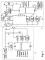
- Figure 1 shows a detailed illustration of the disclosed control circuit according to a preferred embodiment of the invention.
- Figure 2 shows timing wave forms relating to the operation of the disclosed control circuit in the power mode according to a preferred embodiment of the invention.
-
- Referring to Figure 1, the disclosed electronic control system 20 comprises a
steering column circuit 22 andsteering wheel circuit 24. Both circuits are preferably fabricated on circular printed circuit boards. In a preferred embodiment,wheel circuit 24 is mounted to the steering wheel of the vehicle (not shown), andcolumn circuit 22 is mounted to the steering column of the vehicle (not shown). -
Column circuit 22 receives power from apower supply 26, preferably the vehicle's 12-volt battery, which is passed through asurge protection circuit 28 to protect the circuitry of the control circuit 20 from various transients that can appear on thepower source 26. Various surge protection circuits are well-known to one of ordinary skill in the art.Power supply 26 provides power to avoltage regulator 30, which provides regulated power to acolumn circuit microprocessor 32. Thevoltage regulator 30 is preferably a 5-volt regulator.Power source 26 also provides power to a column coil 40 which serves as the primary winding of rotary transformer X1. The voltage across the column coil 40 is referred to as Vp, and the current passing through the column coil is referred to as Ip. The column coil 40 is preferably assembled to the bottom side of the column circuit board (not shown). Transformer X1 is preferably an air core transformer. - A
coil driver circuit 34 receives signals from thecolumn microprocessor 32 and, in response thereto, regulates the power provided by thepower supply 26 to the column coil 40. Column coil 40 communicates with a columndata receiver circuit 38, which provides input to thecolumn microprocessor 32. - Resistor R1 is connected in parallel across column coil 40 and between
surge protection circuit 28 andcoil driver circuit 34. A tuning capacitor CR is connected between resistor R1 and a capacitor connectcircuit 36. Capacitor connectcircuit 36 receives input signals fromcolumn microprocessor 32, and, based thereon, connects and disconnects tuning capacitor CR to/from column coil 40. In a preferred embodiment, additional input signals to thecolumn microprocessor 32 include asquib 100% signal 46, asquib 70% signal 48, anignition signal 50, and a data insignal 52. Additional output signals from thecolumn microprocessor 32 include a data outsignal 54 and ahorn signal 56. The purposes of functions of these additional input and output signals to thecolumn microprocessor 32 are well-known to one of ordinary skill in the art. - The
wheel circuit 24 includes a wheel circuit coil 60 which constitutes the secondary winding of the transformer X1. The voltage potential across wheel coil 60 is referred to as Vs. Wheel coil 60 is preferably assembled to the bottom side of the wheel circuit board containingwheel circuit 22. Wheel coil 60 is connected to afull wave rectifier 62, and energy supplied to wheel coil 60 charges energy storage capacitors C1 and C2 throughfull wave rectifier 62. The energy stored in capacitors C1 and C2 constitute the power source forwheel circuit 22. The voltage signal from thefull wave rectifier 62 that biases capacitors C1 and C2 is referred to as V18 and the voltage level across C2 alone is referred to as V9. - Wheel coil 60 is connected to a
power detector circuit 64 which is connected to a power enablecircuit 66.Power detector circuit 64 receives signals fromcolumn circuit 22 through rotary transformer X1 and, based upon those signals, determines if the vehicle's ignition is on, and thus whether power is being supplied from thepower supply 26 to the control circuit 20.Power detector circuit 64 provides a signal to a power enablecircuit 66 that shuts down thewheel circuit 24 if thepower detector circuit 64 determines that thecolumn circuit 22 is not supplying power to thewheel circuit 24. Thevoltage regulator 70 is preferably a 5-volt regulator. - In a preferred embodiment, wheel microprocessor 72 receives input signals from a
diagnostics signal 74, a wheel switch signal 76, ahorn signal 78, and a bias voltage V18. The wheel microprocessor 72 provides output signals to a backgrounddimmer circuit 80, an annunciator dimmer circuit 82, and a wheeldata driver circuit 84. The purposes and functions of these various input signals and output signals to wheel microprocessor 72 are well-known by one of ordinary skill in the art. - A wheel
data driver circuit 84 receives output signals from wheel microprocessor 72 and provides these output signals to wheel coil 60 for transfer to thecolumn circuit 22. The wheel microprocessor 72 also receives input from the wheeldata receiver circuit 86 which itself receives input from the wheel coil 60. Ahorn data driver 88 receives input from ahorn signal 78 and provides output to the wheel coil 60. Thehorn data driver 88 is powered by voltage V9. Resistor R2 is connected in parallel across the terminals of wheel coil 60. - In operation, the main source of power for the entire system 20 originates from the
power supply 26 in thecolumn circuit 22. Power from thepower supply 26 must be provided from thecolumn circuit 22 to thewheel circuit 24. Moreover, various commands and other data originate in both thecolumn circuit 22 and thewheel circuit 24 and must be communicated between the two circuits. For example, commands originating in the vehicle system with the steering wheel as an activity vector, such as "fire the 70% squib", "illuminate the cruise control annunciator", or "change the steering wheel's background dimming level to 32%", must be passed to the wheel microprocessor 72. Similarly, data and commands originating at the steering wheel, such as "blow the horn", "increase the radio sound level", or "the squib supply voltage is 15.5 volts", must be passed to thecolumn microprocessor 32. In the disclosed invention, the rotary transformer X1 provides the communication link between thesteering wheel circuit 22 and thesteering wheel circuit 24 for both power supply purposes and two-way data transfer. Unlike the known slip ring or clock spring based systems, the disclosed invention does not have any wires connecting the vehicle steering wheel circuits and the column circuits. - In a "normal mode" of operation of the control circuit 20, the efficient transfer of power and the two-way flow of data across the rotary transformer X1 are implemented by establishing two operational modes - a power transfer mode and a data transfer mode - and multiplexing the power transfer mode and the data transfer modes. A "fire squib" mode is also employed, which, when triggered, immediately overrides both the power transfer mode and the data transfer mode to enable the system to fire the air bag squibs.
- In a preferred embodiment of the invention, the normal mode of the control circuit 20 is characterized by repetitively alternating between the power transfer mode and the data transfer mode. First, operating in the power transfer mode, the
column circuit 22 provides power to thewheel circuit 24.Column microprocessor 32 supplies a pulse train tocoil driver circuit 34, which in turn periodically applies full power from thepower source 26 to the column coil 40. In a preferred embodiment, the pulse train is supplied at a frequency of approximately 25kHz. The total amount of power transferred from thecolumn circuit 22 to thewheel circuit 24 is determined by the duration or length of the voltage pulses provided by thepower supply 26. The width of each pulse of power is controlled and calculated to deliver just enough power frompower supply 26 during each driving pulse to produce a fixed voltage on storage capacitors C1 and C2. In a preferred embodiment, the width of each power pulse is set to deliver nominal voltage levels on storage capacitors C1 and C2 of 18 volts and 9 volts, respectively. - A preferred set of waveforms for the power mode operation are shown in Figure 2. When the pulses supplied to the column coil 40 by the
coil driver circuit 34 are "on", as shown in Figure 2, thecolumn microprocessor 32 and thecapacitor connect circuit 36 disconnect the tuning capacitor CR. The column coil voltage Vp is very close to ground reference at this time, and the current through column coil 40, Ip, ramps up linearly. At the end of each "on" pulse, thecolumn microprocessor 32 and thecapacitor connect circuit 36 reconnect the tuning capacitor CR, and, as a result, the column coil voltage Vp rings sinusoidally. During this phase, when the pulse supplied to the column coil 40 is "off", the energy stored in column coil 40 is coupled to both the tuning capacitor CR and to the wheel coil 60. The energy coupled from the column coil 40 to the wheel coil 60 charges the storage capacitors C1 and C2, one when the coil driver circuit is "on" (the "driven" phase) and the other when the coil driver circuit is "off" (the "ringing" phase). Figure 2 illustrate the resulting voltage potential, Vs, across the wheel coil 60 compared to the pulse train supplied by thecoil driver circuit 34. This repetitive process is maintained for a preset period of time while the circuit is in the power transfer mode. - By connecting the tuning capacitor CR to the column coil 40 only during the time that the
coil driver circuit 34 is turned "off", the power required to drive the control circuit 20 is minimized and the energy recovered from column coil 40 is maximized. The use of the tuning capacitor CR facilitates a continuous supply of power from the column circuit to the wheel circuit and facilitates the use of energy stored in the leakage inductance of the column coil. The disclosed system and method is in contrast to the known method of transferring the stored energy to a Zener diode "protection device", where the energy stored in the leakage inductance of the column coil is dissipated as heat. - It should be appreciated that the wheel power load can be highly variable as a result of the selective activation and deactivation of various options, such as background lights and annunciators on the steering wheel. Moreover, the voltage bias V18 is affected by factors such as the width of the gap between column coil 40 and wheel coil 60, as well as the voltage level of the
power source 26. Together, these parameter variations can cause squib firing voltage V18 to vary significantly. This is not a desirable condition. To compensate for this potential variation, squib firing voltage V18 is monitored by wheel microprocessor 72, which receives squib firing voltage V18 as an input directly from thefull wave rectifier 62. A digitally-encoded copy of the squib firing voltage V18 is coupled back to thecolumn microprocessor 32 through the wheeldata driver circuit 84 and rotary transformer X1. Thecolumn microprocessor 32 uses the digitally-encoded squib firing voltage V18 as a feedback input signal to calculate a compensating pulse width. Accordingly, thecolumn microprocessor 32 adjusts the driving pulse width to either raise or lower the energy supplied across rotary transformer X1, depending upon whether the squib firing voltage V18 is too high or too low. This methodology maintains the squib firing voltage V18 approximately constant. - After the control circuit 20 has operated in the power transfer mode for its preset period of time,
column microprocessor 32 causes the circuit 20 to change to its data transfer mode. In this mode, data is transferred across the rotary transformer X1, first from the column to the wheel, and second from the wheel to the column. The control circuit 20 is converted to the data transfer mode of operation by disconnecting tuning capacitor CR from the rotary transformer X1. To accomplish this,column microprocessor 32 supplies a low level signal to thecapacitor connect circuit 36 which cuts off the tuning capacitor CR. With tuning capacitor CR disconnected, transformer X1 is inherently a wide bandwidth device that can transfer bi-directional data between its coils 40 and 60 efficiently and at high speed. - After disconnecting tuning capacitor CR, the
column microprocessor 32 effects a delay sufficient to allow the existing energy in the rotary transformer X1 to dissipate. In a preferred embodiment, that time is approximately 80 microseconds. Thereafter, thecolumn circuit 22 begins to transfer a preset number of data bits across the rotary transformer X1 to thewheel circuit 24 at a preset transmission rate, preferably 16 bits transferred at 25 kHz. In a preferred embodiment of the invention, the logical "0" and logical "1" data bits transferred between thecolumn circuit 22 and thewheel circuit 24 are signified by voltage pulses of different lengths. For example, a voltage pulse of a relatively short duration is considered a logical "0", and a voltage pulse of a relatively long duration is considered a logical "1". - The wheel microprocessor 72 receives the sent data bits and acts upon them accordingly. After the preset number of data bits have been sent from the
column circuit 22 to thewheel circuit 24, a nominal delay time is employed to dissipate any remaining voltage in the rotary transformer X1. Then, thewheel circuit 24 sends a preset number of data bits across transformer X1 tocolumn circuit 32, after which the control circuit 20 is switched back into its power transfer mode. The above-described methodology then repeats itself. With respect to the data bits that are transferred back and forth between the column circuit and the wheel circuit, the number of bits may be varied depending upon the number of possible control signals that each circuit needs to convey to the other. - In a preferred embodiment, the first two bits of each data transfer consist of voltage pulse durations corresponding to a logical "0" and a logical "1" that are used for calibration purposes. Specifically, the
column microprocessor 32 or the wheel microprocessor 72, depending upon which circuit is receiving data, averages the voltage levels of the first two bits received (the "calibration" bits) and then considers voltage levels below the calculated average to be logic value "0" and voltage levels above the calculated average to be logic value "1". - When the vehicle's air bag is to be activated as a result of the vehicle experiencing a requisite level impact, the vehicle's crash accelerator system (not shown) provides a "fire squib" command to the
column microprocessor 32. Upon receipt of the "fire squib" command, thecolumn microprocessor 32 immediately terminates the current operating mode (either power transfer mode or data transfer mode). Thecolumn microprocessor 32 then delays a preset length of time, preferably about 80 microseconds, to permit all of the stored energy in the rotary transformer X1 to dissipate. Next, thecolumn microprocessor 32 transmits a "fire squib" command through thecoil driver circuit 34 and rotary transformer X1 to the wheeldata receiver circuit 86 and ultimately the wheel microprocessor 72. In one embodiment of the invention, the "fire squib" command comprises three pulses delivered at 40 microsecond intervals. The first pulse is ten microseconds wide, which differentiates the "fire squib" command from all other commands. The second pulse is either three microseconds or one microseconds wide, which is interpreted by the wheel microprocessor as an indication to either fire or not fire the 30% squib, respectively. If the second pulse is three microseconds wide, the command is interpreted to fire the 30% squib. Similarly, the third pulse is either three microseconds or one microsecond wide, and it is interpreted as a command to either fire or not fire the 70% squib, respectively. If the third pulse is three microseconds wide, the command is interpreted to fire the 70% squib. Based upon the "fire squib" command received from thecolumn microprocessor 32, the wheel microprocessor 72 formats a control signal defining the squib fire pulse duration and whether the 30% squib, the 70% squib, or both are to be fired. The wheel microprocessor 72 sends this formatted control signal to thesquib driver circuit 68. The squibdriver control circuit 68 controls the firing current to the appropriate squibs, as is well-known in the art. - When the vehicle's ignition is turned off, the
column microprocessor 32 turns offcoil driver circuit 34, capacitor connectcircuit 36 and columndata receiver circuit 38, andcolumn microprocessor 32 enters a sleep mode that consumes very little power from the vehicle's power supply 26 (battery). Whencolumn microprocessor 32 does not present power pulses to thepower detection circuit 64 for more than a preset period of time, thepower detection circuit 64 turns off the power enablecircuit 66, which puts theentire wheel circuit 24, except for the horn data driver 28 (for reasons explained hereinafter), in shutdown mode. In a preferred embodiment, that preset period is approximately 500 milliseconds. - The disclosed invention has several advantages over known system having direct connections between the column circuits and the wheel circuits. First, the disclosed invention is a much more efficient circuit and method for providing power and two-way communications across a rotary transformer. Moreover, the disclosed invention provides an improved circuit and method for firing air bag squibs without direct wiring between a vehicle's steering column and steering wheel.
- Another advantage of the disclosed invention is its ability to permit the vehicle's horn to be activated with the vehicle's ignition turned off. Known systems having direct connections between the column circuits and the wheel circuits must rely on low power polling methods operating through the rotary transformer to identify horn switch closure by a user. The disclosed invention permits the vehicle's horn to be used when the ignition is off by drawing on the power stored in storage capacitor C2. Horn firing voltage V9 is connected to horn
data driver 78. Thehorn data driver 78 is in standby mode until a "fire horn"signal 78 resulting from the user pressing the horn button on the steering wheel is presented to thehorn data driver 88. Upon receiving a "fire horn"signal 78, thehorn data driver 88 generates a pulse that is coupled back through the rotary transformer X1 where it wakes up thecolumn microprocessor 32 from its low current drain sleep mode. In response,column microprocessor 32 generates a "horn activate" signal. If the system is designed to permit activation of the horn while the vehicle's ignition is off, then thecolumn microprocessor 32 will be required to be awakened for a few milliseconds at about one minute intervals to replace the energy lost from the storage capacitors C1 and C2 through normal circuit leakage. - Another advantage of the disclosed invention is its ability to successively fire the air bag squibs for at least 350 milliseconds after the vehicle's battery is disconnected. This feature is important because a front end collision could sever the vehicle's battery connection before the vehicle's accelerator system provides a "fire squib" signal. The disclosed invention permits the
squib driver circuit 68 to continue to receive power and thus fire the air bag squibs after the vehicle's battery is disconnected because the power supply to thesquib driver circuit 68 is maintained in the storage capacitors C1, C2. By properly sizing storage capacitors C1 and C2, they can store sufficient energy to permit thesquib driver circuit 68 to fire the squibs with the maximum possible load for a time period greater than 350 milliseconds. - While preferred embodiments of the present invention have been described herein, it is apparent that the basic construction can be altered to provide other embodiments which utilize the processes and compositions of this invention. Therefore, it will be appreciated that the scope of this invention is to be defined by the claims appended hereto rather than by the specific embodiments which have been presented hereinbefore by way of example.
Claims (23)
- An electronic control circuit (20) for transferring power and data signals between a vehicle steering column and a vehicle steering wheel, comprising:a rotary transformer (X1) having a primary and a secondary magnetic coil (40, 60), wherein the primary magnetic coil (40) is associated with the steering column and the secondary magnetic coil (60) is associated with the steering wheel;an electronic column circuit (22) associated with the steering column for generating a high energy power signal and for transferring said power signal through said transformer (X1);an electronic wheel circuit (24) associated with the steering wheel for receiving said power signal through said transformer (X1); andsaid wheel circuit (24) comprising at least one energy storage device (C1, C2) in communication with said secondary magnetic coil (60) for storing said power signal supplied by said column circuit (22).
- The control circuit (20) in claim 1, wherein said wheel circuit (24) comprises a squib driver circuit (68) in communication with said energy storage device (C1, C2) for controlling the firing of vehicle air bag squibs.
- The control circuit (20) in claim 1, wherein said column circuit (22) comprises a tuning storage device (CR) in communication with said primary magnetic coil (40).
- The control circuit (20) in claim 3, wherein said tuning storage device (CR) is capable of being selectively connected and disconnected to said primary magnetic coil (40).
- The control circuit (20) in claim 4, wherein said tuning storage device (CR) is a capacitor.
- The control circuit (20) of claim 1, wherein said column circuit (22) further comprises a means (32) for regulating the level of said power signal transferred from said column circuit (22) to said wheel circuit (24).
- The control circuit (20) of claim 6, wherein said wheel circuit (24) further comprises a means (72) for providing a power feedback signal from said wheel circuit (24) to said column circuit (22).
- The control circuit (20) of claim 1, whereinsaid column circuit (22) comprises a column microprocessor (32) coupled to said primary magnetic coil (40) of said transformer; andsaid wheel circuit comprises a wheel microprocessor (72) coupled to said secondary magnetic coil (60) of said transformer (X1).
- The control circuit (20) of claim 8, wherein said wheel microprocessor (72) transfers a feedback signal through said rotary transformer (X1) to said column microprocessor (32), said feedback signal representing the magnitude of said power signal.
- The control circuit (20) of claim 1, wherein said wheel circuit (24) further comprises:a power detector circuit (64) in communication with to said secondary magnetic coil (60) for detecting if said energy power signal is being transferred through said rotary transformer (X1) to said wheel circuit (24); anda power enable circuit (66) in communication with said power detector circuit (64) for deactivating said wheel circuit (24) if said energy power signal is not being transferred to said wheel circuit (24).
- An electronic control circuit (20) for transferring power and data signals between a vehicle steering column and a vehicle steering wheel, comprising:a rotary transformer (X1) having a primary and a secondary magnetic coil (40, 60), wherein the primary magnetic coil (40) is associated with the steering column and the secondary magnetic coil (60) is associated with the steering wheel;an electronic column circuit (22) associated with the steering column for generating a high energy power signal and at least one data signal and for transferring said energy power signal and said data signal through said rotary transformer (X1);an electronic wheel circuit (24) associated with the steering wheel for receiving said power signal and said data signal through said transformer (X1) and for generating and transferring at least one data signal through said transformer (X1) to said column circuit (22);said wheel circuit (24) comprising first and second energy storage capacitors (C1, C2) for storing said power signal received from said column circuit (22); anda tuning capacitor (CR) in communication with said primary magnetic coil (40).
- The control circuit (20) of claim 11, wherein said tuning capacitor (CR) is capable of being selectively connected to and disconnected from said primary magnetic coil (40).
- The control circuit (20) of claim 11, wherein said wheel circuit (24) comprises a squib driver circuit (68) in communication with said first and second energy storage capacitors (C1, C2) for controlling the firing of air bag squibs.
- A method for transferring power between an electronic control circuit associated with a vehicle steering column (22) and an electronic control circuit associated with a vehicle steering wheel (24) circuit through a rotary transformer (X1), comprising the steps:providing a power signal from a power supply (26) through the rotary transformer (X1) to the wheel circuit (24);storing said power signal in at least one energy storage device (C1, C2) in the wheel circuit (24); andproviding said power signal from said energy storage device (C1, C2) to electronic components of the wheel circuit (24).
- The method of claim 14, wherein said step of providing said power signal from a power source (26) through the rotary transformer (X1) to the wheel circuit (24) comprises the substep of providing repetitive pulses of said power signal from said power source (26).
- The method of claim 15, further comprising the substep of regulating the level of said power signal supplied to the wheel circuit (24) by adjusting the width of said pulses of said power signal.
- The method of claim 15, wherein the step of providing repetitive pulses of said power signal from said power supply comprises the step of repetitively connecting and disconnecting a tuning capacitor (CR) that is in communication with said rotary transformer (X1).
- A method for transferring power and data between an electronic control circuit associated with a vehicle steering column (22) and an electronic control circuit associated with a vehicle steering wheel circuit (24) through a rotary transformer (X1), comprising the steps:transferring a power signal from a power supply (26) in the column circuit (22) through the rotary transformer (X1) to the wheel circuit for a predetermined length of time;storing said power signal in at least one energy storage device (C1, C2) in the wheel circuit (24);supplying said power signal from said energy storage device (C1, C2) to electronic components of said wheel circuit (24);transferring data from the column circuit (22) to the wheel circuit (24) through the rotary transformer (X1); andtransferring data from the wheel circuit (24) to the column circuit (22) through the rotary transformer (X1).
- The method of claim 18, further comprising the step of the column circuit (22) selectively transferring a squib control signal through the transformer (X1) to the wheel circuit, said squib control signal directing the wheel circuit (24) to fire at least one vehicle air bag squib.
- The method of claim 18, further comprising the steps:providing a power feedback signal from the wheel circuit (24) to the column circuit (22) through the rotary transformer (X1); andadjusting the level of said power signal transferred from the column circuit (22) to the wheel circuit (24) based upon the power feedback signal.
- The method of claim 18, wherein said step of transferring data from the column circuit (22) to the wheel circuit (24) and said step of transferring data from the wheel circuit (24) to the column circuit (22) comprises transferring voltage pulses that vary in width, wherein the relative widths of the voltage pulses correspond to the nature of the data transferred.
- The method of claim 18, wherein said step of transferring data from the column circuit (22) to the wheel circuit (24) and said step of transferring data from the wheel circuit (24) to the column circuit (22) comprise the steps:transferring at least one stream of data voltage pulses wherein each stream includes a reference pulse corresponding to a logical "0" value and a reference pulse corresponding to a logical "1" value; andcalibrating the interpretation of said data bits in said stream based upon said reference data bits.
- The method of claim 22, wherein said calibrating step comprises calculating the mathematical average of said reference voltage pulses and interpreting data voltage pulses less than said mathematical average as logical "0" data values and interpreting data voltage pulses greater than said mathematical average as logical "1" values.
Applications Claiming Priority (2)
| Application Number | Priority Date | Filing Date | Title |
|---|---|---|---|
| US09/395,616 US6121692A (en) | 1999-09-14 | 1999-09-14 | Circuit and method for establishing two-way communication between the steering column and the steering wheel of a vehicle |
| US395616 | 1999-09-14 |
Publications (2)
| Publication Number | Publication Date |
|---|---|
| EP1084910A2 true EP1084910A2 (en) | 2001-03-21 |
| EP1084910A3 EP1084910A3 (en) | 2003-10-08 |
Family
ID=23563765
Family Applications (1)
| Application Number | Title | Priority Date | Filing Date |
|---|---|---|---|
| EP00120018A Withdrawn EP1084910A3 (en) | 1999-09-14 | 2000-09-14 | Circuit and method for establishing two-way communication between the steering column and the steering wheel of a vehicle |
Country Status (5)
| Country | Link |
|---|---|
| US (1) | US6121692A (en) |
| EP (1) | EP1084910A3 (en) |
| KR (1) | KR20010030339A (en) |
| CA (1) | CA2318596A1 (en) |
| MX (1) | MXPA00008944A (en) |
Cited By (2)
| Publication number | Priority date | Publication date | Assignee | Title |
|---|---|---|---|---|
| WO2004016472A1 (en) * | 2002-08-01 | 2004-02-26 | Robert Bosch Gmbh | Controller in a vehicle |
| WO2008079870A3 (en) * | 2006-12-20 | 2008-10-16 | Analogic Corp | Non-contact rotary power transfer system |
Families Citing this family (23)
| Publication number | Priority date | Publication date | Assignee | Title |
|---|---|---|---|---|
| JP2000280856A (en) * | 1999-03-30 | 2000-10-10 | Alps Electric Co Ltd | Airbag control device |
| US8571179B2 (en) * | 1999-11-10 | 2013-10-29 | Robert Beland | Computed tomography systems |
| WO2001064484A1 (en) * | 2000-02-28 | 2001-09-07 | Delphi Technologies, Inc. | Column electronics control assembly |
| DE10046700C2 (en) * | 2000-09-21 | 2003-03-20 | Bosch Gmbh Robert | Device for the wireless transmission of a trigger signal for a restraint system |
| US6800957B2 (en) * | 2001-02-06 | 2004-10-05 | General Electric Company | Electronic distribution system for 36V automobiles |
| US6734578B2 (en) * | 2001-05-29 | 2004-05-11 | Honda Giken Kogyo Kabushiki Kaisha | Vehicular remote control lock apparatus |
| US6501361B1 (en) | 2001-06-14 | 2002-12-31 | Eaton Corporation | Rotary transformer with synchronized operation |
| US6762693B2 (en) * | 2001-08-16 | 2004-07-13 | Methode Electronics, Inc. | Multiple input multiplexing connection apparatus and method |
| GB2389990B (en) * | 2002-06-18 | 2005-06-08 | Siemens Vdo Automotive Inc | Active noise control system with horn sound feature |
| FR2845811B1 (en) * | 2002-10-10 | 2005-08-26 | Renault Sa | CONTACTLESS ELECTRIC COUPLING DEVICE BETWEEN TWO MOVING PARTS OF A VEHICLE |
| US6911746B2 (en) * | 2003-05-02 | 2005-06-28 | Potentia Semiconductor, Inc. | Signal and power transformer coupling arrangements |
| US7525449B1 (en) | 2003-10-20 | 2009-04-28 | Teleflex Megatech, Inc. | Status light for switch on boat steering wheel |
| US7405540B2 (en) * | 2003-10-20 | 2008-07-29 | Teleflex Megatech, Inc. | Secondary power supply system and method of activating subsystems from a vehicle steering wheel |
| JP3915806B2 (en) * | 2003-11-11 | 2007-05-16 | セイコーエプソン株式会社 | Electro-optical device and electronic apparatus |
| US7672759B1 (en) | 2004-02-24 | 2010-03-02 | Teleflex Megatech, Inc. | Communication with a steering wheel switch |
| US7135981B1 (en) | 2004-10-12 | 2006-11-14 | Teleflex Megatech Inc. | Fuel level variation detector for marine vehicle |
| US7443048B2 (en) * | 2005-06-30 | 2008-10-28 | Caterpillar Inc. | Method for operating an electrical system |
| CN102099217B (en) * | 2008-02-13 | 2015-07-29 | 尼尔·杨 | Hybrid electric vehicle and manufacturing method thereof |
| US8242930B2 (en) * | 2008-10-24 | 2012-08-14 | Ben Johnson, legal representative | Intelligent vehicle dashboard |
| US10094742B2 (en) * | 2014-06-27 | 2018-10-09 | Goodrich Corporation | Wheel monitoring system |
| DE102018121960B4 (en) * | 2018-09-10 | 2026-02-12 | Knorr-Bremse Systeme für Nutzfahrzeuge GmbH | Device for decoupling and protection against compensating currents in a redundant system for autonomous driving |
| US11027609B1 (en) * | 2020-01-22 | 2021-06-08 | Jui-Yueh Ma | Steering wheel |
| CN112504115B (en) * | 2020-11-17 | 2023-05-09 | 中国电子科技集团公司第三十八研究所 | Device and method for detecting flatness of dual-channel resolver installation on a turntable |
Family Cites Families (7)
| Publication number | Priority date | Publication date | Assignee | Title |
|---|---|---|---|---|
| DE4120650A1 (en) * | 1991-06-22 | 1992-12-24 | Kolbenschmidt Ag | DEVICE FOR TRANSMITTING ELECTRICAL ENERGY AND DATA IN MOTOR VEHICLES |
| DE59304677D1 (en) * | 1993-03-24 | 1997-01-16 | Siemens Ag | Device and method for wireless data and energy transmission |
| US6012736A (en) * | 1994-04-26 | 2000-01-11 | Eaton Corporation | Vehicle steering column control system |
| US5906392A (en) * | 1994-04-26 | 1999-05-25 | Eaton Corporation | Vehicle steering column control system |
| US5636863A (en) * | 1994-04-26 | 1997-06-10 | Eaton Corporation | Vehicle steering column control system |
| DE19529528A1 (en) * | 1995-08-11 | 1997-02-13 | Bosch Gmbh Robert | Arrangement for the contactless transmission of signals between a fixed and a rotatably mounted vehicle part |
| DE19532296A1 (en) * | 1995-09-01 | 1997-03-06 | Bosch Gmbh Robert | Arrangement for the contactless transmission of signals between two mutually rotatably mounted vehicle parts |
-
1999
- 1999-09-14 US US09/395,616 patent/US6121692A/en not_active Expired - Fee Related
-
2000
- 2000-09-08 KR KR1020000053432A patent/KR20010030339A/en not_active Withdrawn
- 2000-09-12 CA CA002318596A patent/CA2318596A1/en not_active Abandoned
- 2000-09-13 MX MXPA00008944A patent/MXPA00008944A/en active IP Right Grant
- 2000-09-14 EP EP00120018A patent/EP1084910A3/en not_active Withdrawn
Non-Patent Citations (1)
| Title |
|---|
| None |
Cited By (7)
| Publication number | Priority date | Publication date | Assignee | Title |
|---|---|---|---|---|
| WO2004016472A1 (en) * | 2002-08-01 | 2004-02-26 | Robert Bosch Gmbh | Controller in a vehicle |
| CN100335312C (en) * | 2002-08-01 | 2007-09-05 | 罗伯特-博希股份公司 | vehicle controller |
| US7589437B2 (en) | 2002-08-01 | 2009-09-15 | Robert Bosch Gmbh | Control unit in a vehicle |
| WO2008079870A3 (en) * | 2006-12-20 | 2008-10-16 | Analogic Corp | Non-contact rotary power transfer system |
| EP2490232A1 (en) * | 2006-12-20 | 2012-08-22 | Analogic Corporation | Non-contact rotary power transfer system |
| EP2533258A3 (en) * | 2006-12-20 | 2013-03-27 | Analogic Corporation | Non-contact rotary power transfer system |
| US8581437B2 (en) | 2006-12-20 | 2013-11-12 | Analogic Corporation | Non-contact rotary power transfer system |
Also Published As
| Publication number | Publication date |
|---|---|
| MXPA00008944A (en) | 2002-05-23 |
| KR20010030339A (en) | 2001-04-16 |
| CA2318596A1 (en) | 2001-03-14 |
| US6121692A (en) | 2000-09-19 |
| EP1084910A3 (en) | 2003-10-08 |
Similar Documents
| Publication | Publication Date | Title |
|---|---|---|
| US6121692A (en) | Circuit and method for establishing two-way communication between the steering column and the steering wheel of a vehicle | |
| US6744820B1 (en) | Communication system and method utilizing message frames having multiple thresholds for a multi-device vehicle occupant protection system | |
| KR100275147B1 (en) | Battery Charger | |
| US6188314B1 (en) | Energy distribution and communication system and method utilizing a communication message frame for a multi-device vehicle occupant protection system | |
| US5856710A (en) | Inductively coupled energy and communication apparatus | |
| EP0834813B1 (en) | Method for transmitting signals between a microprocessor and an interface circuit | |
| KR100478618B1 (en) | Method for triggering a restraining means in a vehicle | |
| EP0984543B1 (en) | Electrical system for motor vehicles | |
| JPH08307308A (en) | Charge capacitor discharge control device in transponder | |
| JP3518183B2 (en) | Vehicle generator control device and vehicle power generator using the same | |
| KR20010042254A (en) | Method for transmitting power and data in a bus system provided for occupant protection devices | |
| EP0686103B1 (en) | Electrical arrangement | |
| JP7025370B2 (en) | Communication system and seat unit | |
| US6104308A (en) | Communication system and method utilizing an interface protocol for a multiple device vehicle occupant restraint system | |
| JPH0775266A (en) | Energy and data wireless transmission device and method for controlling and evaluating means for the wireless transmission device | |
| US5343394A (en) | System for controlling safety device for vehicle | |
| EP0885138B1 (en) | Airbag squib with silicon circuit and energy storage | |
| US20040174649A1 (en) | Power supply device having overvoltage preventing function | |
| US6501361B1 (en) | Rotary transformer with synchronized operation | |
| JP7025371B2 (en) | Communication system and seat unit | |
| JP4410008B2 (en) | Communication device having power supply type power supply type communication line | |
| JP2000502522A (en) | Dynamically compensated linear regulator for pulse transmitter | |
| US12206277B2 (en) | Vehicle uninterruptible power supply system and control method thereof | |
| JP3340769B2 (en) | Train detection device | |
| WO1997014583A3 (en) | Device for driving the triggering device of a restraining system |
Legal Events
| Date | Code | Title | Description |
|---|---|---|---|
| PUAI | Public reference made under article 153(3) epc to a published international application that has entered the european phase |
Free format text: ORIGINAL CODE: 0009012 |
|
| AK | Designated contracting states |
Kind code of ref document: A2 Designated state(s): AT BE CH CY DE DK ES FI FR GB GR IE IT LI LU MC NL PT SE |
|
| AX | Request for extension of the european patent |
Free format text: AL;LT;LV;MK;RO;SI |
|
| PUAL | Search report despatched |
Free format text: ORIGINAL CODE: 0009013 |
|
| AK | Designated contracting states |
Kind code of ref document: A3 Designated state(s): AT BE CH CY DE DK ES FI FR GB GR IE IT LI LU MC NL PT SE |
|
| AX | Request for extension of the european patent |
Extension state: AL LT LV MK RO SI |
|
| 17P | Request for examination filed |
Effective date: 20040408 |
|
| AKX | Designation fees paid |
Designated state(s): DE ES FR GB IT SE |
|
| GRAP | Despatch of communication of intention to grant a patent |
Free format text: ORIGINAL CODE: EPIDOSNIGR1 |
|
| STAA | Information on the status of an ep patent application or granted ep patent |
Free format text: STATUS: THE APPLICATION IS DEEMED TO BE WITHDRAWN |
|
| 18D | Application deemed to be withdrawn |
Effective date: 20070424 |