EP1083747A2 - Projector and display system - Google Patents
Projector and display system Download PDFInfo
- Publication number
- EP1083747A2 EP1083747A2 EP00307754A EP00307754A EP1083747A2 EP 1083747 A2 EP1083747 A2 EP 1083747A2 EP 00307754 A EP00307754 A EP 00307754A EP 00307754 A EP00307754 A EP 00307754A EP 1083747 A2 EP1083747 A2 EP 1083747A2
- Authority
- EP
- European Patent Office
- Prior art keywords
- image projector
- image
- lcd panel
- horizontal direction
- reflection screen
- Prior art date
- Legal status (The legal status is an assumption and is not a legal conclusion. Google has not performed a legal analysis and makes no representation as to the accuracy of the status listed.)
- Withdrawn
Links
- 210000001747 pupil Anatomy 0.000 claims abstract description 37
- 230000001154 acute effect Effects 0.000 claims description 2
- 238000000034 method Methods 0.000 abstract description 2
- 238000002834 transmittance Methods 0.000 description 13
- 230000003287 optical effect Effects 0.000 description 12
- 238000009792 diffusion process Methods 0.000 description 4
- 230000000694 effects Effects 0.000 description 3
- 229910052736 halogen Inorganic materials 0.000 description 3
- 150000002367 halogens Chemical class 0.000 description 3
- 230000001747 exhibiting effect Effects 0.000 description 1
- 229910001507 metal halide Inorganic materials 0.000 description 1
- 150000005309 metal halides Chemical class 0.000 description 1
Images



Classifications
-
- H—ELECTRICITY
- H04—ELECTRIC COMMUNICATION TECHNIQUE
- H04N—PICTORIAL COMMUNICATION, e.g. TELEVISION
- H04N9/00—Details of colour television systems
- H04N9/12—Picture reproducers
- H04N9/31—Projection devices for colour picture display, e.g. using electronic spatial light modulators [ESLM]
- H04N9/3141—Constructional details thereof
- H04N9/317—Convergence or focusing systems
-
- G—PHYSICS
- G03—PHOTOGRAPHY; CINEMATOGRAPHY; ANALOGOUS TECHNIQUES USING WAVES OTHER THAN OPTICAL WAVES; ELECTROGRAPHY; HOLOGRAPHY
- G03B—APPARATUS OR ARRANGEMENTS FOR TAKING PHOTOGRAPHS OR FOR PROJECTING OR VIEWING THEM; APPARATUS OR ARRANGEMENTS EMPLOYING ANALOGOUS TECHNIQUES USING WAVES OTHER THAN OPTICAL WAVES; ACCESSORIES THEREFOR
- G03B21/00—Projectors or projection-type viewers; Accessories therefor
- G03B21/54—Accessories
- G03B21/56—Projection screens
- G03B21/60—Projection screens characterised by the nature of the surface
-
- H—ELECTRICITY
- H04—ELECTRIC COMMUNICATION TECHNIQUE
- H04N—PICTORIAL COMMUNICATION, e.g. TELEVISION
- H04N13/00—Stereoscopic video systems; Multi-view video systems; Details thereof
- H04N13/30—Image reproducers
- H04N13/363—Image reproducers using image projection screens
-
- H—ELECTRICITY
- H04—ELECTRIC COMMUNICATION TECHNIQUE
- H04N—PICTORIAL COMMUNICATION, e.g. TELEVISION
- H04N9/00—Details of colour television systems
- H04N9/12—Picture reproducers
- H04N9/31—Projection devices for colour picture display, e.g. using electronic spatial light modulators [ESLM]
- H04N9/3141—Constructional details thereof
Definitions
- the present invention relates to an image projector and an image display that includes the image projector and a directional reflection screen.
- FIG. 6 illustrates a directional reflection screen disclosed in JP-A-10-186522, which has been manufactured using the technology based on the above-described principle.
- Combining a 2-plane orthogonal corner reflective-mirror group 31 with a lenticular board 32 configures a screen 3. Incident light into the screen is converged and reflected in the horizontal direction by the 2-plane orthogonal corner reflective-mirror group 31, and the incident light is diffused and reflected in the vertical direction by the lenticular board 32.
- FIG. 9 illustrates the state where, when an image is projected onto the above-described screen 3, the reflection of the light is seen from the above. Since the light reflected by the screen 3 is converged onto the positions of two image projectors 51, 52 in the horizontal direction, the two image projectors 51, 52 are located directly above or below a right eye and a left eye of a viewer 20, respectively. At the same time, a pair of image signals becoming a 3-dimensional image signal based on the principle of the binocular parallax is projected and irradiated onto the screen 3. This operation allows the viewer 20 to view the 3-dimensional image.
- a 2-dimensional image can be viewed when projecting identical image signals from the two image projectors 51, 52.- Also, it is needless to say that, when using only one image projector, the 2-dimensional image can also be viewed.
- a width in the horizontal direction of the light emitted from a projection lens in the image projector toward the screen is equal to a width in the horizontal direction where the viewer is able to view the image. Accordingly, if the image projector is downsized for implementing, for example, space-saving, the projection lens is also reduced in association therewith, thus narrowing the viewing area. In order not to narrow the viewing area, it is considered that the other optical systems in the image projector are downsized with only a size of the projection lens kept unchanged. In this consideration, however, the light is emitted from only a portion of range of the projection lens, resulting in no improvement in the viewing area.
- an object of the present invention to provide an image projector and an image display where the viewing area in the horizontal direction is extended.
- the phrase “the respective positions on the LCD panel” means the respective pixels of the LCD panel.
- the phrase “having passed through or reflected from” means that the LCD panel is of "a transmittance type or a reflection type”.
- the phrase “are overlapped each other in the horizontal direction” means that, when the extended states of the lights into the horizontal direction are compared with each other in the entrance pupil of the projection lens, the lights attaining from the respective pixels exist in a certain range in the horizontal direction, the lights having passed through or reflected from the respective positions on the LCD panel.
- the phrase “are overlapped each other at least in the horizontal direction” means that the lights existing in this range include states of being located apart from each other in the vertical direction.
- the lights include states of being overlapped each other not only in the horizontal direction but also in the vertical direction.
- the phrases "the horizontal direction and the vertical direction” correspond to "the horizontal direction and the vertical direction” used usually in the directional reflection screen illustrated in FIG. 6.
- a direction obtained by connecting the both eyes of the viewer is "the horizontal direction”.
- the lights in these states are emitted from the image projector and enter the directional reflection screen, even in the case of the lights existing in the states of being located apart from each other in the vertical direction, the lights that have been reflected by the directional reflection screen and have returned back to an exit pupil of the projection lens are overlapped each other in the vertical direction.
- the directional reflection screen has the function of diffusing and reflecting the incident light in the vertical direction.
- the lights that have returned back to the exit pupil, in the horizontal direction are overlapped each other in a range that is equal to the range at the time of the emission from the exit pupil. Consequently, the exit pupil is located directly above or below the viewer, thereby allowing the viewer to view an image without being chipped.
- the image projector in the present invention is characterized by including a light source, the LCD panel that the lights emitted from the light source enter, and the projection lens that the lights emitted from the LCD panel enter, wherein there exists, in the entrance pupil of the projection lens, a range in which the lights emitted from the respective pixels of the LCD panel are overlapped each other at least in the horizontal direction.
- the LCD panel may be of either the transmittance type or the reflection type.
- the image display in the present invention is characterized by being formed by locating the image projector and the directional reflection screen in such a manner as to be in parallel to the horizontal direction.
- the present invention permits a conventionally chipped image to be viewed in a state of being not chipped. In addition to this, the present invention makes it possible to extend further the viewing area in the state.
- the image projector is defined as an apparatus (projector) that includes at least a light source, a LCD panel, and a projection lens.
- the image display is defined as an apparatus that includes the image projector and a directional reflection screen.
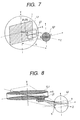
- FIG. 7 illustrates a perspective view of an optical system of an image projector in an image display of the Embodiment 1 according to the present invention.
- FIG. 1 illustrates a cross-sectional view of FIG. 7 in an x z plane.
- the image projector includes LED light sources 1 arranged in an array-like form, an illuminating lens L1, a transmittance type LCD panel 2T, and a projection lens L2.
- the light source includes a light emitting unit, i.e., the LED light sources 1, and the illuminating lens L1.
- the LED light sources 1 have a diffusion angle ⁇ LED toward an optical axis (i.e., z axis).
- the lens L1 which has a focal length f1 is located so that the distance between the lens L1 and an entrance pupil EP of the projection lens L2 becomes equal to the focal length f1.
- An area of the lens L1, i.e., an exit plane of the light sources, is larger than an area of the LCD panel 2T.
- the lens L1 and the LCD panel 2T are located in such a manner that an angle that a line forms with the lens L1 becomes an acute angle, the line connecting a circumference of the lens L1 with a circumference of the LCD panel 2T.
- the lights emitted from the respective points of the LED array light sources 1 with the angle ⁇ ⁇ LED are converged onto positions a, b on the entrance pupil EP by the exertion of the lens L1.
- a light passing through a position R (a light having image information on the position R) on the LCD panel 2T, as indicated by the sloped line portion in FIG. 7, has been extended over between the positions a, b on the entrance pupil EP.
- this light is emitted from portions of a width a', b' on an exit pupil EXP of the projection lens L2, then being converged onto a position R' on the directional reflection screen 3.
- the light distribution on the exit pupil EXP is in a corresponding relationship with that on the entrance pupil EP.
- the directional reflection screen 3 regarding the horizontal direction, has the function of reflecting a light into the incident direction.
- the light that has entered the position R' is reflected and extended again over between the positions a', b' on the exit pupil EXP.
- the above-described steps up to this are also the same concerning the positions other than the position R on the transmittance type LCD panel 2T.
- the directional reflection screen 3 regarding the vertical direction, has the function of diffusing and reflecting an incident light. Consequently, if a viewer (not illustrated) looks at the screen 3 with his or her eyes positioned directly above or below between the positions a', b' on the surface of the exit pupil EXP, the viewer is able to view the image within the range.
- a size of a human's pupil is about 10mm
- the range a b is longer than the diameter of the entrance pupil EP, it is possible to obtain the viewing area that is substantially the same as that in the ideal case although the light loss is increased. However, if the range a b is shorter than the diameter of the entrance pupil EP, the viewing area becomes narrower than that in the ideal case although there occurs no light loss.
- the present invention can also be implemented in the following case: A cylinder lens CL1 exhibiting a lens effect only in the horizontal direction is used as the illuminating lens, and the light having passed through the position R on the transmittance type LCD panel 2T is extended over only in the horizontal direction.
- the occasion is ideal where the light is diffused only in the horizontal direction with the angle ⁇ LED and is not diffused in the vertical direction.
- the present invention can be implemented even if there exists a diffused component in the vertical direction.
- the case where the reflection type LCD panel is used can be regarded as being equivalent to the case where the transmittance type LCD panel is used.
- HM half mirror
- the light source includes the cylinder lens CL1 and the light emitting unit, i.e., the LED array light sources 1
- the explanation will be given concerning the way in which lights travel in the vertical direction (a y-axis direction).
- the cylinder lens CL1 is located so that it converges or diverges lights perpendicular to the surface of the page on which FIG. 4 is illustrated, namely, it exhibits the lens effect in an x-axis direction.
- the half mirror HM is located so that it reflects a light entering in the vertical direction (the y-axis direction) into the horizontal direction (a z-axis direction), and thus the half mirror HM exerts no influence onto the vertical direction.
- a light emitted from the LED array light sources 1 located above is reflected into the z-axis direction by the half mirror HM, then entering the reflection type LCD panel 2R.
- the light reflected by the reflection type LCD panel 2R passes through the half mirror HM, then being guided into the projection lens L2. It is needless to say that a beam splitter may be used instead of the half mirror.
- ⁇ LED ⁇ 7 ⁇
- f1 40.7mm
- a horizontal direction size of LCD 2R 7.6mm
- the horizontal-direction lights-overlapped range a b on the entrance pupil 10mm
- a size of the LED array light sources 32.8mm ⁇ 27.3mm or 32.8mm ⁇ 7.6mm.
- FIG. 3 illustrates a horizontal direction cross-sectional view of an image projector in the Embodiment 2 according to the present invention.
- a halogen lamp is used as the light source.
- the halogen lamp has been used as the light source in the present embodiment
- the light source is not limited thereto.
- a metal halide lamp is also usable as the light source.
- the present embodiment is not only applicable to the case where the image of the filament H is formed on the entrance pupil EP by the ellipse mirror M but also applicable to the case where the image is formed by an illuminating lens.
- H 1.6mm
- f1 7.6mm
- s1 8.3mm
- s1' 94.9mm
- FIG. 5 is a top view of an image projector in the Embodiment 3 according to the present invention, the image projector having a diffuser 4 as a diffusing member.
- the lights are diffused at the respective positions of the diffuser 4.
- the diffusion angle of the diffuser at this time is assumed to be ⁇ d1 .
- the light passing through the position R on the transmittance type LCD panel 2T the light has been extended over in a range a, c that includes and is wider than the horizontal-direction lights-overlapped range a b on the entrance pupil.
- the lights passing through the other positions on the transmittance type LCD panel 2T have been extended over in ranges that include and are wider than the range a b.
- the implementation is possible by locating the diffuser so that all of the lights having passed through the transmittance type LCD panel 2T are similarly extended over in the ranges that include and are wider than the range a b.
- the diffusion angle ⁇ d2 of the diffuser 4 is allowed to be smaller than the above-described diffusion angle ⁇ d1 . This also results in a higher utilization efficiency of the lights.
- the diffuser 4 is also possible with the use of such diffusers as the one that diffuses a light in the horizontal direction strongly (i.e., a holographic device).
- the present embodiment is also applicable to the reflection type LCD panel.
- an incident light into the panel and the light reflected therefrom pass through the same optical path with each other. Accordingly, in order not to deteriorate the image information that the light reflected from the reflection type LCD panel has, it is required to bring the diffuser into close contact with the reflection type LCD panel.
- the same effect is also obtainable using a micro lens array as the diffusing member in the present embodiment.
- the above-described embodiments have been the ones concerning the image display including the image projector and the directional reflection screen. Meanwhile, as illustrated in FIG. 11, the present embodiment is also usable in the case where the LCD panel within the image projector 5 is directly viewed (i.e., for the wearable case). Even in this type of embodiment, the present invention makes it possible to extend the viewing area.
- the present invention permits a conventionally chipped image to be viewed in a state of being not chipped. In addition to this, the present invention makes it possible to extend even further the viewing area in the state.
Landscapes
- Engineering & Computer Science (AREA)
- Multimedia (AREA)
- Signal Processing (AREA)
- Physics & Mathematics (AREA)
- General Physics & Mathematics (AREA)
- Liquid Crystal (AREA)
- Devices For Indicating Variable Information By Combining Individual Elements (AREA)
Abstract
Description
- The present invention relates to an image projector and an image display that includes the image projector and a directional reflection screen.
- Conventionally, as the image display formed by combining the directional reflection screen with the image projector, there have been known apparatuses such as a 3-dimensional display using the principle of binocular parallax. The fundamental principle of the directional reflection screen that uses a corner reflective-mirror group as a light-converging method in the horizontal direction has been disclosed on, for example, page 28 and pp. 91-97 in Takayoshi Oukoshi, "Three Dimensional Image Engineering", Asakura Bookstore Press.
- FIG. 6 illustrates a directional reflection screen disclosed in JP-A-10-186522, which has been manufactured using the technology based on the above-described principle. Combining a 2-plane orthogonal corner reflective-
mirror group 31 with alenticular board 32 configures ascreen 3. Incident light into the screen is converged and reflected in the horizontal direction by the 2-plane orthogonal corner reflective-mirror group 31, and the incident light is diffused and reflected in the vertical direction by thelenticular board 32. - FIG. 9 illustrates the state where, when an image is projected onto the above-described
screen 3, the reflection of the light is seen from the above. Since the light reflected by thescreen 3 is converged onto the positions of twoimage projectors image projectors viewer 20, respectively. At the same time, a pair of image signals becoming a 3-dimensional image signal based on the principle of the binocular parallax is projected and irradiated onto thescreen 3. This operation allows theviewer 20 to view the 3-dimensional image. - Here, although the above-described explanation is about the 3-dimensional image, a 2-dimensional image can be viewed when projecting identical image signals from the two
image projectors 51, 52.- Also, it is needless to say that, when using only one image projector, the 2-dimensional image can also be viewed. - As is clear from the above-described prior art, a width in the horizontal direction of the light emitted from a projection lens in the image projector toward the screen is equal to a width in the horizontal direction where the viewer is able to view the image. Accordingly, if the image projector is downsized for implementing, for example, space-saving, the projection lens is also reduced in association therewith, thus narrowing the viewing area. In order not to narrow the viewing area, it is considered that the other optical systems in the image projector are downsized with only a size of the projection lens kept unchanged. In this consideration, however, the light is emitted from only a portion of range of the projection lens, resulting in no improvement in the viewing area.
- Preferably it is an object of the present invention to provide an image projector and an image display where the viewing area in the horizontal direction is extended.
- In order to solve the above-described problem, it is preferable and appropriate to extend lights in an entrance pupil of the projection lens in the image projector so that the lights are overlapped each other at least in the horizontal direction, the lights having passed through or reflected from the respective positions on the LCD panel.
- Here, the phrase "the respective positions on the LCD panel" means the respective pixels of the LCD panel. The phrase "having passed through or reflected from" means that the LCD panel is of "a transmittance type or a reflection type". The phrase "are overlapped each other in the horizontal direction" means that, when the extended states of the lights into the horizontal direction are compared with each other in the entrance pupil of the projection lens, the lights attaining from the respective pixels exist in a certain range in the horizontal direction, the lights having passed through or reflected from the respective positions on the LCD panel. The phrase "are overlapped each other at least in the horizontal direction" means that the lights existing in this range include states of being located apart from each other in the vertical direction. The lights, of course, include states of being overlapped each other not only in the horizontal direction but also in the vertical direction. The phrases "the horizontal direction and the vertical direction" correspond to "the horizontal direction and the vertical direction" used usually in the directional reflection screen illustrated in FIG. 6. In the directional reflection screen, a direction obtained by connecting the both eyes of the viewer is "the horizontal direction".
- When the lights in these states are emitted from the image projector and enter the directional reflection screen, even in the case of the lights existing in the states of being located apart from each other in the vertical direction, the lights that have been reflected by the directional reflection screen and have returned back to an exit pupil of the projection lens are overlapped each other in the vertical direction. This is attributed to the fact that the directional reflection screen has the function of diffusing and reflecting the incident light in the vertical direction. Also, the lights that have returned back to the exit pupil, in the horizontal direction, are overlapped each other in a range that is equal to the range at the time of the emission from the exit pupil. Consequently, the exit pupil is located directly above or below the viewer, thereby allowing the viewer to view an image without being chipped.
- As having been described so far, in summary, the image projector in the present invention is characterized by including a light source, the LCD panel that the lights emitted from the light source enter, and the projection lens that the lights emitted from the LCD panel enter, wherein there exists, in the entrance pupil of the projection lens, a range in which the lights emitted from the respective pixels of the LCD panel are overlapped each other at least in the horizontal direction. The LCD panel may be of either the transmittance type or the reflection type.
- Also, the image display in the present invention is characterized by being formed by locating the image projector and the directional reflection screen in such a manner as to be in parallel to the horizontal direction.
- The present invention permits a conventionally chipped image to be viewed in a state of being not chipped. In addition to this, the present invention makes it possible to extend further the viewing area in the state.
-
- FIG. 1 is a horizontal direction cross-sectional view of an optical system of an image projector in an embodiment according to the present invention;
- FIG. 2 is a top view of the image display in the embodiment according to the present invention;
- FIG. 3 is a horizontal direction cross-sectional view of an optical system of an image projector in an embodiment according to the present invention;
- FIG. 4 is a vertical direction cross-sectional view of an optical system of an image projector in an embodiment according to the present invention;
- FIG. 5 is a horizontal direction cross-sectional view of an image projector in an embodiment according to the present invention;
- FIG. 6 is a perspective view for illustrating the structure of the directional reflection screen;
- FIG. 7 is a perspective view of the optical system of the image display in the embodiment according to the present invention;
- FIG. 8 is a perspective view of an optical system of an image display in an embodiment according to the present invention;
- FIG. 9 is a top view of the image display according to the prior art;
- FIG. 10 is a horizontal direction cross-sectional view of the optical system of the image projector in the embodiment according to the present invention; and
- FIG. 11 is a side view of an embodiment of the image display according to the present invention.
-
- Hereinafter, using the embodiments, the explanation will be given concerning the details of the present invention. The image projector is defined as an apparatus (projector) that includes at least a light source, a LCD panel, and a projection lens. Also, the image display is defined as an apparatus that includes the image projector and a directional reflection screen.
- FIG. 7 illustrates a perspective view of an optical system of an image projector in an image display of the
Embodiment 1 according to the present invention. FIG. 1 illustrates a cross-sectional view of FIG. 7 in an x z plane. The image projector includesLED light sources 1 arranged in an array-like form, an illuminating lens L1, a transmittancetype LCD panel 2T, and a projection lens L2. In the present embodiment, the light source includes a light emitting unit, i.e., theLED light sources 1, and the illuminating lens L1. - The
LED light sources 1 have a diffusion angle LED toward an optical axis (i.e., z axis). The lens L1, which has a focal length f1, is located so that the distance between the lens L1 and an entrance pupil EP of the projection lens L2 becomes equal to the focal length f1. An area of the lens L1, i.e., an exit plane of the light sources, is larger than an area of theLCD panel 2T. The lens L1 and theLCD panel 2T are located in such a manner that an angle that a line forms with the lens L1 becomes an acute angle, the line connecting a circumference of the lens L1 with a circumference of theLCD panel 2T. On account of this location, the lights emitted from the respective points of the LEDarray light sources 1 with the angle ± LED are converged onto positions a, b on the entrance pupil EP by the exertion of the lens L1. At this time, a light passing through a position R (a light having image information on the position R) on theLCD panel 2T, as indicated by the sloped line portion in FIG. 7, has been extended over between the positions a, b on the entrance pupil EP. Namely, there exists, in the entrance pupil, a lights-overlapped range a b in the horizontal direction. - As illustrated in FIG. 2, this light is emitted from portions of a width a', b' on an exit pupil EXP of the projection lens L2, then being converged onto a position R' on the
directional reflection screen 3. Here, the light distribution on the exit pupil EXP is in a corresponding relationship with that on the entrance pupil EP. Thedirectional reflection screen 3, regarding the horizontal direction, has the function of reflecting a light into the incident direction. On account of this, the light that has entered the position R' is reflected and extended again over between the positions a', b' on the exit pupil EXP. The above-described steps up to this are also the same concerning the positions other than the position R on the transmittancetype LCD panel 2T. As a result, all the image information on the transmittancetype LCD panel 2T exists between the positions a', b' on the exit pupil EXP. Thedirectional reflection screen 3, regarding the vertical direction, has the function of diffusing and reflecting an incident light. Consequently, if a viewer (not illustrated) looks at thescreen 3 with his or her eyes positioned directly above or below between the positions a', b' on the surface of the exit pupil EXP, the viewer is able to view the image within the range. Considering the fact that a size of a human's pupil is about 10mm, in order to provide an image that the viewer finds it easy to see, it is preferable that there exists 10mm or longer lights-overlapped range a' b' on the surface of the exit pupil EXP. It is preferable that there also exists the 10mm or longer lights-overlapped range a b on the surface of the entrance pupil EP. - Also, considering the utilization efficiency of the lights, it is ideal that, as illustrated in FIG. 1, the lights-overlapped range a b is of the same length as that of the diameter of the entrance pupil EP, namely, the relationship given by the following
formula 1 holds:
[formula 1] - Here, even if the range a b is longer than the diameter of the entrance pupil EP, it is possible to obtain the viewing area that is substantially the same as that in the ideal case although the light loss is increased. However, if the range a b is shorter than the diameter of the entrance pupil EP, the viewing area becomes narrower than that in the ideal case although there occurs no light loss.
- The above-described explanation has been given regarding the case where the transmittance lights from the respective pixels of the LCD panel have been extended over the entire surface of the entrance pupil EP.
- Meanwhile, as illustrated in FIG. 8, the present invention can also be implemented in the following case: A cylinder lens CL1 exhibiting a lens effect only in the horizontal direction is used as the illuminating lens, and the light having passed through the position R on the transmittance
type LCD panel 2T is extended over only in the horizontal direction. Considering the utilization efficiency of the light in this case, the occasion is ideal where the light is diffused only in the horizontal direction with the angle LED and is not diffused in the vertical direction. The present invention, however, can be implemented even if there exists a diffused component in the vertical direction. - Also, from an optical point of view, the case where the reflection type LCD panel is used can be regarded as being equivalent to the case where the transmittance type LCD panel is used. In this case, however, it is required to use a half mirror (HM) as is indicated in a cross-sectional view of an image projector illustrated in FIG. 4.
- Hereinafter, in the image projector where the light source includes the cylinder lens CL1 and the light emitting unit, i.e., the LED array
light sources 1, the explanation will be given concerning the way in which lights travel in the vertical direction (a y-axis direction). The cylinder lens CL1 is located so that it converges or diverges lights perpendicular to the surface of the page on which FIG. 4 is illustrated, namely, it exhibits the lens effect in an x-axis direction. Also, the half mirror HM is located so that it reflects a light entering in the vertical direction (the y-axis direction) into the horizontal direction (a z-axis direction), and thus the half mirror HM exerts no influence onto the vertical direction. - On account of this, a light emitted from the LED array
light sources 1 located above is reflected into the z-axis direction by the half mirror HM, then entering the reflectiontype LCD panel 2R. The light reflected by the reflectiontype LCD panel 2R passes through the half mirror HM, then being guided into the projection lens L2. It is needless to say that a beam splitter may be used instead of the half mirror. - In the present embodiment, the following numerical values have been employed: LED = ±7·, f1 = 40.7mm, a horizontal direction size of
LCD 2R = 7.6mm, the horizontal-direction lights-overlapped range a b on the entrance pupil = 10mm, and, a size of the LED array light sources = 32.8mm × 27.3mm or 32.8mm × 7.6mm. - FIG. 3 illustrates a horizontal direction cross-sectional view of an image projector in the Embodiment 2 according to the present invention. A halogen lamp is used as the light source. Moreover, an illuminating ellipse mirror M forms an image of a filament H of the halogen lamp on the surface of the entrance pupil EP of the projection lens L2. Namely, the following formula 2 is satisfied:
[formula 2] - Images of all the lights emitted from Ha on the filament H and then reflected by the ellipse mirror M are formed onto b on the surface of the entrance pupil EP. Similarly, images of all the lights emitted from Hb and then reflected by the ellipse mirror M are formed onto a. At this time, the light passing through the position R (the light having the image information on the position R) on the transmittance
type LCD panel 2T, as indicated by the sloped line portion in FIG. 3, has been extended over between the positions a, b on the entrance pupil EP. Namely, there exists the horizontal-direction lights-overlapped range a b on the entrance pupil. Concerning the way in which the lights will travel thereinafter, the viewing area and the utilization efficiency of the lights, they are substantially the same as those in theEmbodiment 1. - Although the halogen lamp has been used as the light source in the present embodiment, the light source is not limited thereto. For example, a metal halide lamp is also usable as the light source. Also, it is needless to say that the present embodiment is not only applicable to the case where the image of the filament H is formed on the entrance pupil EP by the ellipse mirror M but also applicable to the case where the image is formed by an illuminating lens.
- In the present embodiment, the following numerical values have been employed: H = 1.6mm, f1 = 7.6mm, s1 = 8.3mm, and, s1' = 94.9mm.
- FIG. 5 is a top view of an image projector in the
Embodiment 3 according to the present invention, the image projector having a diffuser 4 as a diffusing member. When parallel lights enter the diffuser 4, the lights are diffused at the respective positions of the diffuser 4. (The diffusion angle of the diffuser at this time is assumed to be d1.) Here, paying attention to the light passing through the position R on the transmittancetype LCD panel 2T, the light has been extended over in a range a, c that includes and is wider than the horizontal-direction lights-overlapped range a b on the entrance pupil. Similarly, the lights passing through the other positions on the transmittancetype LCD panel 2T have been extended over in ranges that include and are wider than the range a b. In general, a light having entered the range a b on the entrance pupil EP is emitted from the range a' b' on the exit pupil EXP. Consequently, with the help of the functions of the directional reflection screen described earlier, it becomes possible to view an image in the range a' b'. - Also, when the incident lights into the diffuser 4 are no parallel lights, the implementation is possible by locating the diffuser so that all of the lights having passed through the transmittance
type LCD panel 2T are similarly extended over in the ranges that include and are wider than the range a b. For example, as illustrated in FIG. 10, if the lights that are going to converge into the center of the entrance pupil EP enter the diffuser 4, the diffusion angle d2 of the diffuser 4 is allowed to be smaller than the above-described diffusion angle d1. This also results in a higher utilization efficiency of the lights. - Furthermore, implementing the diffuser 4 is also possible with the use of such diffusers as the one that diffuses a light in the horizontal direction strongly (i.e., a holographic device).
- Although the above-described explanation concerning the present embodiment has been the one based on the transmittance type LCD panel, the present embodiment is also applicable to the reflection type LCD panel. In an optical system using the reflection type LCD panel, an incident light into the panel and the light reflected therefrom pass through the same optical path with each other. Accordingly, in order not to deteriorate the image information that the light reflected from the reflection type LCD panel has, it is required to bring the diffuser into close contact with the reflection type LCD panel. The same effect is also obtainable using a micro lens array as the diffusing member in the present embodiment.
- The above-described embodiments have been the ones concerning the image display including the image projector and the directional reflection screen. Meanwhile, as illustrated in FIG. 11, the present embodiment is also usable in the case where the LCD panel within the
image projector 5 is directly viewed (i.e., for the wearable case). Even in this type of embodiment, the present invention makes it possible to extend the viewing area. - The present invention permits a conventionally chipped image to be viewed in a state of being not chipped. In addition to this, the present invention makes it possible to extend even further the viewing area in the state.
Claims (20)
- An image projector (5), comprising:a light source (1),a LCD panel (2T) that a light emitted from said light source (1) enter, anda projection lens (L2) that said light emitted from said LCD panel (2T) enter, wherein there exists, in an entrance pupil (EP) of said projection lens (L2), a range in which lights emitted from respective pixels of said LCD panel (2T) are overlapped each other at least in a horizontal direction.
- The image projector (5) as claimed in Claim 1, wherein there exists 10mm or longer of said range in which said lights are overlapped in said horizontal direction.
- The image projector (5) as claimed in Claim 1, wherein said light source (1) includes a cylinder lens (CL1) on the side of said LCD panel (2T).
- The image projector (5) as claimed in Claim 1, wherein said light source (1) includes a LED array light source (1).
- The image projector (5) as claimed in Claim 1, wherein said light source (1) includes diffusing means on the side of said LCD panel (2T).
- The image projector (5) as claimed in Claim 5, wherein said diffusing means is a micro lens.
- The image projector (5) as claimed in Claim 1, wherein said LCD panel is a reflection type LCD panel (2R), said light source (1) being located at a position off from an axis that connects said reflection type LCD panel (2R) with said projection lens (L2), said image projector (5) further comprising a half mirror (HM) or a beam splitter, said half mirror (HM) or said beam splitter reflecting said light emitted from said light source (1) so as to cause said light to enter said reflection type LCD panel (2R) and permitting said light reflected by said reflection type LCD panel (2R) to pass through so as to cause said light to enter said projection lens (L2).
- An image projector (5), comprising:a light source (1),a LCD panel (2T) that a light emitted from said light source (1) enter, anda projection lens (L2) that said light emitted from said LCD panel (2T) enter, wherein an area of an exit plane of said light source (1) is larger than an area of said LCD panel (2T), said light source (1) and said LCD panel (2T) being located so that an angle formed between a line and said exit plane of said light source (1) becomes an acute angle, said line connecting a circumference of said exit plane of said light source (1) with a circumference of said LCD panel (2T).
- The image projector (5) as claimed in Claim 8, wherein there exists, in an exit pupil (EXP) of said projection lens (L2), a range in which lights emitted from the respective pixels of said LCD panel (2T) are overlapped each other at least in a horizontal direction, and there exists 10mm or longer of said lights-overlapped range.
- An image display, comprising:said image projector (5) as claimed in Claim 1, anda directional reflection screen (3) for reflecting a light emitted from said image projector (5), wherein said image projector (5) and said directional reflection screen (3) are located in such a manner as to be in parallel to said horizontal direction.
- An image display, comprising:said image projector (5) as claimed in Claim 2, anda directional reflection screen (3) for reflecting a light emitted from said image projector (5), wherein said image projector (5) and said directional reflection screen (3) are located in such a manner as to be in parallel to said horizontal direction.
- An image display, comprising:said image projector (5) as claimed in Claim 3, anda directional reflection screen (3) for reflecting a light emitted from said image projector (5), wherein said image projector (5) and said directional reflection screen (3) are located in such a manner as to be in parallel to said horizontal direction.
- An image display, comprising:said image projector (5) as claimed in Claim 4, anda directional reflection screen (3) for reflecting a light emitted from said image projector (5), wherein said image projector (5) and said directional reflection screen (3) are located in such a manner as to be in parallel to said horizontal direction.
- An image display, comprising:said image projector (5) as claimed in Claim 5, anda directional reflection screen (3) for reflecting a light emitted from said image projector (5), wherein said image projector (5) and said directional reflection screen (3) are located in such a manner as to be in parallel to said horizontal direction.
- An image display, comprising:said image projector (5) as claimed in Claim 6, anda directional reflection screen (3) for reflecting a light emitted from said image projector (5), wherein said image projector (5) and said directional reflection screen (3) are located in such a manner as to be in parallel to said horizontal direction.
- An image display, comprising:said image projector (5) as claimed in Claim 7, anda directional reflection screen (3) for reflecting a light emitted from said image projector (5), wherein said image projector (5) and said directional reflection screen (3) are located in such a manner as to be in parallel to said horizontal direction.
- An image display, comprising:said image projector (5) as claimed in Claim 8, anda directional reflection screen (3) for reflecting a light emitted from said image projector (5), wherein said image projector (5) and said directional reflection screen (3) are located in such a manner as to be in parallel to said horizontal direction.
- An image display, comprising:said image projector (5) as claimed in Claim 9, anda directional reflection screen (3) for reflecting a light emitted from said image projector (5), wherein said image projector (5) and said directional reflection screen (3) are located in such a manner as to be in parallel to said horizontal direction.
- The image display as claimed in Claim 10, wherein there are provided two of said image projectors (51), (52).
- The image display as claimed in Claim 17, wherein there are provided two of said image projectors (51), (52).
Applications Claiming Priority (2)
| Application Number | Priority Date | Filing Date | Title |
|---|---|---|---|
| JP25672099 | 1999-09-10 | ||
| JP25672099 | 1999-09-10 |
Publications (2)
| Publication Number | Publication Date |
|---|---|
| EP1083747A2 true EP1083747A2 (en) | 2001-03-14 |
| EP1083747A3 EP1083747A3 (en) | 2002-10-30 |
Family
ID=17296528
Family Applications (1)
| Application Number | Title | Priority Date | Filing Date |
|---|---|---|---|
| EP00307754A Withdrawn EP1083747A3 (en) | 1999-09-10 | 2000-09-08 | Projector and display system |
Country Status (2)
| Country | Link |
|---|---|
| US (1) | US6513933B1 (en) |
| EP (1) | EP1083747A3 (en) |
Families Citing this family (2)
| Publication number | Priority date | Publication date | Assignee | Title |
|---|---|---|---|---|
| WO2007072358A2 (en) * | 2005-12-20 | 2007-06-28 | Koninklijke Philips Electronics, N.V. | Method and apparatus for correcting misalignment of a lenticular in a 3-d television receiver |
| DE102010022383A1 (en) * | 2010-06-01 | 2011-12-01 | Erco Gmbh | projector |
Family Cites Families (15)
| Publication number | Priority date | Publication date | Assignee | Title |
|---|---|---|---|---|
| US5900982A (en) * | 1987-12-31 | 1999-05-04 | Projectavision, Inc. | High efficiency light valve projection system |
| FR2707447B1 (en) * | 1993-07-09 | 1995-09-01 | Thomson Csf | Color display device. |
| US5398125A (en) * | 1993-11-10 | 1995-03-14 | Minnesota Mining And Manufacturing Company | Liquid crystal projection panel having microlens arrays, on each side of the liquid crystal, with a focus beyond the liquid crystal |
| GB2284068A (en) * | 1993-11-12 | 1995-05-24 | Sharp Kk | Three-dimensional projection display apparatus |
| US5622418A (en) * | 1994-03-29 | 1997-04-22 | Mitsubishi Denki Kabuskiki Kaisha | Projection display device |
| JPH086023A (en) * | 1994-04-22 | 1996-01-12 | Matsushita Electric Ind Co Ltd | Liquid crystal display device and liquid crystal projection device |
| GB2297389A (en) * | 1995-01-28 | 1996-07-31 | Sharp Kk | Three dimensional display having autostereoscopic and stereoscopic modes |
| KR19980028035A (en) * | 1995-10-25 | 1998-07-15 | 윌리엄 이. 힐러 | Lighting system for hard copy devices |
| JPH09182112A (en) * | 1995-12-22 | 1997-07-11 | Sharp Corp | Projector device using small optical system |
| JP3195238B2 (en) * | 1996-06-18 | 2001-08-06 | シャープ株式会社 | Projection type color liquid crystal display |
| US5795049A (en) * | 1996-08-27 | 1998-08-18 | In Focus Systems, Inc. | Image projection system |
| GB2317524A (en) * | 1996-09-19 | 1998-03-25 | Sharp Kk | Three dimensional stereoscopic projection display |
| JP3526157B2 (en) * | 1996-12-24 | 2004-05-10 | 株式会社日立製作所 | Directional reflective screen and image display device |
| JP3630906B2 (en) * | 1997-02-18 | 2005-03-23 | キヤノン株式会社 | Stereoscopic image display device |
| JP4258071B2 (en) * | 1999-08-04 | 2009-04-30 | コニカミノルタホールディングス株式会社 | Video display device |
-
2000
- 2000-09-08 US US09/658,485 patent/US6513933B1/en not_active Expired - Lifetime
- 2000-09-08 EP EP00307754A patent/EP1083747A3/en not_active Withdrawn
Non-Patent Citations (1)
| Title |
|---|
| None |
Also Published As
| Publication number | Publication date |
|---|---|
| EP1083747A3 (en) | 2002-10-30 |
| US6513933B1 (en) | 2003-02-04 |
Similar Documents
| Publication | Publication Date | Title |
|---|---|---|
| KR100388819B1 (en) | Optical System for Head Mount Display | |
| US7144113B2 (en) | Virtual image display apparatus | |
| KR100386725B1 (en) | Optical System for Head Mount Display | |
| KR890017486A (en) | Lighting system | |
| EP0603583A1 (en) | Image projection apparatus | |
| US3944351A (en) | Apparatus for superimposing a plurality of images | |
| US6783249B2 (en) | Projection-type image display device | |
| WO2020261830A1 (en) | Head-up display device | |
| JP2001108939A5 (en) | ||
| US6513933B1 (en) | Projector and display system | |
| JP3658246B2 (en) | Image display device and image projection device | |
| JP7111070B2 (en) | head-up display device | |
| JP2019045605A (en) | Head-up display device | |
| US6873470B2 (en) | Arrangement for the visualization of information in a motor vehicle | |
| JP3301321B2 (en) | Illumination optical system device and projection display device | |
| JP2004133181A (en) | Vehicle split display device | |
| KR100354149B1 (en) | Optical System for Head Mount Display | |
| US6705730B2 (en) | Picture display device | |
| JPH1138360A (en) | Stereoscopic image reproducing method, stereoscopic image reproducing apparatus, and directional reflection screen | |
| JP7111071B2 (en) | head-up display device | |
| JPH0618810A (en) | Display device | |
| JP2004309765A (en) | Reflection optical system and projection device using the same | |
| JP2004234006A (en) | Microscope having illumination system | |
| JP2001147488A (en) | Image projection device and image display device | |
| JP2551002B2 (en) | Lighting device having elliptical mirror |
Legal Events
| Date | Code | Title | Description |
|---|---|---|---|
| PUAI | Public reference made under article 153(3) epc to a published international application that has entered the european phase |
Free format text: ORIGINAL CODE: 0009012 |
|
| AK | Designated contracting states |
Kind code of ref document: A2 Designated state(s): AT BE CH CY DE DK ES FI FR GB GR IE IT LI LU MC NL PT SE |
|
| AX | Request for extension of the european patent |
Free format text: AL;LT;LV;MK;RO;SI |
|
| PUAL | Search report despatched |
Free format text: ORIGINAL CODE: 0009013 |
|
| AK | Designated contracting states |
Kind code of ref document: A3 Designated state(s): AT BE CH CY DE DK ES FI FR GB GR IE IT LI LU MC NL PT SE |
|
| AX | Request for extension of the european patent |
Free format text: AL;LT;LV;MK;RO;SI |
|
| 17P | Request for examination filed |
Effective date: 20021217 |
|
| AKX | Designation fees paid |
Designated state(s): DE GB |
|
| 17Q | First examination report despatched |
Effective date: 20030917 |
|
| STAA | Information on the status of an ep patent application or granted ep patent |
Free format text: STATUS: THE APPLICATION IS DEEMED TO BE WITHDRAWN |
|
| 18D | Application deemed to be withdrawn |
Effective date: 20100806 |