EP1083711A2 - ATM protection switching method and apparatus - Google Patents
ATM protection switching method and apparatus Download PDFInfo
- Publication number
- EP1083711A2 EP1083711A2 EP00307794A EP00307794A EP1083711A2 EP 1083711 A2 EP1083711 A2 EP 1083711A2 EP 00307794 A EP00307794 A EP 00307794A EP 00307794 A EP00307794 A EP 00307794A EP 1083711 A2 EP1083711 A2 EP 1083711A2
- Authority
- EP
- European Patent Office
- Prior art keywords
- atm
- network
- entity
- cells
- signal degrade
- Prior art date
- Legal status (The legal status is an assumption and is not a legal conclusion. Google has not performed a legal analysis and makes no representation as to the accuracy of the status listed.)
- Withdrawn
Links
Images


Classifications
-
- H—ELECTRICITY
- H04—ELECTRIC COMMUNICATION TECHNIQUE
- H04Q—SELECTING
- H04Q11/00—Selecting arrangements for multiplex systems
- H04Q11/04—Selecting arrangements for multiplex systems for time-division multiplexing
- H04Q11/0428—Integrated services digital network, i.e. systems for transmission of different types of digitised signals, e.g. speech, data, telecentral, television signals
- H04Q11/0478—Provisions for broadband connections
-
- H—ELECTRICITY
- H04—ELECTRIC COMMUNICATION TECHNIQUE
- H04J—MULTIPLEX COMMUNICATION
- H04J2203/00—Aspects of optical multiplex systems other than those covered by H04J14/05 and H04J14/07
- H04J2203/0001—Provisions for broadband connections in integrated services digital network using frames of the Optical Transport Network [OTN] or using synchronous transfer mode [STM], e.g. SONET, SDH
- H04J2203/0057—Operations, administration and maintenance [OAM]
- H04J2203/006—Fault tolerance and recovery
-
- H—ELECTRICITY
- H04—ELECTRIC COMMUNICATION TECHNIQUE
- H04L—TRANSMISSION OF DIGITAL INFORMATION, e.g. TELEGRAPHIC COMMUNICATION
- H04L12/00—Data switching networks
- H04L12/54—Store-and-forward switching systems
- H04L12/56—Packet switching systems
- H04L12/5601—Transfer mode dependent, e.g. ATM
- H04L2012/5625—Operations, administration and maintenance [OAM]
- H04L2012/5627—Fault tolerance and recovery
Definitions
- the present invention relates to asynchronous transfer mode ("ATM") networks, and more particularly to a method and apparatus for detecting and reacting to defects on such a network.
- ATM asynchronous transfer mode
- Synchronous optical networks For example, detect network defects and switch the routing of traffic within the network along differing physical paths in the presence of a defect to ensure data traffic delivery between end points. Such switching is typically referred to as "protection switching”.
- Modern ATM networks as for example detailed in International Telecommunication Union Recommendations ITU-T 1.326, I.610, I.630, and I.732, the contents of all of which are hereby incorporated by reference, support similar protection switching in the presence of defects to provide a signal across the network in the presence of signal failure (signal fail - "SF"), or in the presence of a degraded signal (signal degrade - "SD").
- SF is often manifested in loss of frames (LOF); loss of signal (LOS); or loss of cell delineation (LCD) at the physical layer carrying ATM traffic.
- LEF loss of frames
- LOS loss of signal
- LCD loss of cell delineation
- ITU-T Recommendation I.630 suggests that a SF may be detected at the physical layer.
- SD typically manifests itself in the presence of bit errors within the ATM signal.
- ITU-T Recommendation I.630 suggests detecting SD at the ATM layer, by using performance monitoring ("PM”) flows.
- PM
- the ATM layer relies upon the existing physical layer, faults detected at the ATM layer of the network are often detected some time after the same fault manifests itself at the physical layer. As such, the ATM layer is currently unable to detect and react to a SD condition as quickly as the physical layer might detect signs of the SD.
- signal degrade on an ATM network is detected by monitoring signal degrade at the physical layer of the network.
- ATM OAM cells indicative of the signal degrade may be generated at the ATM layer, and protection switching may be effected.
- signal degrade at the physical layer may be monitored by determining a bit-error-rate at the physical layer.
- ATM alarm indication signal (“AIS") cells or ATM protection switching coordination protocol (“CP”) cells may be generated to effect the protection switching.
- a network element for use in an ATM network in which ATM traffic is carried on a physical network adhering to a physical layer protocol, is operable to switch traffic transported on a working entity of the ATM network to a protection entity on the ATM network.
- the network element includes a detector for monitoring an indicator of signal degrade of the working entity provided by said physical layer protocol.
- Software may adapt an ATM network element to perform in accordance with the invention.
- FIG. 1 illustrates ATM NEs 12a, 12b (collectively, or individually 12 ) forming part of an ATM network, and exemplary of embodiments of the present invention.
- this ATM network will be formed upon a physical network, adhering to a physical layer protocol.
- This physical network may for example, be a Synchronous Optical Network (SONET), as it is called in North America, or its European counterpart, a Synchronous Digital Hierarchy (SDH). It may also be a DSn based telephony network, adhering, for example to ITU Recommendation G.707.
- SONET Synchronous Optical Network
- SDH Synchronous Digital Hierarchy
- NEs 12 may be conventional ATM switches. NEs 12 may be end nodes with which traffic originates on the ATM network, or intermediate nodes connected between end nodes. As illustrated, NEs 12 are connected by at least two links (hereafter referred to as "entities") 14 and 16 capable of transporting payload traffic between NEs 12a and 12b . As will become apparent, third and fourth links 18 and 19 used to carry out-of band signaling messages may further connect NEs 12 . Entities 14 and 16 and link 18 may directly connect NEs 12a and 12b , or alternatively couple NEs 12a and 12b by way of intermediate NEs (not illustrated). For simplicity of illustration, entities 14 and 16 and links 18 and 19 are illustrated as bi-directional links.
- Each entity 14 or 16 , and links 18 or 19 is intended to represent two unidirectional links, with one carrying traffic from NE 12a to NE 12b , and the other from NE 12b to NE 12a .
- each unidirectional link may be logically and physically separate from another associated unidirectional link.
- NEs 12 exchange communications traffic in accordance with known ATM protocols. Specifically, prior to the exchange of payload traffic one or more virtual circuits, for the exchange of payload data is negotiated between end NEs on the network. Each virtual circuit is made up of a series of virtual channels ("VC"s) carried on physical connections between nodes on the networks. For illustration, each entity 14, 16 and link 18, 19 is intended to represent a VC, between nodes 12a and 12b . As will be appreciated, entities 14 and 16 could alternatively represent virtual paths ("VP"s) carrying multiple channels between nodes 12a and 12b . Preferably entities 14 and 16 are physically as well as logically separate. However, as will be appreciated, any two or more of entities 14, 16 and links 18 and 20 may follow the same physical path between NEs 12 .
- VC virtual channels
- Traffic is exchanged between NEs 12 in packets.
- Each packet has fifty-three bytes and is known as a "cell".
- Each cell includes a five byte header.
- the cell header includes a payload type identifier ("PTI"), a virtual channel identifier (“VCI”) associated with the cell, and a virtual path identifier ("VPI").
- the VPI identifies a path between two nodes, while a VCI identifies a channel along such a path. All traffic passing from NEs 12a to 12b associated with a particular virtual circuit is transported on a virtual channel ("VC") between NEs 12a and 12b .
- VC virtual channel
- the VC may be uniquely identified by a VPI/VCI pair contained in cells transferred between NEs 12a and 12b .
- a routing table maintained at NE 12a allows NEs 12a to switch all traffic arriving at the input of NE 12a in one VC to another VC associated with a unique VPI/VCI pair at the output of NE 12a .
- NE 12b switches cells associated in a VC at the input of NE 12b to a single VC associated with a unique VPI/VCI pair at the output of NE 12b . Thereby all cells associated with a virtual circuit are routed along a defined route along the network.
- a virtual circuit between end-nodes on an ATM network is thus identified by a series of VPI/VCI pairs, across the network.
- a secondary channel may also be negotiated between NEs 12a and 12b .
- a primary channel is typically referred to as a working channel.
- secondary channels may negotiate for a virtual circuit across the network, or for a portion of a virtual circuit across the network.
- a secondary channel is often referred to as a protection channel or entity, and may be used to carry traffic normally transported by a working channel, in the event of a defect.
- ITU-T Recommendation 1.630 details ATM layer protection switching, from a working channel to a protection channel, performed in response to the detection of certain defects.
- Such protection switching at the ATM layer should avoid contentions between any protection switching available at the physical layer of the network.
- SONET protection switching is disabled in order to avoid such contention.
- Protection switching may be supported for a single VC (i.e. a single VPI/VCI pair) between two nodes ("VC protection switching"); or for all VCs within a virtual path ("VP protection switching").
- VPG virtual path or virtual channel groups
- VCG virtual path or virtual channel groups
- entity 16 is intended to represent a protection channel for working entity 14 .
- OAM cells are identified by the values of the PTI or VCI fields of the header.
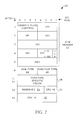
- a generic OAM cell 20 is illustrated in FIG. 2 . As illustrated OAM cells include a five byte ATM header 22 ; a four bit OAM type field 24; a four bit OAM function type field 26 ; forty-five bytes of function specific fields 28 ; six reserved bits 30 ; and a ten bit cyclic redundancy check field 32 .
- OAM cells specific to a VC may be identified by a PTI field value (binary) of 100 (4) or 101 (5).
- Sequential VC specific OAM cells passed within a VP or VC are referred to as F4 or F5 flows.
- F4 and F5 flows are carried in band for a specific channel and are identified by the VC's VPI/VCI pair contained in the OAM cell header 22 .
- OAM cells specific to an entire VP are identified by VCI value of 3 or 4.
- VP specific OAM cells are carried in band for a specific VP identified by its VPI contained in the OAM cell header.
- Protection switching i.e. the switching of traffic from a working ATM entity to a protection entity, is accomplished through the exchange of OAM cells generated in response to certain sensed conditions.
- OAM cells may be transported in-band along an affected VP or VC, and are identified by VPI/VCI pairs identical to the protected VC.
- a dedicated out-of-band OAM channel used for protection switching may be provisioned and associated with a group of VPs or VCs.
- This dedicated OAM channel acts as a signaling channel and is referred to as an OAM ATM Protection Switching ("APS") channel, and is identified between NEs by its own unique VPI/VCI pair.
- APS OAM ATM Protection Switching
- links 18 and 19 may each carry an APS channel.
- Link 18 carries an APS channel associated with entity 14 ; link 19 carries and APS channel associated with entity 16 .
- OAM cells may be generated and inserted into a stream of ATM cells by any element of the ATM network, including NEs 12 .
- the NEs affected by the fault may exchange OAM cells, known as Virtual Path - Alarm Indication Signal ("VP-AIS") cells or Virtual Circuit - Alarm Indication Signal (“VC-AIS”) cells and Remote Defect Indicator (“RDI”) cells.
- OAM cells as illustrated in FIG. 2 , are specifically identified as AIS cells by OAM type value of 0001 (binary) contained in field 24 , and a function type of 0000 (binary) contained in field 26 .
- OAM AIS cells are generated and sent downstream within an affected VP or VC at fixed intervals by a source NE, indicating a defect in the channel or path. Typically one AIS cell is sent each second.
- an AIS state is declared in response to receiving an AIS cell.
- the sink NE in response, sends RDI cells upstream to the source NE.
- RDI cells have the same format as AIS cells, with the exception of a function type of 0001 contained in field 26 ( FIG. 2 ).
- the source NE assumes an RDI state.
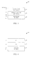
- the function specific fields 28 of AIS/RDI cells are illustrated in FIG. 3 . As illustrated the first byte of field 28 contains an optional one byte defect type field 34 ; a sixteen byte defect location field 36 ; and a twenty-eight reserved byte field 38 , typically filled with bytes having a value of 6A (Hex).
- the sink NE In 1+1 or 1:1 protection switching, the sink NE begins to use data received on the protection entity, immediately upon receipt of an AIS cell. In 1:1 protection switching, the source NE only begins to send traffic on the protection entity upon receipt of a CP cell. Upon receipt, the protection entity will be used to transport traffic between the source and sink NEs.
- ITU-T Recommendation I. 630 defines the use of APS coordination protocol ("CP") cells to effect ATM protection switching.
- the format of function specific fields 28 for CP cells is illustrated in FIG. 4 . As illustrated fields 28 are characterized by two one byte K1 and K2 fields 40 and 42 , followed by forty-three unused byte field 44 , preferably populated with bytes having a value of 6A (Hex).
- CP cells unlike AIS cells, may be passed in-band within a VC without loss of traffic. Alternatively, CP cells may be passed within an APS channel associated with a VPG or VPC. As detailed in ITU-T Recommendation I.630, CP cells are preferably generated and transmitted periodically, at five second intervals. Values of K1, K2 in fields 40 and 42 indicate the current perceived state of an entity at an NE. Thus, CP cells may signify that an NE has detected a defect within a VP or VC, or alternatively that no defect has been detected.
- a CP cell indicates to a downstream NE the current state of an entity as perceived by an upstream NE.
- a CP cell need not indicate an alarm.
- CP cells are not transmitted in place of traffic within a VP or VC, but instead are transmitted in addition to traffic within the VP or VC.
- a downstream NE may begin receiving data on a protection entity.
- a source NE may transmit traffic on the protection entity.
- each entity is maintained by an associated NE.
- a transition from one state to another may be effected by receipt of AIS cells (AIS state), or lack of receipt of AIS cells for a duration.
- AIS state AIS state
- CP cells signifying a particular state.
- ITU Recommendation I.630 further suggests use of F4 or F5 end-to-end or segment PM OAM flows to detect the degradation of working or protection entities.
- a forward PM OAM cell may be inserted at the source NE and extracted at the sink NE. This PM cell may be sent after a block of user cells.
- the PM cell may contain a monitoring cell sequence number; the total number of user cells sent; and a block error code including a CRC calculation of the user cells.
- the sink NE counts the number of cells it receives and also calculates a CRC for the received cells. To determine if a signal degrade condition exists, it compares the count and CRC to the contents of the received PM cell. This, however, consumes network resources and does not allow for the fast detection of signal degrade conditions.
- a signal degrade indicator obtained by the physical layer is used to initiate ATM layer protection switching, responsive to signal degrade. That is, as will be appreciated by those of ordinary skill in the art, most physical layers of a communication network, such as for example the SONET layer, maintain their own indicators of signal degrade. Specifically, for example, as detailed in Bellcore G5-253-CORE SONET Transport System: Common Criteria; Rates and Format, Issue 2, December 1995, Revision 2, January 1999, SONET maintains two indicators of bit errors as these are detected at the SONET path level. Specifically, the B3 byte of SONET path overhead layer, carries an eight bit, bit interleaved parity ("BIP") code calculated over a SONET STS path.
- BIP bit interleaved parity
- bits 1 and 2 of the SONET virtual tributary ("VT") path overhead V5 byte carries a two bit BIP code calculated over a virtual tributary.
- the SONET path level deals with the transport of services, including for example ATM cells between SONET path terminating equipment.
- bit errors detected at this level will most closely reflect bit errors in the ATM layer.
- these already existing indicators of bit errors may be used to trigger ATM layer protection switching, in the presence of signal degrade.
- another physical layer such as a DSn layer, is used to carry ATM traffic, similar physical layer degrade measures may be used.
- the C-bits (C1,C2,C3,C4,C5 and C6) of a DS1, as contained in a DS1 Extended Superframe carry a CRC-6 checksum that may be used to determine bit errors on DS1 traffic, as detailed in Transport Systems Generic Requirements (TSGR): Common Requirements, Bellcore GR-499-CORE, Issue 2, December 1998 Similarly, CP-bits are used to determine bit errors in DS3 traffic.
- TSGR Transport Systems Generic Requirements
- NE 12 may be formed as part of a conventional SONET add-drop multiplexer ("ADM").
- ADM SONET add-drop multiplexer
- NEs 12 each include an ATM switch fabric 46 , functionally interconnected with an ATM processor 48 ; input port controllers 50 , and output port controllers 52 .
- Input port controllers 50 and output port controllers 52 are further interconnected with physical layer interface 54 , illustrated in two portions 54a and 54b.
- switch fabric 46 includes input and output ports interconnected with port controllers 50 and 52 .
- Switch fabric 46 routes incoming ATM cells received at the input ports to desired output ports.
- Switch fabric 46 may be formed as a time division switch; a fully interconnected mesh; a crossbar or matrix switch; a Banyan switch fabric; a Batcher-Banyan switch fabric; an augmented Banyan switch fabric; a BeNEs switch fabric; a Clos switch fabric; a parallel switch fabric; or any other switch fabric known to those of ordinary skill in the art.
- Input port controllers 50 receive streams of data from physical layer interface portion 54a and manage streams of input ATM cells. Input port controllers 50 may delineate cells; buffer incoming cells; align cells for switching; or identify output ports and establish a path across switch fabric 46 on the basis of information in the cell headers.
- Output port controllers 52 similarly manage streams of output ATM cells from switch fabric 46 .
- Output port controllers 52 may strip off self-routing labels; buffer ATM cells awaiting transmission; align cells; and transfer cells to physical layer interface portion 54b .
- ATM processor 48 controls the overall operation of NE 12 , and may include a processor and storage memory (not specifically illustrated) including program instructions.
- ATM processor 48 (in communication with input port controllers 50 , switch fabric 46 , output port controller 52 , and physical layer interface 54 ) adapts NE 12 to operate in accordance with ATM protocols, and in manners exemplary of the present invention. As such, ATM processor 48 extracts and injects OAM cells from ATM streams. As will be appreciated, in order to achieve high speed operations, many of the control functions of ATM processor 48 may alternatively be formed in hardware.
- FIG. 6 An example physical layer interface 54 , is illustrated in FIG. 6 .
- physical layer interface 54 is a SONET/SDH interface, as detailed in ITU Recommendation G.707.
- SONET/SDH does not need to be used as the physical layer for the transport of ATM traffic between NEs 12 illustrated in FIG. 1 .
- interface 54 will accordingly be an interface adapted to interface NE 12 to such a physical layer.
- example physical layer interface 54 preferably includes an optical input port interconnected with an optical SONET carrying cable, and in communication with optical to electrical converter 58 , that provides an electrical bit stream to SONET framer 60 .
- SONET framer 60 delineates the electrical bit stream, and provides an STS electrical stream to the input controller 54a .
- Framer 60 further receives an input electrical stream from output port controller 52 , packs this into SONET frames including overhead, and passes the resulting STS stream to electrical to optical converter 62 .
- the output of electrical to optical converter is passed to an optical interface, which is in turn interconnected with another optical fibre.
- Physical interface 54 further includes a signal degrade detector 66 , exemplary of an embodiment of the present invention.
- Signal degrade detector 66 may include its own processor and further a bit error rate calculator that may be formed from an application specific integrated circuit.
- Signal degrade detector 66 preferably monitors the B3 SONET path overhead byte, or the V5 VT overhead byte detailed above, and calculates a bit error rate for the SONET path level, in a manner understood by those skilled in the art.
- the signal degrade 66 detector is further preferably in communication with ATM processor 48 ( FIG. 5 ) of NE 12 to provide indications of signal degrade once the calculated BER at the SONET layer exceeds some user defined threshold, as detailed below.
- a signal degrade detector may be implemented in hardware using integrated circuits, and is typically a sub-function of the SONET framer 60 ( FIG.6 ).
- ATM processor 48 is adapted to generate ATM CP cells or AIS cells, as described below that are indicative of the signal degrade. These cells are further passed to a downstream NE.
- signal degrade detector 66 may be formed as part of SONET framer 66 , or otherwise as part of physical interface 54 , in any manner appreciated by one of ordinary skill in the art. Signal degrade detector 66 need only monitor existing measurements of physical layer signal degrade to determine a BER and notify ATM processor 48 accordingly so that necessary ATM cells indicative of the signal degrade may be inserted into an output ATM stream.
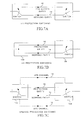
- NEs 12 may be configured to provide 1:1 or 1+1 VC protection switching as illustrated in FIGS. 7A and 7B , respectively.
- FIGS. 7A and 7B only illustrate protection switching in a single direction for traffic carried from NE 12a to NE 12b .
- Entity 14 acts as a working entity
- entity 16 acts as a protection entity for entity 14 .
- traffic is transported on entity 14 .
- entity 16 is provisioned but does not carry redundant traffic ( FIG. 7A ).
- For 1+1 protection switching entities 14 and 16 carry identical traffic ( FIG. 7B ). States representative of the entities 14 and 16 are maintained at NE 12a and 12b .
- NE 12a upon detection of a conventional defect, such as an LOC, LOD, LOS, NE 12a generates AIS cells ( FIGS. 2 and 3 ); notes an AIS state for entity 14 ; and passes the AIS cells to NE 12b on the VPI/VCI channel over entity 14 .
- NE 12b in turn, generates RDI cells, and passes them along the upstream channel of entity 14 to NE 12a .
- NE 12a For 1:1 protection switching and assuming that the state of entity 16 , as maintained by NE 12a , does not indicate a failure, NE 12a also switches traffic previously carried on entity 14 to entity 16 , as schematically illustrated in FIG. 7A .
- NE 12b Upon receipt of traffic on entity 16 , NE 12b utilizes this traffic in place of traffic on entity 14 .
- traffic need not be switched between entity 14 and 16 at NE 12a .
- the signal degrade detector 66 ( FIG. 6 ) of NE 12a monitors SONET overhead bytes B3 or V5 and determines a BER at the path level of the SONET layer. Upon noting a BER higher than a preset maximum, provisioned at monitor 66 , the signal degrade detector 66 generates a trigger that is provided to ATM processor 48 ( FIG.5 ). In the example embodiment, a BER threshold of 10 -3 bits/second is preferably chosen. ATM processor 48 , in turn generates ATM OAM cells indicative of signal degrade.
- NE 12a Preferably, NE 12a generates OAM CP cells as illustrated in FIGS. 2 and 4 .
- fields 40 and 42 of each CP cell contains a status indicator indicating the signal degrade received from the SONET layer.
- the first four bits of field 40 are set to a value of 1000 (binary) indicating signal degrade of the working entity.
- NE 12a For 1:1 protection switching and assuming that the state of entity 16 is not failed, NE 12a begins to transmit data carried on entity 14 on the protection entity carried by entity 16 .
- NE 12b upon receipt of the CP cell, uses traffic received on entity 16 in favour of traffic on entity 14 .
- NE 12a continues to monitor the signal degrade at the SONET layer of entity 14 and periodically generates and insert CP cells indicative of this signal degrade state of entity 14 .
- NE 12a similarly monitors the signal degrade state of entity 16 .
- similar CP cells with the first four bits of field 40 populated with the value 1001, indicating signal degrade of the protection entity are inserted into the channel carried by entity 16 .
- NEs 12a and 12b continue to transport data on entity 16 in favour of entity 14 until the state of entity 14 changes to indicate no further signal degrade, or until the state of entity 16 indicates a more severe condition on entity 16 than entity 14 . That is, in the event that entity 16 assumes a signal fail state, traffic may be switched back to entity 14 , even in the event of a signal degrade condition on entity 14 .
- NE 12b may switch to protection entity immediately upon detecting signal degrade on working entity 14 .
- NEs 12 a and 12b may be configured to provide protection switching in VPGs or VCGs and thus provide protection switching, as illustrated in FIG. 7C.
- FIG. 7C only illustrates protection switching for traffic transported from NE 12a to NE 12b .
- An APS channel on link 18 carries OAM cells relevant to group protection switching for the group that includes entity 14 .
- entity 14 acts as a working entity
- entity 16 acts as a protection entity and is thus part of the protection group.
- traffic is transported on entity 14 .
- Entity 16 is provisioned but does not carry redundant traffic.
- NE 12a Upon detection of a conventional fault, such as an LOC, LOD, LOS, NE 12a generates AIS cells and passes them to NE 12b on the APS channel on link 18 and on any channel within the VPG on entity 14 .
- NE 12b in turn generates RDI cells, and passes them along the APS channel and any affected channel to NE 12a .
- NE 12b also switches traffic previously carried on entity 14 to entity 16 , as illustrated. Upon receipt of traffic on entity 16 , NE 12b switches to receive this traffic in place of traffic on entity 14 .
- signal degrade detector 66 of NE 12a monitors SONET overhead parity bytes B3 of V5 and determines a BER at the path level of the SONET layer. Upon noting a BER higher than a preset maximum, degrade monitor 66 generates a trigger that is provided to ATM processor 48. In the example embodiment, a BER threshold of 10 -3 bits/second is preferably chosen. Again, ATM processor 48 , in turn, injects ATM OAM cells indicative of signal degrade. Preferably, NE 12a generates OAM AIS cells as illustrated in FIGS. 2 and 3 on the APS channel carried on link 18 associated with the working entity 14 .
- fields 34 of each AIS cell contains a newly defined value, SDType, indicating the signal degrade received from the SONET layer.
- SDType indicating the signal degrade received from the SONET layer.
- Such AIS cell may thus be referred to as an AIS-SD cell.
- Field 36 may optionally identify the NE generating the OAM AIS-SD cell. Assuming that the state of entity 16 is not failed, NE 12a begins to transmit data carried on entity 14 on the protection entity carried by entity 16 . NE 12b , upon receipt of the AIS-SD cell, uses traffic transported on entity 16 in favour of traffic on entity 14 .
- NE 12a continues to monitor the signal degrade state of entity 14 and periodically, preferably at one second intervals, generates and injects AIS-SD cells indicative of this signal degrade state of entity 14 on the APS channel on link 18 .
- NE 12a similarly monitors the signal degrade state of entity 16 .
- AIS cells are generated on link 19 .
- NEs 12a and 12b continue to transport traffic on entity 16 in favour of entity 14 until no AIS-SD cells are received for a defined duration (of preferably between about 2.0 and 3.0 seconds) or until another AIS cell indicates a more severe condition of entity 16 than entity 14 .
- AIS-SD cells are preferably only carried on the established APS channel 18 . In this way, the generation of AIS-SD cells does not impair the transport of traffic on entity 14 .
- protection switching for VP and VPGs will function similarly.
- CP cells could alternatively be passed on an APS channel to effect protection switching.
- CP cells and AIS cells is somewhat arbitrary, and may be varied, as understood by one of ordinary skill in the art.
Landscapes
- Engineering & Computer Science (AREA)
- Computer Networks & Wireless Communication (AREA)
- Data Exchanges In Wide-Area Networks (AREA)
Abstract
Description
Claims (21)
- A method of switching traffic transported on a working entity of an ATM network to a protection entity on said ATM network, the ATM traffic carried on a physical network adhering to a physical layer protocol, the method comprising:monitoring an indicator of signal degrade of said working entity provided by said physical layer protocol; andin response to detecting a degraded signal as a result of said monitoring, generating ATM cells indicative of said signal degrade on said ATM network.
- The method of claim 1, further comprising:
in response to said ATM cells indicative of said signal degrade, receiving said traffic on said protection entity. - The method of claim 1 or 2, further comprising:
in response to said ATM cells indicative of said signal degrade, transmitting said traffic on said protection entity from a source network element. - The method of claim 1, 2, or 3, wherein said monitoring comprises calculating a bit-error-rate from SONET path overhead.
- The method of claim 4, wherein said calculating utilizes a parity check field within said SONET path overhead to determine said bit error rate.
- The method of claim 4 or 5, wherein said ATM cells indicative of signal degrade are generated in response to said bit-error-rate exceeding a defined threshold.
- The method of claim 6, wherein said ATM cells comprise ATM alarm indication signal ("AIS") cells.
- The method of claim 7, wherein said AIS cells are transmitted from a network element detecting said signal degrade to a downstream network element using an ATM signaling channel.
- The method of claim 8, wherein said ATM signaling channel comprises an ATM protection switching channel.
- The method of claim 6, wherein said ATM cells comprise an ATM protection switching coordination protocol ("CP") cell.
- The method of claim 10, wherein said CP cell is transmitted within one of said working entity and said protection entity.
- A network element for use in an ATM network in which ATM traffic is carried on a physical network adhering to a physical layer protocol, said network element operable to cause traffic transported on a working entity of said ATM network to be transported on a protection entity on said ATM network, said network element comprising:
a detector for monitoring an indicator of signal degrade of said working entity provided by said physical layer protocol. - The network element of claim 12, wherein said detector generates a trigger indicative of signal degrade in response to monitoring signal degrade of said working entity.
- The network element of claim 12 or 13, further comprising an ATM switch, in communication with an ATM processor, wherein said detector is in communication with said ATM processor, and wherein said ATM processor generates ATM cells indicative of signal degrade in response to said trigger.
- The network element of claim 12, 13 or 14, wherein said ATM cells comprise ATM alarm indication signal ("AIS") cells.
- The network element of claim 13, wherein said ATM cells comprise an ATM protection switching coordination protocol ("CP") cell.
- The network element of claim 15, wherein said AIS cells are transmitted to a downstream network element using an ATM signaling channel.
- A network element for use in an ATM network in which ATM traffic is carried on a physical network adhering to a physical layer protocol, said network element operable to switch traffic transported on a working entity of said ATM network to a protection entity on said ATM network, said network element comprising:means for monitoring an indicator of signal degrade at said physical layer of said working entity provided by said physical layer protocol;means for generating ATM cells indicative of signal degrade in response to said means for monitoring signal degrade at said physical layer.
- Computer memory storing program instructions, adapting an ATM network element on ATM network in which ATM traffic is carried on a physical network adhering to a physical layer protocol, to;a) monitor an indicator of signal degrade of a working entity on said ATM network provided by said physical layer protocol;b) in response to detecting a degraded signal as a result of said monitoring, generate ATM cells indicative of said signal degrade on said ATM network.
- An ATM cell comprising an alarm indication signal ("AIS"), embodied in a carrier wave to be transported on an ATM network, said cell comprising:a field identifying said cell as an ATM AIS cell; anda field including an indicator of signal degrade on said network.
- A computer program element comprising computer program code means arranged to make a controller execute procedure to perform the method of any of claims 1 to 11.
Applications Claiming Priority (2)
| Application Number | Priority Date | Filing Date | Title |
|---|---|---|---|
| US392454 | 1995-02-22 | ||
| US09/392,454 US6898177B1 (en) | 1999-09-09 | 1999-09-09 | ATM protection switching method and apparatus |
Publications (2)
| Publication Number | Publication Date |
|---|---|
| EP1083711A2 true EP1083711A2 (en) | 2001-03-14 |
| EP1083711A3 EP1083711A3 (en) | 2003-04-16 |
Family
ID=23550669
Family Applications (1)
| Application Number | Title | Priority Date | Filing Date |
|---|---|---|---|
| EP00307794A Withdrawn EP1083711A3 (en) | 1999-09-09 | 2000-09-08 | ATM protection switching method and apparatus |
Country Status (2)
| Country | Link |
|---|---|
| US (1) | US6898177B1 (en) |
| EP (1) | EP1083711A3 (en) |
Cited By (6)
| Publication number | Priority date | Publication date | Assignee | Title |
|---|---|---|---|---|
| WO2002054641A1 (en) * | 2000-12-29 | 2002-07-11 | Telefonaktiebolaget Lm Ericsson | Controlled handling of far end at equipment failure in an msp+1 unidirectionnal configuration |
| US6915463B2 (en) | 2001-12-26 | 2005-07-05 | Richard Charles Vieregge | System and method for performing pre-emptive protection switching |
| US20110038258A1 (en) * | 2008-04-22 | 2011-02-17 | Jia He | Method and system for service protection |
| WO2012088802A1 (en) * | 2010-12-29 | 2012-07-05 | 中兴通讯股份有限公司 | Method and system for detecting signal degrade (sd) alarm |
| EP2506501A4 (en) * | 2009-11-24 | 2016-05-11 | Zte Corp | METHOD AND SYSTEM FOR IMPLEMENTING RING NETWORK PROTECTION |
| CN112468394A (en) * | 2019-09-09 | 2021-03-09 | 中国移动通信有限公司研究院 | Protection switching method, node equipment and storage medium |
Families Citing this family (6)
| Publication number | Priority date | Publication date | Assignee | Title |
|---|---|---|---|---|
| EP1334587A1 (en) * | 2000-08-31 | 2003-08-13 | Padcom Inc. | Method and apparatus for routing data over multiple wireless networks |
| US7079551B2 (en) * | 2000-10-05 | 2006-07-18 | Kiribati Wireless Ventures, Llc | Private network link verification procedure in free space optical communication network |
| US6917759B2 (en) * | 2002-01-31 | 2005-07-12 | Nortel Networks Limited | Shared mesh signaling algorithm and apparatus |
| US7197008B1 (en) * | 2002-07-05 | 2007-03-27 | Atrica Israel Ltd. | End-to-end notification of local protection using OAM protocol |
| JP4798074B2 (en) * | 2007-06-26 | 2011-10-19 | 日本電気株式会社 | Interface switching method and apparatus |
| CN112751696B (en) * | 2019-10-31 | 2022-08-05 | 烽火通信科技股份有限公司 | Method and system for transmitting in-band SD signal in communication network |
Family Cites Families (12)
| Publication number | Priority date | Publication date | Assignee | Title |
|---|---|---|---|---|
| US5793745A (en) | 1996-05-06 | 1998-08-11 | Bell Communications Research, Inc. | Bundled protection switching in a wide area network background of the invention |
| US5764651A (en) * | 1996-05-17 | 1998-06-09 | Integrated Device Technology, Inc. | Bit error rate detection system |
| US6256292B1 (en) * | 1996-07-11 | 2001-07-03 | Nortel Networks Corporation | Self-healing line switched ring for ATM traffic |
| US5838924A (en) | 1996-08-06 | 1998-11-17 | Lucent Technologies Inc | Asynchronous transfer mode (ATM) connection protection switching apparatus and method |
| JP3011130B2 (en) * | 1996-10-11 | 2000-02-21 | 日本電気株式会社 | ATM signal switching device |
| JP3302578B2 (en) * | 1996-10-21 | 2002-07-15 | 富士通株式会社 | OAM processing equipment |
| JPH10173657A (en) * | 1996-12-13 | 1998-06-26 | Fujitsu Ltd | Transmission equipment |
| JPH10336195A (en) * | 1997-06-02 | 1998-12-18 | Nec Corp | Selective VP end switching method |
| US6452906B1 (en) * | 1997-08-20 | 2002-09-17 | At&T Corp. | Fault detection and isolation in a synchronous optical network (SONET) and in a synchronous digital hierarchy (SDH) network |
| EP1010346B1 (en) * | 1997-08-22 | 2003-10-15 | Nortel Networks Limited | Protection switching trigger generation |
| JP3811007B2 (en) | 1998-02-20 | 2006-08-16 | エーディーシー テレコミュニケーションズ,インコーポレイティド | Virtual connection protection switching |
| US6353593B1 (en) * | 1999-06-03 | 2002-03-05 | Fujitsu Network Communications, Inc. | Protection architecture for virtual channel connections (VCCS) in a telecommunications network |
-
1999
- 1999-09-09 US US09/392,454 patent/US6898177B1/en not_active Expired - Lifetime
-
2000
- 2000-09-08 EP EP00307794A patent/EP1083711A3/en not_active Withdrawn
Cited By (8)
| Publication number | Priority date | Publication date | Assignee | Title |
|---|---|---|---|---|
| WO2002054641A1 (en) * | 2000-12-29 | 2002-07-11 | Telefonaktiebolaget Lm Ericsson | Controlled handling of far end at equipment failure in an msp+1 unidirectionnal configuration |
| US6915463B2 (en) | 2001-12-26 | 2005-07-05 | Richard Charles Vieregge | System and method for performing pre-emptive protection switching |
| US20110038258A1 (en) * | 2008-04-22 | 2011-02-17 | Jia He | Method and system for service protection |
| EP2276200A4 (en) * | 2008-04-22 | 2011-08-10 | Huawei Tech Co Ltd | METHOD AND SYSTEM FOR SERVICE PROTECTION |
| US8670306B2 (en) * | 2008-04-22 | 2014-03-11 | Huawei Technologies Co., Ltd. | Method and system for service protection |
| EP2506501A4 (en) * | 2009-11-24 | 2016-05-11 | Zte Corp | METHOD AND SYSTEM FOR IMPLEMENTING RING NETWORK PROTECTION |
| WO2012088802A1 (en) * | 2010-12-29 | 2012-07-05 | 中兴通讯股份有限公司 | Method and system for detecting signal degrade (sd) alarm |
| CN112468394A (en) * | 2019-09-09 | 2021-03-09 | 中国移动通信有限公司研究院 | Protection switching method, node equipment and storage medium |
Also Published As
| Publication number | Publication date |
|---|---|
| EP1083711A3 (en) | 2003-04-16 |
| US6898177B1 (en) | 2005-05-24 |
Similar Documents
| Publication | Publication Date | Title |
|---|---|---|
| US6654923B1 (en) | ATM group protection switching method and apparatus | |
| US6301254B1 (en) | Virtual path ring protection method and apparatus | |
| CA2207538C (en) | Asynchronous transfer mode (atm) connection protection switching apparatus and method | |
| EP0986226B1 (en) | Ip packet communication apparatus | |
| US6952395B1 (en) | Optical network restoration | |
| KR100540408B1 (en) | Truncated Connection Detection Method and Apparatus Using Next Hop Loopback | |
| EP0983709B1 (en) | Operations and maintenance data flows over a point-to-multipoint broadband access network | |
| CA2252807C (en) | Bundled protection switching in a wide area network | |
| US5636206A (en) | System for achieving alarm masking processing | |
| CA2391672C (en) | Transport network with circuitry for monitoring packet path accommodated in stm path | |
| US6898177B1 (en) | ATM protection switching method and apparatus | |
| EP0964543B1 (en) | Telecommunications system with tandem connection monitoring | |
| CN101471837B (en) | Optical channel data cell sharing protection ring, signal transmission method and network node | |
| US20040221058A1 (en) | Nested protection switching in a mesh connected communications network | |
| JP3011130B2 (en) | ATM signal switching device | |
| US7269129B2 (en) | Transmitting apparatus | |
| JP4207297B2 (en) | Packet communication device | |
| US20030142678A1 (en) | Virtual path ring protection method and apparatus | |
| US7706268B2 (en) | Transmission device | |
| AU752607B2 (en) | High speed transfer of failure information in an ATM network | |
| SECTOR et al. | ITU-Tg. 808.1 | |
| Randhawa et al. | Performance Management in Broadband Networks |
Legal Events
| Date | Code | Title | Description |
|---|---|---|---|
| PUAI | Public reference made under article 153(3) epc to a published international application that has entered the european phase |
Free format text: ORIGINAL CODE: 0009012 |
|
| AK | Designated contracting states |
Kind code of ref document: A2 Designated state(s): AT BE CH CY DE DK ES FI FR GB GR IE IT LI LU MC NL PT SE |
|
| AX | Request for extension of the european patent |
Free format text: AL;LT;LV;MK;RO;SI |
|
| PUAL | Search report despatched |
Free format text: ORIGINAL CODE: 0009013 |
|
| AK | Designated contracting states |
Designated state(s): AT BE CH CY DE DK ES FI FR GB GR IE IT LI LU MC NL PT SE |
|
| AX | Request for extension of the european patent |
Extension state: AL LT LV MK RO SI |
|
| RIC1 | Information provided on ipc code assigned before grant |
Ipc: 7H 04Q 11/04 B Ipc: 7H 04L 12/56 A |
|
| RAP1 | Party data changed (applicant data changed or rights of an application transferred) |
Owner name: NORTEL NETWORKS LIMITED |
|
| 17P | Request for examination filed |
Effective date: 20030916 |
|
| 17Q | First examination report despatched |
Effective date: 20031015 |
|
| AKX | Designation fees paid |
Designated state(s): DE FR GB |
|
| STAA | Information on the status of an ep patent application or granted ep patent |
Free format text: STATUS: THE APPLICATION IS DEEMED TO BE WITHDRAWN |
|
| 18D | Application deemed to be withdrawn |
Effective date: 20050118 |