EP1083681A1 - Repeater - Google Patents
Repeater Download PDFInfo
- Publication number
- EP1083681A1 EP1083681A1 EP00911421A EP00911421A EP1083681A1 EP 1083681 A1 EP1083681 A1 EP 1083681A1 EP 00911421 A EP00911421 A EP 00911421A EP 00911421 A EP00911421 A EP 00911421A EP 1083681 A1 EP1083681 A1 EP 1083681A1
- Authority
- EP
- European Patent Office
- Prior art keywords
- signals
- base station
- array antenna
- adaptive array
- dimensional
- Prior art date
- Legal status (The legal status is an assumption and is not a legal conclusion. Google has not performed a legal analysis and makes no representation as to the accuracy of the status listed.)
- Withdrawn
Links
Images






Classifications
-
- H—ELECTRICITY
- H04—ELECTRIC COMMUNICATION TECHNIQUE
- H04B—TRANSMISSION
- H04B7/00—Radio transmission systems, i.e. using radiation field
- H04B7/14—Relay systems
- H04B7/15—Active relay systems
-
- H—ELECTRICITY
- H04—ELECTRIC COMMUNICATION TECHNIQUE
- H04B—TRANSMISSION
- H04B7/00—Radio transmission systems, i.e. using radiation field
- H04B7/14—Relay systems
- H04B7/15—Active relay systems
- H04B7/155—Ground-based stations
- H04B7/15528—Control of operation parameters of a relay station to exploit the physical medium
- H04B7/1555—Selecting relay station antenna mode, e.g. selecting omnidirectional -, directional beams, selecting polarizations
-
- H—ELECTRICITY
- H01—ELECTRIC ELEMENTS
- H01Q—ANTENNAS, i.e. RADIO AERIALS
- H01Q1/00—Details of, or arrangements associated with, antennas
- H01Q1/12—Supports; Mounting means
- H01Q1/22—Supports; Mounting means by structural association with other equipment or articles
- H01Q1/24—Supports; Mounting means by structural association with other equipment or articles with receiving set
- H01Q1/241—Supports; Mounting means by structural association with other equipment or articles with receiving set used in mobile communications, e.g. GSM
- H01Q1/242—Supports; Mounting means by structural association with other equipment or articles with receiving set used in mobile communications, e.g. GSM specially adapted for hand-held use
-
- H—ELECTRICITY
- H01—ELECTRIC ELEMENTS
- H01Q—ANTENNAS, i.e. RADIO AERIALS
- H01Q25/00—Antennas or antenna systems providing at least two radiating patterns
-
- H—ELECTRICITY
- H01—ELECTRIC ELEMENTS
- H01Q—ANTENNAS, i.e. RADIO AERIALS
- H01Q3/00—Arrangements for changing or varying the orientation or the shape of the directional pattern of the waves radiated from an antenna or antenna system
- H01Q3/26—Arrangements for changing or varying the orientation or the shape of the directional pattern of the waves radiated from an antenna or antenna system varying the relative phase or relative amplitude of energisation between two or more active radiating elements; varying the distribution of energy across a radiating aperture
-
- H—ELECTRICITY
- H04—ELECTRIC COMMUNICATION TECHNIQUE
- H04B—TRANSMISSION
- H04B7/00—Radio transmission systems, i.e. using radiation field
- H04B7/14—Relay systems
- H04B7/15—Active relay systems
- H04B7/155—Ground-based stations
- H04B7/15528—Control of operation parameters of a relay station to exploit the physical medium
- H04B7/15542—Selecting at relay station its transmit and receive resources
-
- H—ELECTRICITY
- H04—ELECTRIC COMMUNICATION TECHNIQUE
- H04W—WIRELESS COMMUNICATION NETWORKS
- H04W16/00—Network planning, e.g. coverage or traffic planning tools; Network deployment, e.g. resource partitioning or cells structures
- H04W16/24—Cell structures
- H04W16/26—Cell enhancers or enhancement, e.g. for tunnels, building shadow
-
- Y—GENERAL TAGGING OF NEW TECHNOLOGICAL DEVELOPMENTS; GENERAL TAGGING OF CROSS-SECTIONAL TECHNOLOGIES SPANNING OVER SEVERAL SECTIONS OF THE IPC; TECHNICAL SUBJECTS COVERED BY FORMER USPC CROSS-REFERENCE ART COLLECTIONS [XRACs] AND DIGESTS
- Y02—TECHNOLOGIES OR APPLICATIONS FOR MITIGATION OR ADAPTATION AGAINST CLIMATE CHANGE
- Y02D—CLIMATE CHANGE MITIGATION TECHNOLOGIES IN INFORMATION AND COMMUNICATION TECHNOLOGIES [ICT], I.E. INFORMATION AND COMMUNICATION TECHNOLOGIES AIMING AT THE REDUCTION OF THEIR OWN ENERGY USE
- Y02D30/00—Reducing energy consumption in communication networks
- Y02D30/70—Reducing energy consumption in communication networks in wireless communication networks
Definitions
- the present invention relates to a digital mobile communication system such as a cellular system and so forth.
- a radio area when a radio area is intended to be enlarged, for instance, in a cellular system, when a radius of a cell is intended to be enlarged, the mobile communication system causes a transmission signal to be propagated in the distance while employing an amplifier with large amplification factor, since when a high-frequency wave is employed, a propagation loss is remarkable.
- enlargement of a radio area is performed in such a way that a mobile communication system places many base stations.
- An object of the present invention is to provide a repeater apparatus capable of enlarging an radio area of a base station while suppressing an increase of the size of a base station, power consumption of a mobile station, the costs of the whole system, and interference in an adjacent cell.
- This object is achieved in such a way that a repeater which is provided with a filter causing a specified channel to be passed is placed within a cell of a base station, and which passes specified frequencies used in the base station through the repeater and propagates them outer side of the cell in the distance. For this reason, it is possible to enlarge a cell area for only specified channel (specific frequency).
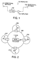
- FIG. 1 is a block diagram illustrating a configuration of a repeater applied to a mobile communication system according to an embodiment 1 of the present invention.
- a repeater 100 illustrated in FIG. 1 is configured to be provided with a directional antenna 101 for receiving a radio wave of a specific direction, a filter for filtering (extracting) predetermined signal from among signals received by the directional antenna 101, an amplifier 103 for amplifying signals passed through the filter 102, and a directional antenna 104 for transmitting the signal amplified by the amplifier 103 in a specific direction.
- a filter 102 when the repeater 100 is applied to FDMA (Frequency Division Multiple Access) system, a FDMA filter which passes through signals of only specific frequency is used.
- FDMA Frequency Division Multiple Access
- CDMA Code Division Multiple Access
- CDMA Code Division Multiple Access
- TDMA Time Division Multiple Access
- a TDMA filter which passes through signals during only specific time is used. In other words, the filter 100 passes through only signals of predetermined channel.
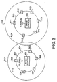
- the repeaters 201 to 204 are placed along circumference of the cell 206 formed by a radio wave of the base station 205.
- the repeaters 201 to 204 are set so as to pass only a frequency f1.
- Directional antennas of reception sides of the repeaters 201 to 204 are set in a direction of the base station 205.
- the repeaters 201 to 204 pass and amplify only a signal of the frequency f1. Consequently, since the signal of the frequency f1 reaches in the distance, radio wave areas 207 to 210 are formed in the outer side of the cell 206.
- the repeaters 201 to 204 are placed along circumference of the cell 206 with an interval of 90 degrees.
- the radio wave areas 207 to 210 are formed independently due to the repeaters 201 to 204.
- it is also suitable that a radio wave area is formed in the outer side of the cell 206 over the whole circumference thereof while using more repeaters.
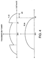
- a plurality of repeaters 303 to 308 for passing frequencies f1 and f2 are formed along circumference of a cell 302 formed by a radio wave of a base station 301. While a plurality of repeaters 311 to 316 for passing frequencies f3 and f4 are formed along circumference of a cell 310 formed by a radio wave of a base station 309. Further, respective cells 302 and 310 are formed so that two cells do not cross with each other.
- the repeaters 311 to 316 pass and amplify signals of the frequencies f3 and f4, the signals of the frequencies f3 and f4 reach in the distance, thus a radio wave area 318 of the frequencies f3 and f4 is formed in the outer side of the cell 310.
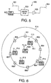
- the transmitting power (transmission signal power) of signals corresponding to the frequencies f1 to f4 among signals transmitted by the base station 301 is maintained at a value by which a mobile station can perform communication appropriately to a position d1 where the repeaters 303 to 308 are placed. Subsequently, with reference to the transmitting power of signals corresponding to the frequencies f3 and f4 among signals transmitted by the base station 301, the transmitting power is attenuated to a value by which the mobile station becomes impossible to perform communication appropriately in an attenuation position d2.
- the transmitting power is attenuated to a value by which the mobile station becomes impossible to perform communication appropriately in an attenuation position d3 not the attenuation position d2.
- one side passes through only the frequencies f1 and f2 with the repeaters 303 to 308, while the other side passes through the frequencies f3 and f4 with the repeaters 311 to 316.
- Both base stations use the frequencies f1 to f4 in small areas 302 and 310. While in large areas 317 and 318 crossing each other, one base station can use the frequencies f1 and f2, and the other base station can use the frequencies f3 and f4 without interfering each other. Thus it is possible to improve frequency utilization efficiency.
- the present embodiment is not required to use the amplifier with large amplification factor in a base station different from a conventional way, consequently, the size of the base station does not become large.
- a mobile station such as a portable telephone and so forth can perform communication while utilizing a radio area formed by repeaters with an original configuration, power consumption does not become large different from the conventional way.
- any base station can use 124 waves, further, 31 waves each become possible to be used according to only the cell formed due to the repeaters. For that reason, frequency utilization efficiency is improved remarkably.
- FIG. 5 is a block diagram illustrating a configuration of an adaptive repeater applied to a mobile communication system according to an embodiment 2 of the present invention.
- An adaptive repeater 500 illustrated in FIG. 5 is configured to be provided with a directional antenna 501 for receiving a radio wave in a specific direction, an adaptive filter 502 for filtering predetermined signal adaptively among signals received by the directional antenna 501, an amplifier 503 for amplifying signals passed through the adaptive filter 502, and a directional antenna 504 for transmitting signals amplified by the amplifier 503 in a specific direction.
- Adaptive control of signal filtering of the adaptive filter 502 is one in which a parameter passing signals is possible to be changed arbitrarily. This control is performed through cable communications or radio communications from a base station 505.
- the adaptive filter 502 is the FDMA filter
- control is performed for changing frequencies to be passed, for instance, for changing the frequency f1 into the frequency f2 in every predetermined time.
- the adaptive filter 502 is the CDMA filter
- control is performed for changing specified codes to be passed, for instance, for changing the specified code c1 into the specified code c2 in every predetermined time.
- the adaptive filter 502 is the TDMA filter
- control is performed for changing signal passing time as well as signal passing time period and so forth.
- signals to be passed are capable of being changed in accordance with positions of respective mobile stations within a cell.
- adaptive repeaters 601 to 608 are placed along circumference of a cell 610 formed by a radio wave of a base station 609.
- a base station 505 controls adaptive filters of the adaptive repeaters 601 to 608 so as to pass, for instance, only a frequency f1.
- a radio wave area 615 in accordance with the frequency f1 is formed on the outside of the cell 610. Then, the mobile station 614 becomes possible to perform communication appropriately while using this frequency f1.
- the base station 609 controls the adaptive filters of the adaptive repeaters 601 to 608 so as to pass only the frequencies f1, f2 and f3 which a plurality of the mobile stations 612 to 614 use.
- a radio wave area 701 in accordance with the frequencies f1 to f3 is formed on the outside of the cell 610, thus the mobile stations 612 to 614 become possible to perform communication appropriately while employing the frequencies f1 to f3.
- the base station detects distance to the mobile station in such a way that the base station measures time required for back and forth between the mobile station and the perch channel. In another way, the base station detects distance of the mobile station therebetween in such a way that the base station measures reception power in reverse direction from the mobile station to the base station.
- adaptive repeaters 801 to 803 are placed with a long distance, for instance, the adaptive repeaters 801 to 803 are placed with interval of 120 degrees along a cell 805 of a base station 804. If the base station 804 controls so as to pass different frequencies f1, f2 or f3 in every each adaptive repeater f1, f2 or f3, it is possible to be performed communication while forming dedicated radio wave areas 809 to 811 on the outside of the cell 805 of the base station 804 for the sake of respective mobile stations 806 to 808 existing separately therefrom mutually.
- the present embodiment since the adaptive filters are used for the adaptive repeaters, when a mobile station exists on the outside of the cell (in the distance) formed in accordance with the base station, the present embodiment is possible to control operation such that only signals of frequency which the mobile station uses are amplified while passing through the adaptive filter of the adaptive repeater.
- the present embodiment is not required to use the amplifier with large amplification factor in a base station different from a conventional way, consequently, the size of the base station does not become large. Since a mobile station such as a portable telephone and so forth can perform communication while utilizing a radio area formed in accordance with adaptive repeaters with an original configuration as it is, power consumption does not become large contrary to the conventional way.
- FIG. 9 is a block diagram illustrating a configuration of an inverting repeater applied to a mobile communication system according to an embodiment 3 of the present invention.
- An inverting repeater 900 illustrated in FIG. 9 is configured to be used an inverting amplifier 903 instead of the amplifier 103 of the repeater 100 illustrated in FIG. 1.
- a frequency signal passed through a filter 102 is not only amplified by the inverting amplifier 903, but also inverted so as to come to opposite phase. For this reason, an input frequency is eliminated while denying mutually caused by addition of input/output frequency. Namely, signals received by an antenna 101 deny signals transmitted from an antenna 104 mutually. As a result, it is possible not to reach the input frequency beyond the inverting repeater 900.
- an inverting repeater 1005 is placed in a crossing area of the cells 1003 and 1004.
- the mobile station 1006 when a mobile station 1006 performs a hand-over with movement from one side of the base station 1001 to the other side base station 1002 while existing in this crossing portion, the mobile station 1006 should judge whether which of a reception signal from the base station 1001 in reception at present and a reception signal from the adjacent base station 1002.
- the mobile station 1006 when the inverting repeater 1005 sets to stop a traffic channel from the base station 1002 in order to pass only a perch channel (control channel), the mobile station 1006 is capable of performing above-described judgement from the perch channel. Further, in this case, since a traffic channel whose interference is not desired is stopped by the inverting repeater 1005, the mobile station 1006 is capable of performing the hand-over while performing appropriate talking with only the traffic channel of one frequency used.
- the inverting amplifier 903 inverts only signals passed adaptively. According to this processing, it is possible to eliminate the passed frequency of signals. For instance, in FIG. 12, a plurality of inverting repeaters 1203 to 1208 are placed along a cell 1202 formed due to a base station 1201. If frequencies f3 and f4 among frequencies f1 to f4 employed in the base station 1201 are stopped by the inverting repeaters 1203 to 1208, a cell 1209 in accordance with the frequencies f1 and f2 of the signals can be formed on the outside of the cell 1202.
- Transmitting power (transmission signal power) of signals corresponding to frequencies f3 and f4 among signals transmitted by the base station 1201 reaches to a position d1 where the inverting repeaters 1201 to 1208 are placed.
- the transmitting power is attenuated to a value that is one in which a mobile station is impossible to perform communication appropriately.
- transmitting power of signals corresponding to frequencies f1 and f2 among signals transmitted by the base station 1201 is attenuated to a value that is one in which a mobile station is impossible to perform communication appropriately in an ordinary attenuation position d2.
- a plurality of base stations 1403 to 1405 which use the same frequency f1 as a base station 1401 are placed on the inside of a primary cell 1402 formed due to the base station 1401. If inverting repeaters 1406 to 1408 with an inverting amplifier 903 are placed in between the base stations 1403 to 1405 and the base station 1401, the frequency f1 of the primary cell 1402 is stopped at the inverting repeaters 1406 to 1408.
- a plurality of the base stations 1403 to 1405 capable of forming micro cells 1409 to 1411 with the same frequency f1 respectively on the inside of the primary cell 1402.
- a mobile station can perform communication employing different signals with the same frequency f1 because the mobile station capable of performing communication employing the same frequency f1 to different base stations 1401, 1403 to 1405.
- the frequency of the signal passed through the filter of the inverting repeater or the adaptive filter is inverted by the inverting amplifier 903 so that the passed frequency is denied in the output side, therefore, it is possible to eliminate an input frequency of signals passed through a filter. Namely, it is possible not to reach a specific input frequency beyond the inverting repeater.
- the present embodiment is not required to employ the amplifier with large amplification factor in a base station different from a conventional way, consequently, the size of the base station does not become large. Since a mobile station such as a portable telephone and so forth can perform communication while utilizing a radio area formed in accordance with inverting repeaters with an original configuration as it is, thus power consumption does not become large contrary to the conventional way.
- FIG. 15 is a block diagram illustrating a configuration of a three-dimensional channel selection adaptive array antenna applied to a base station of a mobile communication system according to an embodiment 4 of the present invention.
- a three-dimensional channel selection adaptive array antenna 1500 (hereinafter referred to as only antenna) illustrated in FIG. 15 is configured to be provided with filters 1501 and 1502, modulators 1503 and 1504, first phase shifters 1505 to 1508, second phase shifters 1509 to 1512, adders 1513 to 1516, antenna elements 1517 to 1520, a demodulator 1521, and a three-dimensional directivity phase controller 1522.
- the antenna elements 1517 to 1520 have a three-dimensional antenna structure. Specifically, this antenna element prepares the predetermined numbers of planes with a position relationship of approximately even with the ground.
- the antenna elements 1517 to 1520 are configured while placing a plurality of antenna arrays on the respective planes.
- respective planes are located in the direction of approximately vertical with the ground mutually with predetermined interval.
- there is no limitation of arrangement method of a plurality of antenna arrays on respective planes it is appropriate to place a plurality of antenna arrays regularly in respective antennas in view of easy operation. For instance, in the respective planes, a plurality of antenna arrays are placed in a line with predetermined intervals. While, a plurality of antenna arrays are placed so as to form a cross.
- the filter 1501 the first to the N-th transmission data (f1 and f2) among the first to the M-th transmission data are passed through the filter 1501 to be outputted to the modulator 1503.
- the first to the M-th transmission data (f1, f2, f3 and f4) are passed through the filter 1502 to be outputted to the modulator 1504.
- the first to the N-th transmission data (f1 and f2) are modulated depending on a predetermined frequency of carrier (f1 or f2), before being outputted to the first phase shifters 1505 to 1508.
- the first to the M-th transmission data (f1, f2, f3 and f4) are modulated depending on a predetermined frequency of carrier (any of f1 to f4), before being outputted to the second phase shifters 1509 to 1512.
- the signals passed through the first phase shifters 1505 to 1508 as well as passed through the second phase shifters 1509 to 1512 are added in the adders 1513 to 1516 to be transmitted through the antenna elements 1517 to 1521.
- signals received by the antenna elements 1517 to 1520 are demodulated by the demodulator 1521.
- the demodulated first to M-th reception data (f1, f2, f3 and f4) are outputted to the three dimensional directivity phase controller 1522.
- the three-dimensional directivity phase controller 1522 performs control for adding predetermined directivity to signals from the modulators 1503 and 1504 in the first phase shifters 1505 to 1508 as well as the second phase shifters 1509 and 1512 in accordance with the first to the M-th reception data (f1, f2, f3 and f4).
- this control is to possess directivity with arbitrary angles ⁇ 1 and ⁇ 2 in vertical direction from an antenna 1500 in high position, which the antenna 1500 is mounted on a base station 1601.
- this configuration as illustrated in FIG. 17, it is possible to form inherent doughnut-shaped radio wave areas (cells) 1602 and 1603 in places respective near and far.
- a signal area of frequencies f1 and f2 modulated depending on the first to the N-th transmission data is formed in an outer side cell 1602. While a signal area of frequencies f1, f2, f3 and f4 modulated depending on the first to the M-th transmission data is formed in an inner side cell 1603. According to this processing, four frequencies can be used in the cell 1603, further different users are capable of re-using two frequencies f1 and f2 in the cell 1602.
- a plurality of spot-shaped areas (cells) 1801 to 1804 are capable of being formed.
- an inner side cell 1903 is formed by frequencies f1, f2, f3 and f4 of signals
- an outer side cell 1904 is formed by frequencies f3 and f4 of signals
- an inner side cell 1905 is formed by the frequencies f1, f2, f3 and f4 of the signals so as not to cross to the cell 1903, while forming an outer side cell 1906 by the frequencies f1 and f2.
- different users can use the frequencies f1, f2, f3 and f4.
- different users can use the frequencies f3 and f4, and also in the outer side cell 1906, different users can use the frequencies f1 and f2. For this reason, it is possible to improve frequency utilization efficiency.
- first phase shifters 1505 to 1508 as well as the second phase shifters 1509 to 1512 adds fixedly predetermined directivity to signals from the modulators 1503 and 1504.
- directivity with arbitrary angles ⁇ 1 and ⁇ 2 in vertical direction from an antenna is set so that it is possible to form doughnut-shaped inherent radio wave areas (cells) in places respective near and far with the same frequency. Further, directivity is set in horizontal/vertical direction so that it is possible to form a plurality of spot-shaped areas (cells) using the same frequency. Consequently, it is possible to improve frequency utilization efficiency.
- the present invention it is possible to enlarge a radio wave area of a base station while suppressing the size increase of a base station, power consumption of a mobile station, the cost for the whole systems, and interference in adjacent cells.
- the present invention is utilized appropriately in a field of a digital mobile communication system.
Landscapes
- Engineering & Computer Science (AREA)
- Computer Networks & Wireless Communication (AREA)
- Signal Processing (AREA)
- Mobile Radio Communication Systems (AREA)
- Radio Relay Systems (AREA)
- Variable-Direction Aerials And Aerial Arrays (AREA)
Abstract
When a base station 205 employs frequencies f1, f2
and f3, repeaters 201 to 204 provided with filters passing
only f1 are placed. According to this configuration,
repeater apparatus causes only f1 to be passed to reach
in the distance so as to enlarge cells 207 to 210 according
to only specific channel (frequency f1).
Description
- The present invention relates to a digital mobile communication system such as a cellular system and so forth.
- Conventionally, in a mobile communication system, when a radio area is intended to be enlarged, for instance, in a cellular system, when a radius of a cell is intended to be enlarged, the mobile communication system causes a transmission signal to be propagated in the distance while employing an amplifier with large amplification factor, since when a high-frequency wave is employed, a propagation loss is remarkable. In another way, enlargement of a radio area is performed in such a way that a mobile communication system places many base stations.
- However, in a conventional mobile communication system, when an amplifier with large amplification factor is employed, it is necessary that the amplifier increases its amplification factor with progression of transmission in the distance. As a result, the size of an amplifier becomes considerably large. Thus there is a problem that the size of a base station becomes large in proportion to the size of an amplifier.
- Moreover, there is a problem that power consumption of a mobile station apparatus becomes large because power required in a mobile station becomes large and also interference between adjacent cells is easy to occur with progression of size of the cell.
- Furthermore, when many base stations are placed, there are problems that to secure installation places for base stations is difficult and/or an installed cost becomes high as a whole system. In this case, it is necessary for the mobile station to perform hand-over frequently, accordingly, it is difficult for the mobile station to perform communication during a high speed movement.
- The present invention is achieved by taking account of this point. An object of the present invention is to provide a repeater apparatus capable of enlarging an radio area of a base station while suppressing an increase of the size of a base station, power consumption of a mobile station, the costs of the whole system, and interference in an adjacent cell.
- This object is achieved in such a way that a repeater which is provided with a filter causing a specified channel to be passed is placed within a cell of a base station, and which passes specified frequencies used in the base station through the repeater and propagates them outer side of the cell in the distance. For this reason, it is possible to enlarge a cell area for only specified channel (specific frequency).
-
- FIG. 1 is a block diagram illustrating a configuration of a repeater applied to a mobile communication system according to an embodiment 1 of the present invention;
- FIG. 2 is a first conception view when the repeater according to the above embodiment 1 is employed in a cellular system;
- FIG. 3 is a second conception view when the repeater according to the above embodiment 1 is employed in a cellular system;
- FIG. 4 is a schematic view illustrating the re lationship between transmitting power and a distance concerning a base station and a repeater illustrated in FIG. 3;
- FIG. 5 is a block diagram illustrating a
configuration of an adaptive repeater applied to a mobile
communication system according to an
embodiment 2 of the present invention; - FIG. 6 is a first conception view when a repeater
according to the
above embodiment 2 is employed in a cellular system; - FIG. 7 is a second conception view when a repeater
according to the
above embodiment 2 is employed in a cellular system; - FIG. 8 is a third conception view when a repeater
according to the
above embodiment 2 is employed in a cellular system; - FIG. 9 is a block diagram illustrating a configuration of an inverting repeater applied to a mobile communication system according to an embodiment 3 of the present invention;
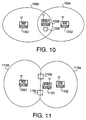
- FIG. 10 is a first conception view when the repeater according to the above embodiment 3 is employed in a cellular system;
- FIG. 11 is a second conception view when the repeater according to the above embodiment 3 is employed in a cellular system;
- FIG. 12 is a third conception view when the repeater according to the above embodiment 3 is employed in a cellular system;
- FIG. 13 is a schematic view illustrating the relationship between transmitting power of a base station as well as a repeater illustrated in FIG. 12 and a distance;
- FIG. 14 is a fourth conception view when the repeater according to the above embodiment 3 is employed in a cellular system;
- FIG. 15 is a block diagram illustrating a configuration of a three-dimensional channel selection adaptive array antenna applied to a base station of a mobile communication system according to an embodiment 4 of the present invention;
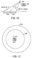
- FIG. 16 is an explanation view of three-dimensional directivity phase control operation for adding directivity to the three-dimensional channel selection adaptive array antenna in a vertical direction according to the above embodiment 4;
- FIG. 17 is a first conception view of a cell formed due to three-dimensional directivity phase control for adding directivity to the three-dimensional channel selection adaptive array antenna in a vertical direction according to the above-described embodiment 4;
- FIG. 18 is a conception view of a cell formed due to three-dimensional directivity phase control for adding directivity to the three-dimensional channel selection adaptive array antenna in horizontal/vertical direction according to the above-described embodiment 4; and
- FIG. 19 is a second conception view of a cell formed due to three-dimensional directivity phase control for adding directivity to the three-dimensional channel selection adaptive array antenna in a vertical direction according to the above-described embodiment 4.
-
- Embodiments of the present invention will be described specifically below with reference to accompanying drawings.
- FIG. 1 is a block diagram illustrating a configuration of a repeater applied to a mobile communication system according to an embodiment 1 of the present invention.
- A
repeater 100 illustrated in FIG. 1 is configured to be provided with adirectional antenna 101 for receiving a radio wave of a specific direction, a filter for filtering (extracting) predetermined signal from among signals received by thedirectional antenna 101, anamplifier 103 for amplifying signals passed through thefilter 102, and adirectional antenna 104 for transmitting the signal amplified by theamplifier 103 in a specific direction. - As to a
filter 102, when therepeater 100 is applied to FDMA (Frequency Division Multiple Access) system, a FDMA filter which passes through signals of only specific frequency is used. When therepeater 100 is applied to CDMA (Code Division Multiple Access) system, a CDMA filter which passes through only signals which are subjected to spreading with specific code by performing each processing of despreading, demodulation, spreading, and modulation is used. When therepeater 100 is applied to TDMA (Time Division Multiple Access) system, a TDMA filter which passes through signals during only specific time is used. In other words, thefilter 100 passes through only signals of predetermined channel. - An example in which such a
repeater 100 is used in a cellular system will be described referring to FIG. 2 to FIG. 4. However, the FDMA filter is used as thefilter 102. - As illustrated in FIG. 2, the
repeaters 201 to 204 are placed along circumference of thecell 206 formed by a radio wave of thebase station 205. Therepeaters 201 to 204 are set so as to pass only a frequency f1. Directional antennas of reception sides of therepeaters 201 to 204 are set in a direction of thebase station 205. - In this case, when the
base station 205 uses frequencies f1, f2, and f3, therepeaters 201 to 204 pass and amplify only a signal of the frequency f1. Consequently, since the signal of the frequency f1 reaches in the distance,radio wave areas 207 to 210 are formed in the outer side of thecell 206. - In FIG. 2, the
repeaters 201 to 204 are placed along circumference of thecell 206 with an interval of 90 degrees. In accordance with this placement, theradio wave areas 207 to 210 are formed independently due to therepeaters 201 to 204. However, it is also suitable that a radio wave area is formed in the outer side of thecell 206 over the whole circumference thereof while using more repeaters. - As illustrated in FIG. 3, a plurality of
repeaters 303 to 308 for passing frequencies f1 and f2 are formed along circumference of acell 302 formed by a radio wave of abase station 301. While a plurality ofrepeaters 311 to 316 for passing frequencies f3 and f4 are formed along circumference of acell 310 formed by a radio wave of abase station 309. Further,respective cells - In this case, on the supposition that both
base stations repeaters 303 to 308 pass and amplify only signals of the frequencies f1 and f2, the signals of the frequencies f1 and f2 reach in the distance, thus aradio wave area 317 of the frequencies f1 and f2 is formed in the outer side of thecell 302. - In the meantime, since the
repeaters 311 to 316 pass and amplify signals of the frequencies f3 and f4, the signals of the frequencies f3 and f4 reach in the distance, thus aradio wave area 318 of the frequencies f3 and f4 is formed in the outer side of thecell 310. - A relationship of this case between transmitting power of a signal transmitted by the
base station 301 and a distance will be described referring to FIG. 4. The transmitting power (transmission signal power) of signals corresponding to the frequencies f1 to f4 among signals transmitted by thebase station 301 is maintained at a value by which a mobile station can perform communication appropriately to a position d1 where therepeaters 303 to 308 are placed. Subsequently, with reference to the transmitting power of signals corresponding to the frequencies f3 and f4 among signals transmitted by thebase station 301, the transmitting power is attenuated to a value by which the mobile station becomes impossible to perform communication appropriately in an attenuation position d2. While with reference to the transmitting power of signals corresponding to the frequencies f1 and f2 transmitted by thebase station 301, since the transmitting power is amplified due to therepeaters 303 to 308, the transmitting power is attenuated to a value by which the mobile station becomes impossible to perform communication appropriately in an attenuation position d3 not the attenuation position d2. - Thus, according to the present embodiment, in FIG. 2, when the
base station 205 uses the frequencies f1, f2 and f3, since therepeaters 201 to 204 capable of passing through only the frequency f1, it is possible to pass and reached the signal of the frequency f1 in the distance. Namely, an area of a cell can be enlarged concerning only a specified channel. - Further, in FIG. 3, with reference to two
base stations repeaters 303 to 308, while the other side passes through the frequencies f3 and f4 with therepeaters 311 to 316. Both base stations use the frequencies f1 to f4 insmall areas large areas - Furthermore, the present embodiment is not required to use the amplifier with large amplification factor in a base station different from a conventional way, consequently, the size of the base station does not become large. A mobile station such as a portable telephone and so forth can perform communication while utilizing a radio area formed by repeaters with an original configuration, power consumption does not become large different from the conventional way.
- Moreover, since it is suitable that many base stations are not placed contrary to the conventional way, therefore, to secure of arranging places for the base station do not required. Since it is suitable that only repeaters are placed, it is possible to suppress equipment cost as the whole systems in comparison with a state where many base stations are placed.
- Now, GSM to be European Standard is mentioned as an example, in the GSM, 124 waves of frequencies exist. Since interference occurs when the same frequencies are employed in adjacent cells, thus 31 waves are used in every one cell, and the same frequency is used in every four cells so called as "reuse = 4". On the other hand, when the configuration of the above-described embodiment 1 is employed, in the inside of the cell formed by the base station, any base station can use 124 waves, further, 31 waves each become possible to be used according to only the cell formed due to the repeaters. For that reason, frequency utilization efficiency is improved remarkably.
- FIG. 5 is a block diagram illustrating a configuration of an adaptive repeater applied to a mobile communication system according to an
embodiment 2 of the present invention. - An
adaptive repeater 500 illustrated in FIG. 5 is configured to be provided with adirectional antenna 501 for receiving a radio wave in a specific direction, anadaptive filter 502 for filtering predetermined signal adaptively among signals received by thedirectional antenna 501, anamplifier 503 for amplifying signals passed through theadaptive filter 502, and adirectional antenna 504 for transmitting signals amplified by theamplifier 503 in a specific direction. - Adaptive control of signal filtering of the
adaptive filter 502 is one in which a parameter passing signals is possible to be changed arbitrarily. This control is performed through cable communications or radio communications from abase station 505. - For instance, if the
adaptive filter 502 is the FDMA filter, control is performed for changing frequencies to be passed, for instance, for changing the frequency f1 into the frequency f2 in every predetermined time. If theadaptive filter 502 is the CDMA filter, control is performed for changing specified codes to be passed, for instance, for changing the specified code c1 into the specified code c2 in every predetermined time. If theadaptive filter 502 is the TDMA filter, control is performed for changing signal passing time as well as signal passing time period and so forth. According to thisadaptive repeater 500, signals to be passed are capable of being changed in accordance with positions of respective mobile stations within a cell. - An example in which this sort of
adaptive repeater 500 is used for a cellular system will be described referring to FIG. 6 to FIG. 8. However, the FDMA filter is used as anadaptive filter 502. - As illustrated in FIG. 6,
adaptive repeaters 601 to 608 are placed along circumference of acell 610 formed by a radio wave of abase station 609. - Thus, when a plurality of
mobile stations 611 to 613 exist on the inside of thecell 610 of thebase station 609 and onemobile station 614 exists on the outside of the cell 610 (in the distance), abase station 505 controls adaptive filters of theadaptive repeaters 601 to 608 so as to pass, for instance, only a frequency f1. - According to this processing, a
radio wave area 615 in accordance with the frequency f1 is formed on the outside of thecell 610. Then, themobile station 614 becomes possible to perform communication appropriately while using this frequency f1. - Subsequently, as illustrated in FIG. 7, on the supposition that the
mobile stations 611 to 614 move to be come into the state where onemobile station 611 exists on the inside of thecell 610 of thebase station 609 and a plurality ofmobile stations 612 to 614 exist on the outside of thecell 610. - In this case, the
base station 609 controls the adaptive filters of theadaptive repeaters 601 to 608 so as to pass only the frequencies f1, f2 and f3 which a plurality of themobile stations 612 to 614 use. - According to this processing, a
radio wave area 701 in accordance with the frequencies f1 to f3 is formed on the outside of thecell 610, thus themobile stations 612 to 614 become possible to perform communication appropriately while employing the frequencies f1 to f3. - However, when a base station detects that a mobile station exists in the distance, since the mobile station transmits signals while synchronizing with a perch channel of the base station, the base station detects distance to the mobile station in such a way that the base station measures time required for back and forth between the mobile station and the perch channel. In another way, the base station detects distance of the mobile station therebetween in such a way that the base station measures reception power in reverse direction from the mobile station to the base station.
- Further, as illustrated in FIG. 8,
adaptive repeaters 801 to 803 are placed with a long distance, for instance, theadaptive repeaters 801 to 803 are placed with interval of 120 degrees along acell 805 of a base station 804. If the base station 804 controls so as to pass different frequencies f1, f2 or f3 in every each adaptive repeater f1, f2 or f3, it is possible to be performed communication while forming dedicatedradio wave areas 809 to 811 on the outside of thecell 805 of the base station 804 for the sake of respectivemobile stations 806 to 808 existing separately therefrom mutually. - Thus, according to the present embodiment, since the adaptive filters are used for the adaptive repeaters, when a mobile station exists on the outside of the cell (in the distance) formed in accordance with the base station, the present embodiment is possible to control operation such that only signals of frequency which the mobile station uses are amplified while passing through the adaptive filter of the adaptive repeater.
- Furthermore, the present embodiment is not required to use the amplifier with large amplification factor in a base station different from a conventional way, consequently, the size of the base station does not become large. Since a mobile station such as a portable telephone and so forth can perform communication while utilizing a radio area formed in accordance with adaptive repeaters with an original configuration as it is, power consumption does not become large contrary to the conventional way.
- Moreover, since it is suitable that many base stations are not placed contrary to the conventional way, thus, to secure arranging places for the base station is not required. Since it is suitable that only adaptive repeaters are placed, it is possible to suppress equipment cost as the whole systems in comparison with a state where many base stations are placed.
- FIG. 9 is a block diagram illustrating a configuration of an inverting repeater applied to a mobile communication system according to an embodiment 3 of the present invention.
- An inverting
repeater 900 illustrated in FIG. 9 is configured to be used an invertingamplifier 903 instead of theamplifier 103 of therepeater 100 illustrated in FIG. 1. - In this inverting
repeater 900, a frequency signal passed through afilter 102 is not only amplified by the invertingamplifier 903, but also inverted so as to come to opposite phase. For this reason, an input frequency is eliminated while denying mutually caused by addition of input/output frequency. Namely, signals received by anantenna 101 deny signals transmitted from anantenna 104 mutually. As a result, it is possible not to reach the input frequency beyond the invertingrepeater 900. - For instance, as illustrated in FIG. 10, when
adjacent cells adjacent base stations repeater 1005 is placed in a crossing area of thecells - In such a configuration, when a
mobile station 1006 performs a hand-over with movement from one side of thebase station 1001 to the otherside base station 1002 while existing in this crossing portion, themobile station 1006 should judge whether which of a reception signal from thebase station 1001 in reception at present and a reception signal from theadjacent base station 1002. - In this case, when the inverting
repeater 1005 sets to stop a traffic channel from thebase station 1002 in order to pass only a perch channel (control channel), themobile station 1006 is capable of performing above-described judgement from the perch channel. Further, in this case, since a traffic channel whose interference is not desired is stopped by the invertingrepeater 1005, themobile station 1006 is capable of performing the hand-over while performing appropriate talking with only the traffic channel of one frequency used. - Further, as illustrated in FIG. 11, in the case where
adjacent cells adjacent base stations adjacent cells repeaters cells - Furthermore, it is suitable to configure while employing an inverting
amplifier 903 instead of theamplifier 503 of therepeater 500 of theembodiment 2 illustrated in FIG. 5. - In this case, the inverting
amplifier 903 inverts only signals passed adaptively. According to this processing, it is possible to eliminate the passed frequency of signals. For instance, in FIG. 12, a plurality of invertingrepeaters 1203 to 1208 are placed along acell 1202 formed due to abase station 1201. If frequencies f3 and f4 among frequencies f1 to f4 employed in thebase station 1201 are stopped by the invertingrepeaters 1203 to 1208, acell 1209 in accordance with the frequencies f1 and f2 of the signals can be formed on the outside of thecell 1202. - Relationship of this case between transmitting power and a distance of the side of the
base station 1201 is illustrated in FIG. 13. Transmitting power (transmission signal power) of signals corresponding to frequencies f3 and f4 among signals transmitted by thebase station 1201 reaches to a position d1 where the invertingrepeaters 1201 to 1208 are placed. However, the transmitting power is attenuated to a value that is one in which a mobile station is impossible to perform communication appropriately. Further, transmitting power of signals corresponding to frequencies f1 and f2 among signals transmitted by thebase station 1201 is attenuated to a value that is one in which a mobile station is impossible to perform communication appropriately in an ordinary attenuation position d2. - Namely, it is possible to stop only a specified frequency by the inverting repeaters in accordance with inverse operation described above while referring to FIG. 5 to FIG. 8 in the
embodiment 2. Accordingly, it is possible to obtain the same effect as theembodiment 2 as things turned out. - Further, as illustrated in FIG. 14, a plurality of base stations 1403 to 1405 which use the same frequency f1 as a
base station 1401 are placed on the inside of aprimary cell 1402 formed due to thebase station 1401. If invertingrepeaters 1406 to 1408 with an invertingamplifier 903 are placed in between the base stations 1403 to 1405 and thebase station 1401, the frequency f1 of theprimary cell 1402 is stopped at the invertingrepeaters 1406 to 1408. A plurality of the base stations 1403 to 1405 capable of formingmicro cells 1409 to 1411 with the same frequency f1 respectively on the inside of theprimary cell 1402. - According to this processing, a mobile station can perform communication employing different signals with the same frequency f1 because the mobile station capable of performing communication employing the same frequency f1 to
different base stations 1401, 1403 to 1405. - Thus, according to the present embodiment, the frequency of the signal passed through the filter of the inverting repeater or the adaptive filter is inverted by the inverting
amplifier 903 so that the passed frequency is denied in the output side, therefore, it is possible to eliminate an input frequency of signals passed through a filter. Namely, it is possible not to reach a specific input frequency beyond the inverting repeater. - Further, the present embodiment is not required to employ the amplifier with large amplification factor in a base station different from a conventional way, consequently, the size of the base station does not become large. Since a mobile station such as a portable telephone and so forth can perform communication while utilizing a radio area formed in accordance with inverting repeaters with an original configuration as it is, thus power consumption does not become large contrary to the conventional way.
- Moreover, since it is suitable that many base stations are not placed contrary to the conventional way, to secure arranging places for the base station is not required. Since it is suitable that only inverting repeaters are placed, it is possible to suppress equipment cost as the whole systems in comparison with a state where many base stations are placed.
- FIG. 15 is a block diagram illustrating a configuration of a three-dimensional channel selection adaptive array antenna applied to a base station of a mobile communication system according to an embodiment 4 of the present invention.
- A three-dimensional channel selection adaptive array antenna 1500 (hereinafter referred to as only antenna) illustrated in FIG. 15 is configured to be provided with
filters modulators first phase shifters 1505 to 1508,second phase shifters 1509 to 1512,adders 1513 to 1516,antenna elements 1517 to 1520, ademodulator 1521, and a three-dimensional directivity phase controller 1522. - The
antenna elements 1517 to 1520 have a three-dimensional antenna structure. Specifically, this antenna element prepares the predetermined numbers of planes with a position relationship of approximately even with the ground. Theantenna elements 1517 to 1520 are configured while placing a plurality of antenna arrays on the respective planes. Here, respective planes are located in the direction of approximately vertical with the ground mutually with predetermined interval. Further, there is no limitation of arrangement method of a plurality of antenna arrays on respective planes, however, it is appropriate to place a plurality of antenna arrays regularly in respective antennas in view of easy operation. For instance, in the respective planes, a plurality of antenna arrays are placed in a line with predetermined intervals. While, a plurality of antenna arrays are placed so as to form a cross. - In the
filter 1501, the first to the N-th transmission data (f1 and f2) among the first to the M-th transmission data are passed through thefilter 1501 to be outputted to themodulator 1503. In thefilter 1502, the first to the M-th transmission data (f1, f2, f3 and f4) are passed through thefilter 1502 to be outputted to themodulator 1504. - In the
modulator 1503, the first to the N-th transmission data (f1 and f2) are modulated depending on a predetermined frequency of carrier (f1 or f2), before being outputted to thefirst phase shifters 1505 to 1508. In themodulator 1504, the first to the M-th transmission data (f1, f2, f3 and f4) are modulated depending on a predetermined frequency of carrier (any of f1 to f4), before being outputted to thesecond phase shifters 1509 to 1512. - The signals passed through the
first phase shifters 1505 to 1508 as well as passed through thesecond phase shifters 1509 to 1512 are added in theadders 1513 to 1516 to be transmitted through theantenna elements 1517 to 1521. - Further, signals received by the
antenna elements 1517 to 1520 are demodulated by thedemodulator 1521. The demodulated first to M-th reception data (f1, f2, f3 and f4) are outputted to the three dimensional directivity phase controller 1522. - The three-dimensional directivity phase controller 1522 performs control for adding predetermined directivity to signals from the
modulators first phase shifters 1505 to 1508 as well as thesecond phase shifters - As illustrated in FIG. 16, this control is to possess directivity with arbitrary angles 1 and 2 in vertical direction from an
antenna 1500 in high position, which theantenna 1500 is mounted on abase station 1601. According to this configuration, as illustrated in FIG. 17, it is possible to form inherent doughnut-shaped radio wave areas (cells) 1602 and 1603 in places respective near and far. - In this example, a signal area of frequencies f1 and f2 modulated depending on the first to the N-th transmission data is formed in an
outer side cell 1602. While a signal area of frequencies f1, f2, f3 and f4 modulated depending on the first to the M-th transmission data is formed in aninner side cell 1603. According to this processing, four frequencies can be used in thecell 1603, further different users are capable of re-using two frequencies f1 and f2 in thecell 1602. - Further, if control is performed such that directivity in horizontal/vertical direction is set, as illustrated in FIG. 18, a plurality of spot-shaped areas (cells) 1801 to 1804 are capable of being formed.
- Furthermore, as illustrated in FIG. 19, in two
base stations antenna 1500, it is also suitable that sells 1903 and 1904, andcells - Namely, in the
base station 1901, aninner side cell 1903 is formed by frequencies f1, f2, f3 and f4 of signals, while anouter side cell 1904 is formed by frequencies f3 and f4 of signals. Further, in thebase station 1902, aninner side cell 1905 is formed by the frequencies f1, f2, f3 and f4 of the signals so as not to cross to thecell 1903, while forming anouter side cell 1906 by the frequencies f1 and f2. According to this processing, in theinner side cell 1903 as well as in theinner side cell 1905, different users can use the frequencies f1, f2, f3 and f4. Further also in theouter side cell 1904, different users can use the frequencies f3 and f4, and also in theouter side cell 1906, different users can use the frequencies f1 and f2. For this reason, it is possible to improve frequency utilization efficiency. - Furthermore, it is also suitable that the
first phase shifters 1505 to 1508 as well as thesecond phase shifters 1509 to 1512 adds fixedly predetermined directivity to signals from themodulators - Thus, according to the present embodiment, directivity with arbitrary angles 1 and 2 in vertical direction from an antenna is set so that it is possible to form doughnut-shaped inherent radio wave areas (cells) in places respective near and far with the same frequency. Further, directivity is set in horizontal/vertical direction so that it is possible to form a plurality of spot-shaped areas (cells) using the same frequency. Consequently, it is possible to improve frequency utilization efficiency.
- As described-above, according to the present invention, it is possible to enlarge a radio wave area of a base station while suppressing the size increase of a base station, power consumption of a mobile station, the cost for the whole systems, and interference in adjacent cells.
- This application is based on the Japanese Patent Application No. HEI 11-094288 filed on March 31, 1999, entire content of which is expressly incorporated by reference herein.
- The present invention is utilized appropriately in a field of a digital mobile communication system.
Claims (16)
- A repeater apparatus comprising:reception means for receiving a radio wave;extraction means for extracting specific signals among signals received by said reception means;amplification means for amplifying the signals extracted by said extraction means; andtransmission means for transmitting the signals amplified by said amplification means.
- A repeater apparatus according to claim 1, wherein said extraction means extracts only signals of specific frequencies.
- A repeater apparatus according to claim 1, wherein said extraction means performs spreading processing on signals received by said reception means with a specific code and extracts only signals obtained by the spreading processing.
- A repeater apparatus according to claim 1, wherein said extraction means extracts signals in specific time.
- A repeater apparatus according to claim 1, wherein said extraction means changes signals to be extracted arbitrarily.
- A repeater apparatus according to claim 1, wherein said amplification means comprises inverting amplification means for amplifying signals so as to invert a phase of signals extracted by said extraction means.
- A mobile communication system placing a repeater apparatus according to claim 1 on an inside of a cell which is formed by a base station apparatus.
- A mobile communication system placing a repeater apparatus according to claim 1 on an outside of a cell which is formed by a base station apparatus.
- A mobile communication system placing a repeater apparatus according to claim 1 so that on outside of cells existing separately each other, which cells are formed by adjacent base station apparatuses, cells by specific signals used by the adjacent base station apparatuses are formed with the cells crossed each other.
- A mobile communication system placing a repeater apparatus according to claim 6 in cross area of cells which are formed by adjacent base station apparatus.
- A three-dimensional channel selection adaptive array antenna comprising:a three-dimensional adaptive array antenna in which a plurality of antenna elements are placed on predetermined numbers of respective planes with respective position relationships of approximately even with the ground;a plurality of filters for passing transmission signals which are different from mutually; andphase shift means for adding directivity to signals after modulation, which signals are different from mutually and are passed through said plurality of filters, such that said signals are radiated with arbitrary angles in a vertical direction when said signals are radiated from said three-dimensional adaptive array antenna.
- A three-dimensional channel selection adaptive array antenna according to claim 11, wherein said phase shift means adds directivity to signals after modulation, which signals are different from mutually and are passed through said plurality of filters, such that said signals are radiated with arbitrary angles in horizontal/ vertical direction when said signals are radiated from said three-dimensional adaptive array antenna.
- A three-dimensional channel selection adaptive array antenna according to claim 11, wherein there is provided a control means for controlling directivity added by said phase shift means according to reception signals of said three-dimensional adaptive array antenna.
- A base station apparatus while being provided with a three-dimensional channel selection adaptive array antenna, said three-dimensional channel selection adaptive array antenna comprising:a three-dimensional adaptive array antenna in which a plurality of antenna elements are placed on predetermined numbers of respective planes with respective position relationships of approximately even with the ground;a plurality of filters for passing transmission signals which are different from mutually; andphase shift means for adding directivity to signals after modulation, which signals are different from mutually and are passed through said plurality of filters, such that said signals are radiated with arbitrary angles in a vertical direction when said signals are radiated from said three-dimensional adaptive array antenna.
- A communication terminal apparatus for performing radio communication to a base station provided with a three-dimensional channel selection adaptive array antenna, said three-dimensional channel selection adaptive array antenna comprising:a three-dimensional adaptive array antenna in which a plurality of antenna elements are placed on predetermined numbers of respective planes with respective position relationships of approximately even with the ground;a plurality of filters for passing transmission signals which are different from mutually; andphase shift means for adding directivity to signals after modulation, which signals are different from mutually and are passed through said plurality of filters, such that said signals are radiated with arbitrary angles in a vertical direction when said signals are radiated from said three-dimensional adaptive array antenna.
- A channel selection transmission/reception method comprising the processes of:a reception process for receiving signals used in between a base station apparatus and a communication terminal apparatus;a extraction process for extracting signals of arbitrary channel from among signals received in said reception process; anda transmission process for amplifying to transmit the extracted signals.
Applications Claiming Priority (3)
| Application Number | Priority Date | Filing Date | Title |
|---|---|---|---|
| JP9428899 | 1999-03-31 | ||
| JP09428899A JP3544890B2 (en) | 1999-03-31 | 1999-03-31 | Mobile communication system |
| PCT/JP2000/001908 WO2000060767A1 (en) | 1999-03-31 | 2000-03-28 | Repeater |
Publications (1)
| Publication Number | Publication Date |
|---|---|
| EP1083681A1 true EP1083681A1 (en) | 2001-03-14 |
Family
ID=14106085
Family Applications (1)
| Application Number | Title | Priority Date | Filing Date |
|---|---|---|---|
| EP00911421A Withdrawn EP1083681A1 (en) | 1999-03-31 | 2000-03-28 | Repeater |
Country Status (8)
| Country | Link |
|---|---|
| US (1) | US6804491B1 (en) |
| EP (1) | EP1083681A1 (en) |
| JP (1) | JP3544890B2 (en) |
| KR (1) | KR20010043921A (en) |
| CN (1) | CN1157867C (en) |
| AU (1) | AU3330100A (en) |
| CA (1) | CA2333574C (en) |
| WO (1) | WO2000060767A1 (en) |
Cited By (2)
| Publication number | Priority date | Publication date | Assignee | Title |
|---|---|---|---|---|
| GB2425440A (en) * | 2005-04-22 | 2006-10-25 | Toshiba Res Europ Ltd | Circumferentially positioned bridging stations provide coverage around a base station |
| US8718541B2 (en) | 2007-12-31 | 2014-05-06 | Intel Corporation | Techniques for optimal location and configuration of infrastructure relay nodes in wireless networks |
Families Citing this family (28)
| Publication number | Priority date | Publication date | Assignee | Title |
|---|---|---|---|---|
| US20030068975A1 (en) * | 2001-08-06 | 2003-04-10 | The Research Foundation Of Suny | Integrated cellular and ad hoc relaying system |
| GB0200237D0 (en) * | 2002-01-07 | 2002-02-20 | Imec Inter Uni Micro Electr | Wireless cellular network architecture |
| KR100453620B1 (en) * | 2002-01-28 | 2004-10-20 | 주식회사 위다스 | Apparatus for detecting base station direction in RF repeater and method thereof |
| JP4217544B2 (en) * | 2003-06-05 | 2009-02-04 | 株式会社エヌ・ティ・ティ・ドコモ | Mobile communication system, control apparatus, and communication method |
| US7406295B1 (en) | 2003-09-10 | 2008-07-29 | Sprint Spectrum L.P. | Method for dynamically directing a wireless repeater |
| US7480486B1 (en) * | 2003-09-10 | 2009-01-20 | Sprint Spectrum L.P. | Wireless repeater and method for managing air interface communications |
| US20070129071A1 (en) * | 2003-10-24 | 2007-06-07 | Celletra Ltd. | Distributed cell balancing |
| US7415242B1 (en) * | 2003-11-10 | 2008-08-19 | Sprint Spectrum L.P. | Method and system for proximity detection for an in-building wireless repeater |
| US7362737B2 (en) | 2004-04-08 | 2008-04-22 | Tropos Networks, Inc. | Minimization of channel filters within wireless access nodes |
| KR101226347B1 (en) * | 2004-07-28 | 2013-01-24 | 닛본 덴끼 가부시끼가이샤 | Wireless transmission system |
| KR100578352B1 (en) | 2004-10-06 | 2006-05-11 | 주식회사 케이티프리텔 | Mobile communication service method and device using dedicated frequency in the whole building |
| US8144658B2 (en) * | 2005-02-11 | 2012-03-27 | Qualcomm Incorporated | Method and apparatus for mitigating interference in a wireless communication system |
| US7233770B2 (en) * | 2005-03-07 | 2007-06-19 | Harris Corporation | Communications system using separate receive and transmit frequency hopping hopsets |
| KR100855225B1 (en) | 2005-09-28 | 2008-08-29 | 삼성전자주식회사 | Frame communication apparatus and method in broadband wireless access communication system using multi-hop relay method |
| JP4784887B2 (en) * | 2006-04-28 | 2011-10-05 | 独立行政法人海上技術安全研究所 | Ship-to-shore base communication system |
| GB0624218D0 (en) * | 2006-12-04 | 2007-01-10 | Vodafone Plc | Base station repeater |
| FR2948252B1 (en) * | 2009-07-20 | 2011-09-16 | Commissariat Energie Atomique | METHOD FOR ALLOCATING TRANSMISSION RESOURCES IN A COOPERATIVE TYPE CELLULAR NETWORK |
| US8718542B2 (en) * | 2009-09-23 | 2014-05-06 | Powerwave Technologies S.A.R.L. | Co-location of a pico eNB and macro up-link repeater |
| US9780928B2 (en) | 2011-10-17 | 2017-10-03 | Golba Llc | Method and system for providing diversity in a network that utilizes distributed transceivers and array processing |
| TWM427521U (en) * | 2011-12-23 | 2012-04-21 | Tuton Technology Co Ltd | Lamp holder module with embedded signal booster |
| US9197982B2 (en) | 2012-08-08 | 2015-11-24 | Golba Llc | Method and system for distributed transceivers for distributed access points connectivity |
| US10321332B2 (en) | 2017-05-30 | 2019-06-11 | Movandi Corporation | Non-line-of-sight (NLOS) coverage for millimeter wave communication |
| US10484078B2 (en) | 2017-07-11 | 2019-11-19 | Movandi Corporation | Reconfigurable and modular active repeater device |
| US10348371B2 (en) | 2017-12-07 | 2019-07-09 | Movandi Corporation | Optimized multi-beam antenna array network with an extended radio frequency range |
| US10862559B2 (en) | 2017-12-08 | 2020-12-08 | Movandi Corporation | Signal cancellation in radio frequency (RF) device network |
| US10637159B2 (en) | 2018-02-26 | 2020-04-28 | Movandi Corporation | Waveguide antenna element-based beam forming phased array antenna system for millimeter wave communication |
| US11088457B2 (en) | 2018-02-26 | 2021-08-10 | Silicon Valley Bank | Waveguide antenna element based beam forming phased array antenna system for millimeter wave communication |
| JP2021141558A (en) * | 2020-03-05 | 2021-09-16 | パテントフレア株式会社 | Jamming mitigation device using phase difference interference |
Family Cites Families (19)
| Publication number | Priority date | Publication date | Assignee | Title |
|---|---|---|---|---|
| JPS5830774B2 (en) | 1979-05-04 | 1983-07-01 | 日本電信電話株式会社 | Wireless relay method |
| JPS6365723A (en) * | 1986-09-05 | 1988-03-24 | Mitsubishi Electric Corp | Mobile radio communication system |
| US5152002A (en) * | 1987-08-03 | 1992-09-29 | Orion Industries, Inc. | System and method for extending cell site coverage |
| US5168574A (en) * | 1987-08-03 | 1992-12-01 | Orion Industries, Inc. | System and method for switching between antennas in a radio frequency booster |
| US5179720A (en) * | 1990-02-23 | 1993-01-12 | Motorola, Inc. | Method and apparatus for extended coverage of a trunked radio communications system |
| US5218715A (en) * | 1991-01-15 | 1993-06-08 | Orion Industries, Inc. | Multi-donor booster operation and system |
| FI96655C (en) | 1992-12-17 | 1996-07-25 | Nokia Telecommunications Oy | Procedure for Maintaining a Group Call in a Radio Telephone System and System Controller and Subscriber Terminal for the Radio Telephone System |
| FR2703199B1 (en) * | 1993-03-26 | 1995-06-02 | Matra Communication | Radio transmission method using repeating spectrum inverting stations. |
| FI108098B (en) * | 1994-03-03 | 2001-11-15 | Nokia Networks Oy | Method for controlling a subscriber station, radio system and subscriber station operating on a direct channel |
| FI98034C (en) * | 1994-05-19 | 1997-03-25 | Nokia Telecommunications Oy | Method of forming a call in a mobile telephone system as well as a mobile telephone system |
| JP2747239B2 (en) | 1995-03-28 | 1998-05-06 | 日本電気移動通信株式会社 | Antenna device |
| US5890055A (en) * | 1995-07-28 | 1999-03-30 | Lucent Technologies Inc. | Method and system for connecting cells and microcells in a wireless communications network |
| US5970410A (en) * | 1996-02-27 | 1999-10-19 | Airnet Communications Corp. | Cellular system plan using in band-translators to enable efficient deployment of high capacity base transceiver systems |
| US6088592A (en) * | 1996-03-25 | 2000-07-11 | Airnet Communications Corporation | Wireless system plan using in band-translators with diversity backhaul to enable efficient depolyment of high capacity base transceiver systems |
| US5883884A (en) * | 1996-04-22 | 1999-03-16 | Roger F. Atkinson | Wireless digital communication system having hierarchical wireless repeaters with autonomous hand-off |
| FI103467B (en) * | 1996-07-25 | 1999-06-30 | Nokia Telecommunications Oy | Cell expansion in a time-division cellular system |
| CA2224035A1 (en) * | 1996-12-19 | 1998-06-19 | J. Leland Langston | Repeater node network system and method |
| US6122513A (en) * | 1997-11-06 | 2000-09-19 | Nortel Networks Corporation | Method for extending hard-handoff boundaries within a mobile telephone communications network |
| US6141533A (en) * | 1997-11-13 | 2000-10-31 | Motorola, Inc. | Method and apparatus for a mobile repeater |
-
1999
- 1999-03-31 JP JP09428899A patent/JP3544890B2/en not_active Expired - Fee Related
-
2000
- 2000-03-28 AU AU33301/00A patent/AU3330100A/en not_active Abandoned
- 2000-03-28 WO PCT/JP2000/001908 patent/WO2000060767A1/en not_active Ceased
- 2000-03-28 EP EP00911421A patent/EP1083681A1/en not_active Withdrawn
- 2000-03-28 CN CNB008003807A patent/CN1157867C/en not_active Expired - Fee Related
- 2000-03-28 US US09/701,337 patent/US6804491B1/en not_active Expired - Lifetime
- 2000-03-28 CA CA002333574A patent/CA2333574C/en not_active Expired - Fee Related
- 2000-03-28 KR KR1020007013452A patent/KR20010043921A/en not_active Ceased
Non-Patent Citations (1)
| Title |
|---|
| See references of WO0060767A1 * |
Cited By (3)
| Publication number | Priority date | Publication date | Assignee | Title |
|---|---|---|---|---|
| GB2425440A (en) * | 2005-04-22 | 2006-10-25 | Toshiba Res Europ Ltd | Circumferentially positioned bridging stations provide coverage around a base station |
| GB2425440B (en) * | 2005-04-22 | 2008-05-21 | Toshiba Res Europ Ltd | Wireless communications system |
| US8718541B2 (en) | 2007-12-31 | 2014-05-06 | Intel Corporation | Techniques for optimal location and configuration of infrastructure relay nodes in wireless networks |
Also Published As
| Publication number | Publication date |
|---|---|
| WO2000060767A1 (en) | 2000-10-12 |
| CA2333574A1 (en) | 2000-10-12 |
| JP2000286787A (en) | 2000-10-13 |
| JP3544890B2 (en) | 2004-07-21 |
| CN1297627A (en) | 2001-05-30 |
| US6804491B1 (en) | 2004-10-12 |
| AU3330100A (en) | 2000-10-23 |
| KR20010043921A (en) | 2001-05-25 |
| CA2333574C (en) | 2005-01-04 |
| CN1157867C (en) | 2004-07-14 |
Similar Documents
| Publication | Publication Date | Title |
|---|---|---|
| US6804491B1 (en) | Mobile communication system and repeater used in the mobile communication system | |
| FI105732B (en) | Radio communication systems realized with transmission stations equipped with frequency reversals | |
| US6895218B2 (en) | Method for in-building distribution using wireless access technology | |
| CA1260067A (en) | Mobile radio communication system with repeater station grid | |
| JP2884018B2 (en) | Wireless communication system and method of operating a wireless communication system | |
| US6374119B1 (en) | System and method for in-building mobile communications | |
| EP2091298A1 (en) | FDD inband backhauling and method thereof | |
| JPS62136930A (en) | mobile radio communication system | |
| JPH05259956A (en) | Radio repeater | |
| US20030211827A1 (en) | Repeater for radio communication system | |
| JP3419750B2 (en) | Automatic repeater for mobile radio communication | |
| US8503951B2 (en) | Antenna installation method in a multiple input multiple output communication method | |
| JP2981259B2 (en) | Same frequency radio repeater | |
| JP5052474B2 (en) | Repeater device | |
| US20020058476A1 (en) | Apparatus,system and method for transmitting upstream and downstream signals in a cellular communication system having a wireless backhaul | |
| JP3095126B2 (en) | Mobile radio frequency selective repeater | |
| CN218633944U (en) | 5G repeater for realizing full network communication | |
| CN111010217A (en) | Wireless repeater and method for realizing MIMO | |
| JPH0955697A (en) | Wireless communication system | |
| KR20000008468A (en) | Cdma mobile phone service system for special district | |
| JP2817125B2 (en) | Code division multiple access mobile communication system | |
| JPH05235819A (en) | Radio repeater | |
| JP2000031880A (en) | Wireless relay device | |
| JPH0613950A (en) | Wireless relay system | |
| JP2004120064A (en) | Relay system for mobile communication terminals |
Legal Events
| Date | Code | Title | Description |
|---|---|---|---|
| PUAI | Public reference made under article 153(3) epc to a published international application that has entered the european phase |
Free format text: ORIGINAL CODE: 0009012 |
|
| 17P | Request for examination filed |
Effective date: 20001228 |
|
| AK | Designated contracting states |
Kind code of ref document: A1 Designated state(s): AT BE CH CY DE DK ES FI FR GB GR IE IT LI LU MC NL PT SE |
|
| AX | Request for extension of the european patent |
Free format text: AL;LT;LV;MK;RO;SI |
|
| RBV | Designated contracting states (corrected) |
Designated state(s): DE FI FR GB SE |
|
| STAA | Information on the status of an ep patent application or granted ep patent |
Free format text: STATUS: THE APPLICATION HAS BEEN WITHDRAWN |
|
| 18W | Application withdrawn |
Effective date: 20050202 |