EP1083654A2 - Motor drive unit and method of detecting malfunction of the motor drive unit - Google Patents
Motor drive unit and method of detecting malfunction of the motor drive unit Download PDFInfo
- Publication number
- EP1083654A2 EP1083654A2 EP00119511A EP00119511A EP1083654A2 EP 1083654 A2 EP1083654 A2 EP 1083654A2 EP 00119511 A EP00119511 A EP 00119511A EP 00119511 A EP00119511 A EP 00119511A EP 1083654 A2 EP1083654 A2 EP 1083654A2
- Authority
- EP
- European Patent Office
- Prior art keywords
- motor
- electric motor
- malfunction
- sum
- switching elements
- Prior art date
- Legal status (The legal status is an assumption and is not a legal conclusion. Google has not performed a legal analysis and makes no representation as to the accuracy of the status listed.)
- Ceased
Links
Images




Classifications
-
- B—PERFORMING OPERATIONS; TRANSPORTING
- B62—LAND VEHICLES FOR TRAVELLING OTHERWISE THAN ON RAILS
- B62D—MOTOR VEHICLES; TRAILERS
- B62D5/00—Power-assisted or power-driven steering
- B62D5/04—Power-assisted or power-driven steering electrical, e.g. using an electric servo-motor connected to, or forming part of, the steering gear
-
- B—PERFORMING OPERATIONS; TRANSPORTING
- B62—LAND VEHICLES FOR TRAVELLING OTHERWISE THAN ON RAILS
- B62D—MOTOR VEHICLES; TRAILERS
- B62D5/00—Power-assisted or power-driven steering
- B62D5/04—Power-assisted or power-driven steering electrical, e.g. using an electric servo-motor connected to, or forming part of, the steering gear
- B62D5/0457—Power-assisted or power-driven steering electrical, e.g. using an electric servo-motor connected to, or forming part of, the steering gear characterised by control features of the drive means as such
- B62D5/0481—Power-assisted or power-driven steering electrical, e.g. using an electric servo-motor connected to, or forming part of, the steering gear characterised by control features of the drive means as such monitoring the steering system, e.g. failures
- B62D5/0487—Power-assisted or power-driven steering electrical, e.g. using an electric servo-motor connected to, or forming part of, the steering gear characterised by control features of the drive means as such monitoring the steering system, e.g. failures detecting motor faults
-
- H—ELECTRICITY
- H02—GENERATION; CONVERSION OR DISTRIBUTION OF ELECTRIC POWER
- H02H—EMERGENCY PROTECTIVE CIRCUIT ARRANGEMENTS
- H02H7/00—Emergency protective circuit arrangements specially adapted for specific types of electric machines or apparatus or for sectionalised protection of cable or line systems, and effecting automatic switching in the event of an undesired change from normal working conditions
- H02H7/08—Emergency protective circuit arrangements specially adapted for specific types of electric machines or apparatus or for sectionalised protection of cable or line systems, and effecting automatic switching in the event of an undesired change from normal working conditions for dynamo-electric motors
- H02H7/0833—Emergency protective circuit arrangements specially adapted for specific types of electric machines or apparatus or for sectionalised protection of cable or line systems, and effecting automatic switching in the event of an undesired change from normal working conditions for dynamo-electric motors for electric motors with control arrangements
- H02H7/0838—Emergency protective circuit arrangements specially adapted for specific types of electric machines or apparatus or for sectionalised protection of cable or line systems, and effecting automatic switching in the event of an undesired change from normal working conditions for dynamo-electric motors for electric motors with control arrangements with H-bridge circuit
-
- H—ELECTRICITY
- H02—GENERATION; CONVERSION OR DISTRIBUTION OF ELECTRIC POWER
- H02P—CONTROL OR REGULATION OF ELECTRIC MOTORS, ELECTRIC GENERATORS OR DYNAMO-ELECTRIC CONVERTERS; CONTROLLING TRANSFORMERS, REACTORS OR CHOKE COILS
- H02P7/00—Arrangements for regulating or controlling the speed or torque of electric DC motors
- H02P7/0094—Arrangements for regulating or controlling the speed or torque of electric DC motors wherein the position is detected using the ripple of the current caused by the commutator
-
- H—ELECTRICITY
- H02—GENERATION; CONVERSION OR DISTRIBUTION OF ELECTRIC POWER
- H02P—CONTROL OR REGULATION OF ELECTRIC MOTORS, ELECTRIC GENERATORS OR DYNAMO-ELECTRIC CONVERTERS; CONTROLLING TRANSFORMERS, REACTORS OR CHOKE COILS
- H02P7/00—Arrangements for regulating or controlling the speed or torque of electric DC motors
- H02P7/03—Arrangements for regulating or controlling the speed or torque of electric DC motors for controlling the direction of rotation of DC motors
- H02P7/04—Arrangements for regulating or controlling the speed or torque of electric DC motors for controlling the direction of rotation of DC motors by means of a H-bridge circuit
-
- Y—GENERAL TAGGING OF NEW TECHNOLOGICAL DEVELOPMENTS; GENERAL TAGGING OF CROSS-SECTIONAL TECHNOLOGIES SPANNING OVER SEVERAL SECTIONS OF THE IPC; TECHNICAL SUBJECTS COVERED BY FORMER USPC CROSS-REFERENCE ART COLLECTIONS [XRACs] AND DIGESTS
- Y10—TECHNICAL SUBJECTS COVERED BY FORMER USPC
- Y10S—TECHNICAL SUBJECTS COVERED BY FORMER USPC CROSS-REFERENCE ART COLLECTIONS [XRACs] AND DIGESTS
- Y10S388/00—Electricity: motor control systems
- Y10S388/90—Specific system operational feature
- Y10S388/903—Protective, e.g. voltage or current limit
Definitions
- the invention relates to a motor drive unit which controls an electric motor through pulse width modulation (PWM) control and to detection of a malfunction for the motor drive unit.
- PWM pulse width modulation
- the motor drive unit which controls an electric motor.
- the motor drive unit has a bridge circuit composed of four sides that each have a switching element.
- the electric motor has at least two ends connected to the switching elements that are diagonally positioned in relation to the bridge circuit. At least one of the switching elements is connected to a power line, and at least one of the other switching elements is grounded.
- the motor unit is driven by applying voltage to the power switching element. By performing pulse width modulation control of the switching elements, drive control of the electric motor is performed.
- a predetermined threshold value e.g. approximately 3% of the battery voltage
- the aforementioned motor drive unit takes into account nothing but the possibility of the portion between one terminal of the electric motor and the grounded line being short-circuited. Therefore, this motor drive unit is useless when there is a malfunction occurring in a motor drive device, a malfunction detection controller, or the like.
- the invention provides a motor drive unit and a method of detecting a malfunction thereof which make it possible to detect a wide variety of malfunctions relating to an electric motor by detecting various malfunctions in the electric motor, the motor drive device and the malfunction detection monitor device.
- a motor drive unit in accordance with a first exemplary embodiment of the present invention has a bridge circuit composed of four sides that each have a switching element.
- An electric motor having two ends is connected to the bridge circuit that is diagonally positioned in relation to the electric motor.
- At least one of the pair of switching elements is connected to a power line, and at least one of the other switching elements is grounded.
- the motor drive unit is driven by applying voltage to the power terminal. By performing pulse width modulation control of the switching elements, drive control of the electric motor is performed.
- the motor drive unit has a malfunction judging means for judging the occurrence of a malfunction when the sum of the terminal voltages of the electric motor is different from a power voltage by a predetermined value or more during operation of the electric motor.
- the sum Vm of terminal voltages Vm1, Vm2 at the ends of the electric motor is approximately equal to the power voltage Vb due to the operation of the bridge circuit. If the respective switching elements are short-circuited, the sum Vm assumes a value which is approximately equal to or greater than 3 ⁇ Vb/2 or a value which is approximately equal to or smaller than Vb/2.
- the malfunction judging means controller judges the occurrence of a malfunction when the sum of the terminal voltages of the electric motor is different from the power voltage by a predetermined value or more, various malfunctions as mentioned above are detected. Thus, it is possible to provide a suitable countermeasure against those malfunctions.
- a second exemplary embodiment of the invention is applied to a motor drive unit which controls the electric motor by using the bridge circuit as mentioned above.
- the motor drive unit has a malfunction judging means which judges the occurrence of a malfunction when the electric motor is out of operation and when the sum of the terminal voltages of the electric motor is different from the sum of voltage values which has been determined in advance based on the voltage values at the ends of the electric motor during a turned-off state of all the switching elements by a predetermined value or more.
- the sum Vm of the terminal voltages Vm1, Vm2 at the ends of the electric motor is equal to a predetermined voltage in a turned-off state of all the switching elements. For example, if the electric motor is grounded at one end through a pull-down resistor without connecting the electric motor at another end to the power line through a pull-up resistor, the sum Vm is equal to a ground voltage "0" (hereinafter referred to as a first mode).
- the sum Vm is equal to a value which is twice as great as a predetermined value between the power voltage Vb and the ground voltage "0" (equal to the power voltage Vb if the pull-up resistor and the pull-down resistor assume the same resistance value) (hereinafter referred to as a second mode).
- the electric motor is connected to the power line through the pull-up resistor without grounding the ends of the electric motor through the pull-down resistor, the sum Vm is equal to the power voltage 2 ⁇ Vb (hereinafter referred to as a third mode).
- the sum Vm is approximately equal to 2 ⁇ Vb or "0". Further, if portions between the ends of the electric motor and the power line or the grounded line have been short-circuited, the sum Vm is approximately equal to 2 ⁇ Vb or "0".
- the malfunction judging means controller judges the occurrence of a malfunction when the detected sum of the terminal voltages of the electric motor is different from the sum of voltage values which has been determined in advance based on the voltage values at the ends of the electric motor during a turned-off state of all the switching elements by at least a predetermined value.
- the motor drive unit has a malfunction judging means which approximately sets the terminal voltages at the ends of the electric motor to a lower power voltage during a turned-off state of all the switching elements by connecting at least one of the ends of the electric motor to the power line through the pull-up resistor and grounding at least the other end of the electric motor through the pull-down resistor and which judges the occurrence of a malfunction when the sum of the terminal voltages of the electric motor is different from the power voltage by a predetermined value or more.
- the sum Vm of the terminal voltages Vm1, Vm2 at the ends of the electric motor is approximately equal to the power voltage Vb due to the operation of the bridge circuit. Further, when the electric motor is out of operation, the sum Vm of the terminal voltages Vm1, Vm2 at the ends of the electric motor is approximately equal to the power voltage Vb due to the operation of the pull-up resistor and the pull-down resistor.
- the sum Vm assumes a value which is approximately equal to or greater than 3 ⁇ Vb/2 or a value which is approximately equal to or smaller than Vb/2. Further, while the electric motor is in operation, if portions between the ends of the electric motor and the grounded line or the power line have been short-circuited, the sum Vm assumes a value which is approximately equal to or greater than 3 ⁇ Vb/2 or a value which is approximately equal to or smaller than Vb/2. Further, while the electric motor is out of operation, if the switching elements of the bridge circuit have been short-circuited, the sum Vm is approximately equal to 2 ⁇ Vb or "0". Further, while the electric motor is out of operation, if portions between the ends of the electric motor and the power line or the grounded line have been short-circuited, the sum Vm is approximately equal to 2 ⁇ Vb or "0".
- the malfunction judging means judges the occurrence of a malfunction when the detected sum of the terminal voltages of the electric motor is different from the power voltage by at least a predetermined value.
- various malfunctions as mentioned above are detected. That is, a wide variety of malfunctions relating to the electric motor are detected, whereby it becomes possible to provide a suitable countermeasure against those malfunctions.
- the sum of the terminal voltages at the ends of the electric motor is set equal to the power voltage by means of the pull-up resistor and the pull-down resistor.
- the judgment of a malfunction occurring in marginal devices of the motor drive unit can be made with ease.
- a method of detecting a malfunction for a motor drive unit which has a bridge circuit composed of four sides including switching elements, an electric motor whose ends are connected to a pair of terminals at diagonal positions of the bridge circuit, a power circuit which applies a power voltage to a pair of terminals by connecting one of the terminals at the other diagonal positions to a power line and grounding the other terminal, and a motor drive device which controls the electric motor by performing pulse width modulation control of the switching elements.
- the sum of the terminal voltages of the electric motor is detected, and the occurrence of a malfunction in at least one of the bridge circuit, the electric motor and the motor drive device is judged if the sum of the terminal voltages of the electric motor is different from the power voltage by at least a predetermined value during operation of the electric motor.
- the sum of the terminal voltages of the electric motor is detected, and the occurrence of a malfunction in at least one of the bridge circuit, the electric motor and the motor drive device is judged when the electric motor is out of operation and when the sum of the terminal voltages of the electric motor is different from the sum of voltage values which has been determined in advance based on the voltage values at the ends of the electric motor during a turned-off state of all the switching elements by a predetermined value or more.
- terminal voltages at the ends of the electric motor are set to a lower power voltage during a turned-off state of all the switching elements by connecting at least one of the ends of the electric motor to the power line through a pull-up resistor and grounding at least the other of the ends of the electric motor through a pull-down resistor, and the sum of the terminal voltages of the electric motor is detected, and the occurrence of a malfunction in at least one of the bridge circuit, the electric motor and the motor drive device is judged if the sum of the terminal voltages of the electric motor is different from the power voltage by a predetermined value or more.
- FIG. 1 schematically shows a vehicular motor-driven power steering device to which a motor drive unit in accordance with the invention is applied.
- This motor-driven power steering device has a DC motor 10 serving as an electric motor.
- the DC motor 10 is mounted to an intermediate portion of a steering shaft 11 to rotate the steering shaft 11, and applies an assisting force to assist the steering of front wheels by rotational operation of a steering handle 12.
- a lower end portion of the steering shaft 11 is connected to a tie rod 14 in a steering gear box 13 in a manner allowing power transmission.
- the tie rod 14 is axially displaced due to rotation of an axis of the steering shaft 11.
- Front wheels (not shown) are steerably connected to the ends of the tie rod 14. The front wheels are laterally steered due to axial displacement of the tie rod 14.
- a steering torque sensor 21 is mounted to the steering shaft 11.
- the sensor 21 detects a steering torque Ts acting on the steering shaft 11, and supplies the detected steering torque Ts to a motor drive circuit 30.
- a vehicle speed sensor 22 for detecting a vehicle speed V, an engine speed sensor 23 for detecting an engine speed Ne, and a battery 24 are connected to the motor drive circuit 30.
- the motor drive circuit 30 has a bridge circuit 31 and a microcomputer 32.
- the bridge circuit 31 has four sides with switching elements SW1 through SW4 composed of a field effect transistor (FET).
- FET field effect transistor
- Reflux diodes D11 through D14 are connected in parallel to the switching elements SW1 through SW4.
- the switching elements SW1 through SW4 are controlled to be turned on and off by respective pulse-train signals from a gate control circuit 33.
- one of the terminals that is a junction point of the switching elements SW1, SW3 is connected to a battery 24 through a shunt resistor 34a and a relay switch circuit 35.
- the other terminal that is a junction point of the switching elements SW2, SW4 is grounded through a shunt resistor 34b.
- Resistance values of the shunt resistors 34a, 34b are set to relatively small values.
- a junction point of the switching elements SW1, SW2 and a junction point of the switching elements SW3, SW4, which are a pair of terminals located at bridge circuit 31, are connected to the ends of the DC motor 10 and grounded through pull-down resistors r1, r2.
- the shunt resistor 34b is connected at both ends to a motor current detection circuit 36.
- the detection circuit 36 detects a motor current Im flowing through the DC motor 10 by a voltage which is produced at both ends of the shunt resistor 34b, and supplies the detected motor current Im to the microcomputer 32.
- a low-pass filter composed of a resistor r3 and a capacitor C1 is connected to the pull-down resistor r1.
- the resistors r1, r3 and the capacitor C1 constitute a terminal voltage detection circuit 37.
- the terminal voltage detection circuit 37 which functions as a low-pass filter as described above, removes high-frequency components from the voltage Vm1' at one end of the DC motor 10 and supplies a first terminal voltage Vm1 to the microcomputer 32.
- a low-pass filter composed of a resistor r4 and a capacitor C2 is connected to the pull-down resistor r2.
- the resistors r2, r4 and the capacitor C2 constitute a terminal voltage detection circuit 38.
- the terminal voltage detection circuit 38 which also functions as a low-pass filter, removes high-frequency components from the voltage Vm2' at the other end of the DC motor 10 and supplies a second terminal voltage Vm2 to the microcomputer 32.
- the microcomputer 32 is supplied with a battery voltage Vb from the battery 24, a steering torque Ts from the steering torque sensor 21, a vehicle speed V from the vehicle speed sensor 22, and an engine speed Ne from the engine speed sensor 23.
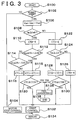
- the microcomputer 32 repeatedly executes a program shown in Fig. 3 at intervals of a predetermined short period, and controls operation of the DC motor 10 by supplying a pulse width modulation (PWM) control signal to the gate control circuit 33. Then, the microcomputer 32 detects a malfunction of the DC motor 10, the motor drive circuit 30, or the like. Upon detection of the malfunction, the microcomputer 32 also controls the relay switch circuit 35.
- PWM pulse width modulation
- the microcomputer 32 executes a program (not shown) and thereby determines whether to control the DC motor 10 in accordance with states of the battery 24 and the motor 10. If it is determined that the motor 10 may be controlled, the microcomputer 32 turns the relay switch circuit 35 on. Thus, a voltage from the battery 24 is supplied to the bridge circuit 31, the gate control circuit 33 through the relay switch circuit 35.
- the relay switch circuit 35 has been turned on. After the relay switch circuit 35 has been turned on, the microcomputer 32 starts executing the program shown in Fig. 3 at intervals of a predetermined short period.
- the execution of this program is started in STEP 100.
- an engine speed Ne from the engine speed sensor 23 is inputted to the microcomputer 32. Based on the inputted engine speed Ne, the microcomputer 32 determines whether to permit steering assist by the DC motor 10. If the engine speed Ne does not remain equal to or higher than a predetermined speed for more than a predetermined period, the result in STEP 102 is judged to be "NO". Then, the program proceeds to STEP 104. In STEP 104, the DC motor 10 is controlled to be stopped. In other words, assist control by the motor 10 is stopped. Then, the execution of this program is terminated in STEP 134.
- first and second terminal voltages Vm1, Vm2 are inputted from the terminal voltage detection circuits 37, 38.
- a motor current Im is inputted from the motor current detection circuit 36 in STEP 108. Depending whether or not the motor current Im is equal to or greater than a predetermined small current value Im0, it is determined whether or not the DC motor 10 is in operation.
- a second count value CT2 which is used to judge the occurrence of a malfunction when the DC motor 10 is out of operation, is reset to "0".
- STEPS 112, 114 whether or not the sum Vm of the terminal voltages is approximately equal to the battery voltage Vb. That is, it is determined in STEP 112 whether or not the sum Vm is equal to or greater than a value obtained by adding a predetermined voltage value ⁇ Vb to the battery voltage Vb, i.e., Vb + ⁇ Vb .
- a command current value I* for the DC motor 10 whose absolute value increases in accordance with an increase in absolute value
- PWM pulse width modulation
- the gate control circuit 33 In response to the control signal that has been supplied, the gate control circuit 33 outputs pulse-train signals for on-off control of the switching elements SW1 through SW4 to the switching elements SW1 through SW4.
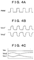
- a pulse-train signal PWM shown in Fig. 4A is supplied to the switching elements SW1, SW4. While the switching elements SW1, SW4 are controlled to be turned on and off in accordance with the pulse-train signal PWM, the switching elements SW2, SW3 remain turned off.
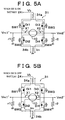
- the motor current Im flows from the battery 24 to the ground through the shunt resistor 34a, the switching element SW1, the DC motor 10, the switching element SW4 and the shunt resistor 34b, as indicated by a solid line in Fig. 5A.
- the motor current Im flows from the ground to the battery 24 through the shunt resistor 34b, a reflux diode D12, the DC motor 10, a reflux diode D13 and the shunt resistor 34a due to magnetic action of the electric motor, as indicated by a solid line in Fig. 5B.
- the voltages Vm1', Vm2' at the ends of the DC motor 10 have wave shapes as shown in Fig. 4B, and the first and second terminal voltages Vm1, Vm2, which are outputted from the terminal voltage detection circuits 37, 38 functioning as a low pass filter, have wave shapes as shown in Fig. 4C.
- Figs. 4B and 4C conceptualize the voltages Vm1', Vm2', Vm1 and Vm2 in an exaggerative manner.
- the pulse-train signal PWM shown in Fig. 4A is supplied to the switching elements SW2, SW3. While the switching elements SW2, SW3 are controlled to be turned on and off in accordance with the pulse-train signal PWM, the switching elements SW1, SW4 remain turned off.
- the pulse-train signal is at high level, the motor current Im flows from the battery 24 to the ground through the shunt resistor 34a, the switching element SW3, the DC motor 10, the switching element SW2 and the shunt resistor 34b, as indicated by a broken line in Fig. 5A.
- the motor current Im flows from the ground to the battery 24 through the shunt resistor 34b, a reflux diode D14, the DC motor 10, a reflux diode D11 and the shunt resistor 34a due to magnetic action of the electric motor 10, as indicated by a broken line in Fig. 5B.
- the voltages Vm1', Vm2' at the ends of the DC motor 10 have wave shapes in inverse relation to those shown in Fig. 4B
- the first and second terminal voltages Vm1, Vm2, which are outputted from the terminal voltage detection circuits 37, 38 functioning as a low pass filter, have wave shapes in inverse relation to those shown in Fig. 4C.
- the sum Vm of the first and second terminals Vm1, Vm2 is approximately equal to or greater than 3 ⁇ Vb/2 , or approximately equal to or smaller than Vb/2.
- the predetermined value ⁇ Vb in STEPS 112, 114 is set to a value smaller than Vb/2, it is possible to detect a malfunction as described in the examples (1) through (8).
- the first count value CT1 increases through the processing in STEP 118 every time this program is executed. If the count value CT1 becomes equal to or greater than the predetermined value CT10 due to an increase in the first count value CT1, the result in STEP 120 is judged to be "YES”. Then, the program proceeds to STEP 136 and the subsequent STEPS.
- STEP 136 operation control of the DC motor 10 is stopped, and the relay switch circuit 35 is turned off. Then, a warning lamp (not shown) is lit up, and a fail processing, for example, of recording a state of malfunction that has occurred as a diagnostic code is performed. Then, execution of this program is terminated in STEP 138. In this case, unlike the case with the aforementioned processing in STEP 134, this program is not executed again after the processing in STEP 138. In this case, it is also possible to prohibit only the processing of driving the DC motor 10 and continue the processings in the program as usual.
- the second count value CT2 increases through the processing in STEP 128 every time this program is executed. If the count value CT2 becomes equal to or greater than the predetermined value CT20 due to an increase in the second count value CT2, the result in STEP 130 is judged to be "YES”. Then, the program proceeds to STEP 136 and the subsequent STEPS.
- this modification example dispenses with the pull-down resistor r1 of the aforementioned embodiment. Instead, the DC motor 10 is connected at one end to the power line of the battery 24 through a pull-up resistor r5.
- the construction of the circuit of this modification example is the same as that of the aforementioned embodiment.
- the switching elements SW1, SW4 or the switching elements SW2, SW3 in the bridge circuit 31 are controlled to be turned on and off, whereby operation of the DC motor 10 is controlled.
- the operation is substantially the same as in the aforementioned embodiment. That is, the voltages Vm1', Vm2' at the ends of the motor 10 are alternately switched between a value which is approximately equal to "0" and a value which is approximately equal to Vb, and the sum Vm of the first and second terminal voltages Vm1, Vm2 is also approximately equal to Vb. If a malfunction as described in the examples (1) through (3) occurs during operation of the DC motor 10, the voltages Vm1', Vm2' at the ends of the motor 10 and the sum Vm of the first and second terminal voltages Vm1, Vm2 assume the values mentioned in the examples (1) through (3).
- the microcomputer 32 omits the processings of STEPS 108, 110 and 122 through 130 shown in Fig. 3, and performs the processing of STEP 112 immediately after the processing of STEP 106.
- the microcomputer 32 may be designed to execute a program composed of STEPS 100 through 106, 112 through 120, and 132 through 138.
- this modification example also dispenses with the motor current detection circuit 36. As a result, in addition to the effects of the aforementioned embodiment, this modification example makes it possible to detect a much wider variety of malfunctions through simple processings.
- this modification example may be designed as shown in Fig. 7. That is, it is also possible to ground one end of the DC motor 10 through the pull-down resistor r1 as in the aforementioned embodiment or to connect the other end of the DC motor 10 to the power line of the battery 24 through the pull-up resistor r6. This also makes it possible to achieve substantially the same effects as those of the modification example by executing a program similar to that of the modification example.
- the switching elements SW1, SW4 or the switching elements SW2, SW3 of the bridge circuit 31 are controlled to be turned on and off.
- the operation is substantially the same as in the aforementioned embodiment. That is, the voltages Vm1', Vm2' at the ends of the motor 10 are alternately switched between a value which is approximately equal to "0" and a value which is approximately equal to Vb, and the sum Vm of the first and second terminal voltages Vm1, Vm2 is also approximately equal to Vb.
- this modification example may be designed to determine in STEP 124 of the program shown in Fig. 3 whether or not the sum Vm of the first and second terminal voltages Vm1, Vm2 has deviated from 2 ⁇ Vb by a predetermined value or more.
- the processing of judgment in STEP 124 may be changed into the processing of determining whether or not the sum Vm is equal to or greater than a value obtained by adding the predetermined voltage value ⁇ Vb to 2 ⁇ Vb, i.e., 2 ⁇ Vb + ⁇ Vb and the processing of determining whether or not the sum Vm is equal to or smaller than a value obtained by subtracting the predetermined voltage value ⁇ Vb from 2 ⁇ Vb, i.e., 2 ⁇ Vb - ⁇ Vb , as in the aforementioned STEPS 112, 114.
- the motor current Im is detected by detecting voltages at both ends of the shunt resistor 34b.
- detection of the motor current Im may also be carried out such that voltages at both ends of the shunt resistor 34a are conducted into the motor current detection circuit 3.
- the motor current Im is detected based on the voltage drop by the resistor.
- a non-contact type current sensor such as a hall device to a contact position of the resistor, i.e., to a position where the motor current Im flows, and detect the motor current Im by means of the sensor.
- the first and second terminal voltages Vm1, Vm2 of the DC motor 10 are inputted to the microcomputer 32, and the sum Vm of the terminal voltages is calculated through the processing of STEP 106 (Fig. 3) performed by the computer 32.
- an adder which summates the first and second terminal voltages Vm1, Vm2 and outputs the sum Vm of both the terminal voltages Vm1, Vm2, between the terminal voltage detection circuits 37, 38 and the microcomputer 32, and input the sum Vm of the first and second terminal voltages Vm1, Vm2 to the microcomputer 32 simply from the adder in STEP 106.
- the invention is preferably implemented on a programmed general purpose computer 30.
- the entire invention, the malfunction judgment controller, operation judgment controller, continuation detection controller and/or failure processing controller can also be implemented on a special purpose computer, a programmed microprocessor or micro-controller and peripheral integrated circuit elements, an ASIC or other integrated circuit, a digital signal processor, a hardwired electronic or logic circuit such as a discrete element circuit, a programmable logic device such as a PLD, PLA, FPGA or PAL, or the like.
- any device capable of implementing a finite state machine that is in turn capable of implementing the flowcharts shown in Fig. 3, can be used to implement the malfunction judgment controller, operation judgment controller, continuation detection controller and failure processing controller.
- a DC motor (10) is connected to diagonal positions of a bridge circuit (31) having four sides including switching elements (SW1-SW4) and reflux diodes (Di1-Di4). At least one of two terminals is connected to a power line, and at least the other terminal is grounded. By performing pulse width modulation control of the switching elements, operation of the DC motor (10) is controlled. When the DC motor (10) is in operation, the sum of the terminal voltages of the DC motor (10) is equal to the power voltage. When the DC motor (10) is out of operation, the sum of the voltages is set to a predetermined voltage. If the sum of the voltages has deviated from the power voltage or the predetermined voltage by at least a predetermined value, the occurrence of a malfunction is judged.
- SW1-SW4 switching elements
- Di1-Di4 reflux diodes
Landscapes
- Engineering & Computer Science (AREA)
- Power Engineering (AREA)
- Chemical & Material Sciences (AREA)
- Combustion & Propulsion (AREA)
- Transportation (AREA)
- Mechanical Engineering (AREA)
- Control Of Direct Current Motors (AREA)
- Power Steering Mechanism (AREA)
- Control Of Motors That Do Not Use Commutators (AREA)
Abstract
Description
Claims (7)
- A motor drive unit having a bridge circuit (31) having four sides that each have a switching element, an electric motor (10) having two ends connected to the bridge circuit (31) and a motor drive device (30) which operates the electric motor (10) by connecting one of the switching elements to a power line and grounding an other one of the switching elements and which controls the electric motor (10) by performing pulse width modulation control of the switching elements, the motor drive unit characterized by comprising:a malfunction judging means (S112, S114, 32) for judging the occurrence of a malfunction in at least one of the bridge circuit (31), the electric motor (10) and the motor drive device (30) when a sum of voltages at the two ends of the electric motor is different from the power voltage at the power line by a at least a predetermined value during operation of the electric motor (10).
- A motor drive unit having a bridge circuit (31) having four sides that each have a switching element, an electric motor (10) having two ends connected to the bridge circuit and a motor drive device (30) which operates the electric motor (10) by connecting one of the switching elements to a power line and grounding an other one of the switching elements and which controls the electric motor by performing pulse width modulation control of the switching elements, the motor drive unit characterized by comprising:a malfunction judging means (S124, 32) for judging the occurrence of a malfunction in at least one of the bridge circuit (31), the electric motor (10) and the motor drive device (30) when the electric motor (10) is out of operation when a sum of voltages at the two ends of the electric motor (10) is different by at least a predetermined value from a sum of voltage values which were determined in advance based on the voltage values at the two ends of the electric motor (10) during a turned-off state of all the switching elements.
- A motor drive unit having a bridge circuit (31) having four sides that each have a switching element, an electric motor (10) having two ends connected to the bridging circuit and a motor drive device (30) which operates the electric motor (10) by connecting one of switching elements to a power line and grounding an other one of the switching elements and which controls the electric motor (10) by performing pulse width modulation control of the switching elements, the motor drive unit characterized by comprising:a circuit which sets terminal voltages at the two ends of the electric motor (10) to half of power voltage during a turned-off state of all the switching elements, wherein the circuit comprises:a pull-up resistor (r5, r6) connected to at least one of the two ends of the electric motor (10) and to the power line; anda pull-down resistor (r1, s2) connected to at least the other of the two ends of the electric motor (10) and to the ground; anda malfunction judging means (S112, S114, S124, 32) for judging the occurrence of a malfunction in at least one of the bridge circuit (31), the electric motor (10) and the motor drive device (30) when a sum of the voltages at the ends of the electric motor (10) is different by a predetermined value from the power voltage at the power line during operation of the electric motor (10).
- The motor drive unit as claims in either of claims 1 and 2, characterized by further comprising:a current detecting means (36) for detecting a current flowing through the electric motor (10); andan operation judging means (S108, 32) for judging, based on the detected current, whether the electric motor (10) is in operation or out of operation.
- The motor drive unit as claims in any of claims 1 to 4, characterized by further comprising:a continuation detecting means (S120, S130, 32) for detecting whether or not the malfunction judging means (S112, S114, S124, 32) continuously judges the occurrence of a malfunction; anda failure processing means (S136, 32) for performing failure processing if the malfunction continues for a predetermined period.
- The motor drive unit according to claim 5, characterized in that:the failure processing includes at least one of stopping operating the electric motor, issuing a warning, and recording a type of the malfunction as a diagnosis code.
- A motor drive unit as claims in any of claims 1 to 6, characterized in that:the sum of voltages is the sum of a first terminal voltage filtered out at one end of the electric motor and a second terminal voltage filtered out at the other end of the electric motor (10).
Applications Claiming Priority (2)
| Application Number | Priority Date | Filing Date | Title |
|---|---|---|---|
| JP25259399 | 1999-09-07 | ||
| JP25259399A JP3292179B2 (en) | 1999-09-07 | 1999-09-07 | Abnormality detection device for motor drive device |
Publications (2)
| Publication Number | Publication Date |
|---|---|
| EP1083654A2 true EP1083654A2 (en) | 2001-03-14 |
| EP1083654A3 EP1083654A3 (en) | 2004-03-24 |
Family
ID=17239537
Family Applications (1)
| Application Number | Title | Priority Date | Filing Date |
|---|---|---|---|
| EP20000119511 Ceased EP1083654A3 (en) | 1999-09-07 | 2000-09-06 | Motor drive unit and method of detecting malfunction of the motor drive unit |
Country Status (5)
| Country | Link |
|---|---|
| US (1) | US6335600B1 (en) |
| EP (1) | EP1083654A3 (en) |
| JP (1) | JP3292179B2 (en) |
| KR (1) | KR100386174B1 (en) |
| CN (1) | CN1182987C (en) |
Cited By (6)
| Publication number | Priority date | Publication date | Assignee | Title |
|---|---|---|---|---|
| EP1372257A3 (en) * | 2002-06-10 | 2004-12-29 | Alps Electric Co., Ltd. | Diagnostic device for electric mechanism drive circuits |
| WO2006108535A1 (en) * | 2005-04-13 | 2006-10-19 | Ab Skf | Assembly comprising a three-phase machine and a frequency converter |
| WO2008003534A1 (en) * | 2006-07-03 | 2008-01-10 | Continental Automotive Gmbh | Method and device for recognition of a short circuit in a circuit arrangement |
| EP1826891A3 (en) * | 2006-02-27 | 2008-05-14 | Matsushita Electric Works, Ltd. | Control drive circuit for electric power tool |
| FR2993059A1 (en) * | 2012-07-04 | 2014-01-10 | Bosch Gmbh Robert | POWER STAGE AND METHOD OF MANAGING THE SAME |
| FR2998117A1 (en) * | 2012-11-14 | 2014-05-16 | Mitsubishi Electric Corp | MOTOR CONTROL DEVICE, MOTOR CONTROL METHOD, AND ELECTRIC POWER STEERING DEVICE |
Families Citing this family (31)
| Publication number | Priority date | Publication date | Assignee | Title |
|---|---|---|---|---|
| JP4508320B2 (en) * | 1999-10-01 | 2010-07-21 | 株式会社ミクニ | Failure determination device for electromagnetic coil operating device |
| US7301296B1 (en) * | 2001-07-23 | 2007-11-27 | Rockwell Automation Technologies, Inc. | Integrated control and diagnostics system |
| US6750622B2 (en) * | 2000-05-05 | 2004-06-15 | Advanced Materials Corporation | Motor controller system for battery-powered motors |
| US7265516B2 (en) * | 2001-12-13 | 2007-09-04 | Lacroix Michael Charles | Linear electric motor controller and system for providing linear control |
| DE10339363B4 (en) * | 2003-08-27 | 2011-02-03 | K.A. Schmersal Gmbh & Co | Access protection device for a room area |
| US20050264253A1 (en) * | 2003-10-21 | 2005-12-01 | Mladen Ivankovic | Linear power module |
| JP4506263B2 (en) * | 2004-04-30 | 2010-07-21 | 日本精工株式会社 | Control device for electric power steering device |
| US7091739B2 (en) * | 2004-06-25 | 2006-08-15 | General Electric Company | System and method for detecting an operational fault condition in a power supply |
| JP2006081327A (en) * | 2004-09-10 | 2006-03-23 | Mitsubishi Electric Corp | Inverter failure detection device |
| JP4628825B2 (en) * | 2005-03-11 | 2011-02-09 | 本田技研工業株式会社 | Vehicle steering system |
| US7064509B1 (en) | 2005-03-14 | 2006-06-20 | Visteon Global Technologies, Inc. | Apparatus for DC motor position detection with capacitive ripple current extraction |
| JP2007060762A (en) * | 2005-08-23 | 2007-03-08 | Mitsubishi Electric Corp | Fault detection device for load drive system |
| US7342369B2 (en) * | 2006-02-17 | 2008-03-11 | Lear Corporation | Differential ripple detection method and system |
| JP4741391B2 (en) * | 2006-03-09 | 2011-08-03 | オムロンオートモーティブエレクトロニクス株式会社 | Ground fault detection device for motor drive circuit |
| DE102007004094A1 (en) * | 2007-01-26 | 2008-08-07 | Siemens Ag | Method and device for controlling a pulse-width modulation controllable three-phase machine with a plurality of phase windings |
| KR100835194B1 (en) * | 2007-05-29 | 2008-06-04 | 주식회사 만도 | Inverter switch error detection method in electric power steering system |
| DE102008001025A1 (en) * | 2008-04-07 | 2009-10-08 | Robert Bosch Gmbh | Method and device for current measurement in phase lines |
| US8193746B2 (en) * | 2008-05-23 | 2012-06-05 | Lear Corporation | Automotive electric motor speed control system |
| CN101821938B (en) * | 2008-10-20 | 2012-09-19 | 丰田自动车株式会社 | motor control unit |
| US20120228041A1 (en) * | 2009-11-13 | 2012-09-13 | Positec Power Tools (Suzhou) Co., Ltd. | Lawn mower |
| JP5641638B2 (en) * | 2010-02-03 | 2014-12-17 | ローム株式会社 | Abnormality detection circuit, load drive device, electrical equipment |
| WO2014184888A1 (en) * | 2013-05-15 | 2014-11-20 | 三菱電機株式会社 | Electric power steering device |
| US9929684B2 (en) * | 2013-08-23 | 2018-03-27 | Marvell International Ltd. | Motor control system and method of controlling a motor |
| SK500132014A3 (en) * | 2014-02-11 | 2016-03-01 | Ladislav Grno | The sensor and method for electric current measuring |
| JP6237565B2 (en) * | 2014-10-17 | 2017-11-29 | 株式会社デンソー | Rotating electrical machine control device and electric power steering device using the same |
| DE102017202191A1 (en) * | 2017-02-13 | 2018-08-16 | Robert Bosch Gmbh | Circuit and method for detecting a creeping short circuit in bridge circuits |
| JP7127373B2 (en) * | 2018-06-12 | 2022-08-30 | 日立金属株式会社 | detector |
| DE102019210566B4 (en) * | 2019-07-17 | 2022-03-17 | Conti Temic Microelectronic Gmbh | Apparatus and method for measuring current flowing through a PWM-driven inductive load |
| CN115085633B (en) * | 2022-07-05 | 2026-03-03 | 一汽解放汽车有限公司 | Motor control method, apparatus, computer device, and storage medium |
| CN115986686A (en) * | 2022-11-09 | 2023-04-18 | 小华半导体有限公司 | H bridge dead zone protection circuit |
| DE102022213311A1 (en) | 2022-12-08 | 2024-06-13 | Robert Bosch Gesellschaft mit beschränkter Haftung | H-bridge circuit for supplying current to an inductor |
Family Cites Families (5)
| Publication number | Priority date | Publication date | Assignee | Title |
|---|---|---|---|---|
| US4924158A (en) * | 1989-04-03 | 1990-05-08 | General Motors Corporation | Motor driver protection circuit |
| JP2659108B2 (en) * | 1991-04-26 | 1997-09-30 | 本田技研工業株式会社 | Motor drive control device |
| JP3214061B2 (en) * | 1991-11-11 | 2001-10-02 | オムロン株式会社 | Motor drive device for electric power steering device |
| WO1998058833A1 (en) * | 1997-06-20 | 1998-12-30 | Mitsubishi Denki Kabushiki Kaisha | Motor driven power steering device |
| JP3696384B2 (en) * | 1997-09-16 | 2005-09-14 | 本田技研工業株式会社 | Electric motor drive |
-
1999
- 1999-09-07 JP JP25259399A patent/JP3292179B2/en not_active Expired - Fee Related
-
2000
- 2000-09-06 US US09/655,916 patent/US6335600B1/en not_active Expired - Fee Related
- 2000-09-06 KR KR10-2000-0052744A patent/KR100386174B1/en not_active Expired - Fee Related
- 2000-09-06 EP EP20000119511 patent/EP1083654A3/en not_active Ceased
- 2000-09-07 CN CNB001263382A patent/CN1182987C/en not_active Expired - Fee Related
Cited By (8)
| Publication number | Priority date | Publication date | Assignee | Title |
|---|---|---|---|---|
| EP1372257A3 (en) * | 2002-06-10 | 2004-12-29 | Alps Electric Co., Ltd. | Diagnostic device for electric mechanism drive circuits |
| WO2006108535A1 (en) * | 2005-04-13 | 2006-10-19 | Ab Skf | Assembly comprising a three-phase machine and a frequency converter |
| US7948206B2 (en) | 2005-04-13 | 2011-05-24 | Ab Skf | Assembly comprising a three-phase machine and a frequency converter |
| EP1826891A3 (en) * | 2006-02-27 | 2008-05-14 | Matsushita Electric Works, Ltd. | Control drive circuit for electric power tool |
| US7570000B2 (en) | 2006-02-27 | 2009-08-04 | Matsushita Electric Works, Ltd. | Control drive circuit for electric power tool |
| WO2008003534A1 (en) * | 2006-07-03 | 2008-01-10 | Continental Automotive Gmbh | Method and device for recognition of a short circuit in a circuit arrangement |
| FR2993059A1 (en) * | 2012-07-04 | 2014-01-10 | Bosch Gmbh Robert | POWER STAGE AND METHOD OF MANAGING THE SAME |
| FR2998117A1 (en) * | 2012-11-14 | 2014-05-16 | Mitsubishi Electric Corp | MOTOR CONTROL DEVICE, MOTOR CONTROL METHOD, AND ELECTRIC POWER STEERING DEVICE |
Also Published As
| Publication number | Publication date |
|---|---|
| CN1182987C (en) | 2005-01-05 |
| JP3292179B2 (en) | 2002-06-17 |
| KR20010050357A (en) | 2001-06-15 |
| EP1083654A3 (en) | 2004-03-24 |
| US6335600B1 (en) | 2002-01-01 |
| CN1287930A (en) | 2001-03-21 |
| KR100386174B1 (en) | 2003-06-02 |
| JP2001078480A (en) | 2001-03-23 |
Similar Documents
| Publication | Publication Date | Title |
|---|---|---|
| EP1083654A2 (en) | Motor drive unit and method of detecting malfunction of the motor drive unit | |
| JP3518944B2 (en) | Motor drive | |
| JP2944867B2 (en) | Electric power steering control device | |
| US4532567A (en) | Electric power steering stall protection circuit | |
| US5659472A (en) | Motor controller | |
| JPWO1998058833A1 (en) | Electric power steering device | |
| WO1998058833A1 (en) | Motor driven power steering device | |
| JP3285490B2 (en) | Electric power steering device | |
| EP1738990B1 (en) | Voltage boosting circuit and electrically-driven power steering device | |
| CA2355019C (en) | Electrically-driven power steering system having failure detection function | |
| DE60113612T2 (en) | Wiper control apparatus | |
| JPH05185937A (en) | Motor drive device for motor-driven power steering device | |
| JP3166397B2 (en) | Electric power steering device | |
| JP3572973B2 (en) | Motor control device | |
| JP5125432B2 (en) | Control device for electric power steering device and control device for motor | |
| JP2914132B2 (en) | Electric power steering device with electromagnetic clutch | |
| US4991676A (en) | Motorized power steering apparatus | |
| JP3229519B2 (en) | Electric power steering device | |
| JP3641921B2 (en) | Control device for electric power steering device | |
| JP3875222B2 (en) | Vehicle steering control device | |
| KR100330447B1 (en) | Motor driven power steering device | |
| JP3831129B2 (en) | Electric motor drive | |
| JP2003033082A (en) | Motor drive | |
| JPH11341851A (en) | Malfunction detecting apparatus of motor | |
| JPH06127418A (en) | Control device at abnormality for rear wheel steering device of vehicle |
Legal Events
| Date | Code | Title | Description |
|---|---|---|---|
| PUAI | Public reference made under article 153(3) epc to a published international application that has entered the european phase |
Free format text: ORIGINAL CODE: 0009012 |
|
| 17P | Request for examination filed |
Effective date: 20000906 |
|
| AK | Designated contracting states |
Kind code of ref document: A2 Designated state(s): AT BE CH CY DE DK ES FI FR GB GR IE IT LI LU MC NL PT SE |
|
| AX | Request for extension of the european patent |
Free format text: AL;LT;LV;MK;RO;SI |
|
| PUAL | Search report despatched |
Free format text: ORIGINAL CODE: 0009013 |
|
| AK | Designated contracting states |
Kind code of ref document: A3 Designated state(s): AT BE CH CY DE DK ES FI FR GB GR IE IT LI LU MC NL PT SE |
|
| AX | Request for extension of the european patent |
Extension state: AL LT LV MK RO SI |
|
| RIC1 | Information provided on ipc code assigned before grant |
Ipc: 7B 62D 5/04 B Ipc: 7H 02H 7/122 A |
|
| 17Q | First examination report despatched |
Effective date: 20040525 |
|
| AKX | Designation fees paid |
Designated state(s): DE FR GB |
|
| APBN | Date of receipt of notice of appeal recorded |
Free format text: ORIGINAL CODE: EPIDOSNNOA2E |
|
| APBR | Date of receipt of statement of grounds of appeal recorded |
Free format text: ORIGINAL CODE: EPIDOSNNOA3E |
|
| APAF | Appeal reference modified |
Free format text: ORIGINAL CODE: EPIDOSCREFNE |
|
| APBT | Appeal procedure closed |
Free format text: ORIGINAL CODE: EPIDOSNNOA9E |
|
| STAA | Information on the status of an ep patent application or granted ep patent |
Free format text: STATUS: THE APPLICATION HAS BEEN REFUSED |
|
| 18R | Application refused |
Effective date: 20100508 |