EP1083633A2 - Connecting terminal for a flat circuit - Google Patents
Connecting terminal for a flat circuit Download PDFInfo
- Publication number
- EP1083633A2 EP1083633A2 EP00307401A EP00307401A EP1083633A2 EP 1083633 A2 EP1083633 A2 EP 1083633A2 EP 00307401 A EP00307401 A EP 00307401A EP 00307401 A EP00307401 A EP 00307401A EP 1083633 A2 EP1083633 A2 EP 1083633A2
- Authority
- EP
- European Patent Office
- Prior art keywords
- strip portion
- projected
- connecting terminal
- claw portions
- flat circuit
- Prior art date
- Legal status (The legal status is an assumption and is not a legal conclusion. Google has not performed a legal analysis and makes no representation as to the accuracy of the status listed.)
- Granted
Links
Images




Classifications
-
- H—ELECTRICITY
- H01—ELECTRIC ELEMENTS
- H01R—ELECTRICALLY-CONDUCTIVE CONNECTIONS; STRUCTURAL ASSOCIATIONS OF A PLURALITY OF MUTUALLY-INSULATED ELECTRICAL CONNECTING ELEMENTS; COUPLING DEVICES; CURRENT COLLECTORS
- H01R12/00—Structural associations of a plurality of mutually-insulated electrical connecting elements, specially adapted for printed circuits, e.g. printed circuit boards [PCB], flat or ribbon cables, or like generally planar structures, e.g. terminal strips, terminal blocks; Coupling devices specially adapted for printed circuits, flat or ribbon cables, or like generally planar structures; Terminals specially adapted for contact with, or insertion into, printed circuits, flat or ribbon cables, or like generally planar structures
- H01R12/50—Fixed connections
- H01R12/59—Fixed connections for flexible printed circuits, flat or ribbon cables or like structures
- H01R12/65—Fixed connections for flexible printed circuits, flat or ribbon cables or like structures characterised by the terminal
- H01R12/67—Fixed connections for flexible printed circuits, flat or ribbon cables or like structures characterised by the terminal insulation penetrating terminals
- H01R12/68—Fixed connections for flexible printed circuits, flat or ribbon cables or like structures characterised by the terminal insulation penetrating terminals comprising deformable portions
-
- H—ELECTRICITY
- H05—ELECTRIC TECHNIQUES NOT OTHERWISE PROVIDED FOR
- H05K—PRINTED CIRCUITS; CASINGS OR CONSTRUCTIONAL DETAILS OF ELECTRIC APPARATUS; MANUFACTURE OF ASSEMBLAGES OF ELECTRICAL COMPONENTS
- H05K3/00—Apparatus or processes for manufacturing printed circuits
- H05K3/30—Assembling printed circuits with electric components, e.g. with resistors
- H05K3/32—Assembling printed circuits with electric components, e.g. with resistors electrically connecting electric components or wires to printed circuits
- H05K3/325—Assembling printed circuits with electric components, e.g. with resistors electrically connecting electric components or wires to printed circuits by abutting or pinching; Mechanical auxiliary parts therefor
- H05K3/326—Assembling printed circuits with electric components, e.g. with resistors electrically connecting electric components or wires to printed circuits by abutting or pinching; Mechanical auxiliary parts therefor the printed circuit having integral resilient or deformable parts, e.g. tabs or parts of flexible circuits
Definitions
- the present invention relates to a connecting terminal of a flat circuit body, and more particularly to the connecting terminal of the flat circuit body which can be electrically connected reliably to a conductive part of the flat circuit body such as an FPC (flexible printed circuit), an FFC (flexible flat cable), or a ribbon cable, for example.
- a conductive part of the flat circuit body such as an FPC (flexible printed circuit), an FFC (flexible flat cable), or a ribbon cable, for example.
- Fig. 8 shows a conventional connecting terminal as described in Japanese Publication No. JP-A-4-8372U of unexamined Utility Model Application.
- This connecting terminal 1 includes a strip portion 2, claw portions 3 projected from the strip portion 2 in a direction of its thickness, and an arcuate contact part 4 projectingly provided on the strip portion 2 as shown in Fig. 8(A).
- this connecting terminal 1 When this connecting terminal 1 is put to use, after the connecting terminal 1 is positioned below a conductive part 12 of a flat circuit body 10, as shown in Fig. 8(b), and the claw portions 3 are passed through an insulating part 11, the claw portions 3 are folded back toward the strip portion 2 thereby to hold the conductive part 12 between the arcuate contact part 4 and the claw portions 3 on the strip portion 2 enabling the connecting terminal 1 and the flat circuit body 10 to be electrically connected.
- the above described connecting terminal 1 is so constructed as to hold the conductive part 12 between the strip portion 2 and the claw portions 3, there has been a fear that the conductive part 12 may be damaged in case where a gap between the strip portion 2 and the claw portions 3 is narrower than a prescribed value when the claw portions 3 are folded back. Therefore, it has been necessary in the conventional connecting terminal 1 to control a height of the claw portions 3 with respect to the strip portion 2 with high precision, which has incurred a high manufacturing cost.
- the arcuate contact part 4 which is projectingly formed on the strip portion 2 in the above described connecting terminal 1 is not elastic, and therefore, an effect of relieving a force when the claw portions 3 are folded back cannot be expected.
- the invention has been made in view of the above described problems, and its object is to provide a connecting terminal of a flat circuit body which will not damage the conductive part of the flat circuit body, can be electrically connected to the conductive part of the flat circuit body reliably, and can be manufactured at a lower cost.
- a connecting terminal of a flat circuit body which is adapted to be connected to a conductive part of the flat circuit body, and has a strip portion and claw portions rising from the strip portion in a direction of a thickness thereof, the claw portions being passed through an insulating part of the flat circuit body in a direction of a thickness thereof and folded back toward the strip portion thereby enabling the conductive part to be clamped between the strip portion and the claw portions, characterized in that the connecting terminal includes projected parts which are elastically projected from the strip portion in a direction of the thickness thereof.
- the strip portion and the claw portions may be integrally formed, or alternatively, may be formed as separate bodies and then assembled into an integral body by welding or with a conductive adhesive, provided that they are made of appropriate metal having conductivity.
- the claw portions may be in any shape in their tip ends and in any number, provided that the conductive part can be clamped between the claw and the strip portion.
- the claw portions on the both sides may be symmetrically arranged or alternatively, in a staggered relation in a longitudinal direction of the strip portion.
- the projected part it is essential only that the projected part can be elastically contacted with respect to the tip end of the claw which is folded back, and the projected part of such a structure as cut out from a portion of the strip portion in a form of an arcuate plate, for example, can be employed.
- the projected part may be formed as a separate body from the strip portion, and may be a leaf spring, for example, manufactured as a separate body to be assembled onto the strip portion as the projected part supported between the claw portions.
- the projected part need not be connected to the strip portion at its both ends, but may be connected only at one end.
- the projected part itself need not be necessarily conductive, and an elastic material such as rubber can be attached to the strip portion to form the projected part having elasticity.
- the connecting terminal of the flat circuit body constructed in this manner, when the claw portions are passed through the insulating part of the flat circuit body and folded back, the conductive part will be held between the elastic projected part provided on the strip portion and the claw portions. Accordingly, the connecting terminal will be of course electrically connected to the conductive part of the flat circuit body as in the conventional case, and such a fear that the claw portions may be press-contacted onto the conductive part with a force above the prescribed value will be eliminated, because the projected part is elastically deformed to relieve the force from the claw portions when the tip ends of the claw portions press the projected part through the conductive part with a strong force.
- manufacturing cost for the connecting terminal of the flat circuit body of this structure can be decreased as compared with the conventional connecting terminal, since there is no fear of damaging the conductive part of the flat circuit body, even though the claw portions are not formed with high precision so that the projected length may be within the prescribed value.
- the invention is further characterized in that the projected part is formed by partially cutting out the strip portion.
- the projected part may be manufactured as a separate body from the strip portion and then assembled onto the strip portion as described before, the projected part is formed by partially cutting out the strip portion in the connecting terminal. Therefore, as compared with the case wherein the projected part is made of separate material and then assembled, number of the components can be reduced, thus restraining an increase of the manufacturing cost.
- the invention is further characterized in that the projected part is projected from the strip portion in an arcuate shape.
- the invention is further characterized in that the projected part is provided with unevenness portion on its contact face with respect to the conductive part.
- the projected part is provided with unevenness portion on its contact face with respect to the conductive part, an area to be in contact with the conductive part can be enlarged as compared with a case where the unevenness portion are not provided. Therefore, when the projected part is made of metal, favorable conductivity can be obtained. Further, because a surface of the conductive part is press-contacted to the unevenness portion , such a fear that positional displacements of the flat circuit body with respect to the connecting terminal may occur in a longitudinal direction of the conductive part will be decreased, and a favorable state of connection can be maintained.
- Fig. 1(A) is a perspective view showing a structure of a connecting terminal 21 in a first embodiment according to the invention
- Fig. 1(B) is a side view
- Fig. 2 is a sectional view as seen in a direction of arrows II-II in Fig. 1(A).
- This connecting terminal 21 includes a strip portion 22, two pairs of claw portions 23 projecting from both side edges of the strip portion 22 in parallel to a direction of a thickness of the strip portion 22, and projected parts 24 elastically formed on an upper face of the strip portion 22 in a direction of the thickness of the strip portion 22.
- the whole connecting terminal 21 is integrally formed by press molding from a sheet of metal plate.
- the claw portions 23 are symmetrically arranged on both sides of the strip portion 22.
- the projected parts 24 are provided between the pairs of the claw portions 23 respectively, and formed by partially cutting out the strip portion 22. Therefore, number of the components can be reduced as compared with a case wherein the projected parts 24 are formed of separate members to be assembled, and can be manufactured at a low cost. Further, due to the arcuately curved shape in a longitudinal direction of the strip portion 22, the projected parts 24 are elastically deformable in the direction of the thickness of the strip portion 22 with flexibility.
- the connecting terminal 21 constructed in this manner is put to use, after the connecting terminal 21 is positioned below a conductive part 42 of a flat circuit body 40 as shown in Fig. 3, the claw portions 23 are passed through an insulating part 41 of the flat circuit body 40 and then, the tip ends of the claw portions 23 are folded back toward the strip portion 22 while being curled, thereby to hold the conductive part 42 between the strip portion 22 and the claw portions 23.
- the connecting terminal 21 is electrically connected to the flat circuit body 40.
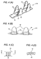
- Fig. 4(A) is a perspective view showing a structure of a connecting terminal 21B in a second embodiment according to the invention
- Fig. 4(B) is a side view
- Fig. 4(C) is a view of the projected part 24 as seen from the above
- Fig. 4(D) is a sectional view as seen in a direction of arrows IV-IV of Fig. 4(C).
- each of the projected parts 24 is provided with unevenness portion 25 arranged in a longitudinal direction of the strip portion 22 on its contact face with respect to the conductive part 42 (refer to Fig. 3).
- Other components of the structure are the same as those of the connecting terminal 21 in the first embodiment as shown in Figs. 1 to 3.
- this connecting terminal 21B since the unevenness portion 25 are formed on the contact face of the projected part 24, a contact area with respect to the conductive part 42 of the flat circuit body 41 (refer to Fig. 3) is enlarged, and favorable conductivity can be obtained as compared with the case where the unevenness portion 25 are not formed. Further, because a surface of the conductive part 42 is press-contacted to the unevenness portion 25, the flat circuit body 40 will not be displaced with respect to the connecting terminal 21 in a longitudinal direction and a favorable state of connection can be maintained.
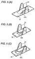
- the projected part 24 is formed by cutting out and raising a portion of the strip portion 22 as described above, besides the projected part 24 of a type wherein both ends of a projected part 24A in the longitudinal direction of the strip portion 22 are connected to the strip portion 22 as shown in Fig. 5(A), a projected part of a cantilever type wherein it is connected to the strip portion 22 at only one end as shown in Fig. 5(B) can be employed.
- an end of a projected part 24C in a widthwise direction of the strip portion 22 may be connected to the strip portion 22 as shown in Fig. 5(C) instead of connecting an end of the projected part 24C in the longitudinal direction of the strip portion 22.
- the claw portions 23 may be in any shape at their tip ends or in any number provided that the conductive part 40 can be clamped between the claw portions 23 and the strip portion 22.
- the left and right claw portions 23 may be arranged in a staggered relation in the longitudinal direction of the strip portion 22 as in a connecting terminal 21C in a third embodiment as shown in Fig. 6.
- a projected part 24D may be manufactured as a separate body from the strip portion 22 in a form of a leaf spring, and assembled between a pair of the claw portions 23 by means of projections 26 and openings 27 as in a connecting terminal 21D in a fourth embodiment as shown in Fig. 7.
- the strip portion 22 and the claw portions 23 themselves may be also formed as separate bodies and then, assembled into an integral body by welding or with a conductive adhesive.
- the projected part 24 may be composed of an elastic material such as rubber and attached to the strip portion 22, because the projected part 24 need not have conductivity necessarily.
- the elastically projected parts are formed on the strip portion. Accordingly, in case where the tip ends of the claw portions have pressed the conductive part with a strong force when the claw portions are passed through the insulating part of the flat circuit body and folded back, the projected parts will be elastically deformed to relieve the force of the claw portions, and prevent the claw portions from being press-contacted to the conductive part with a force above the prescribed value. Therefore, even though the claw portions are not formed with high precision so that the projected length may be within the prescribed value, there will be no fear of damaging the conductive part of the flat circuit body. Thus, the manufacturing cost can be decreased.
- the projected part is formed by partially cutting out the strip portion. Accordingly, the increase of the manufacturing cost can be restrained, as compared with the case wherein the projected part is formed of separate material and then, assembled.
- the projected part is projected from the strip portion in an arcuate shape, and the favorable elasticity can be obtained.
- the projected part is provided with the unevenness portion on its contact face with respect to the conductive part. Accordingly, the area to be in contact with the conductive part can be enlarged as compared with the case where the unevenness portion are not provided, and the favorable conductivity can be obtained when the projected part is made of metal. Since the surface of the conductive part is press-contacted to the unevenness portion, a fear of positional displacement of the flat circuit body with respect to the connecting terminal will be substantially eliminated, whereby the favorable state of connection can be maintained.
Landscapes
- Coupling Device And Connection With Printed Circuit (AREA)
- Multi-Conductor Connections (AREA)
Abstract
Description
Claims (10)
- A connecting terminal adapted to be electrically connected to a conductive part of a flat circuit body, said connecting terminal comprising:a strip portion;at least one claw portion projected from said strip portion in a direction of a thickness of said strip portion;at least one projected part elastically projected from said strip portion in said direction.
- A connector terminal according to claim 1, wherein said projected part is formed by partially cutting out and raising a portion of said strip portion corresponding to said projected part.
- A connector terminal according to claim 1, wherein said projected part is projected from said strip portion in an arcuate shape.
- A connector terminal according to claim 1, wherein said projected part is provided with unevenness part on a contact face of said projected part with respect to said conductive part.
- A connector terminal according to claim 1, wherein said claw portion is penetrated to a insulating part of said flat circuit body in said direction and is folded back toward said strip portion to hold said conductive part between said claw portion and said projected part so that said connecting terminal is electrically connected to said conductive part.
- A connector terminal according to claim 1, wherein a pair of said claw portions is positioned both sides of said projected part.
- A connector terminal according to claim 6, wherein said projected portion is separate from said strip portion and assembled between said pair of said claw portions.
- A connector terminal according to claim 2, wherein said portion is partially cut in parallel with a surface of said claw portion.
- A connector terminal according to claim 2, wherein said portion is partially cut perpendicular to a surface of said claw portion.
- A connector terminal according to claim 1, wherein said projected part has at least one end connected to said strip portion, and a contact face extending from said at least one end and distanced from said strip portion in said direction to define an opening between said contact portion and said strip portion in said direction.
Applications Claiming Priority (2)
| Application Number | Priority Date | Filing Date | Title |
|---|---|---|---|
| JP25329199 | 1999-09-07 | ||
| JP25329199A JP3682841B2 (en) | 1999-09-07 | 1999-09-07 | Flat circuit body connection terminals |
Publications (3)
| Publication Number | Publication Date |
|---|---|
| EP1083633A2 true EP1083633A2 (en) | 2001-03-14 |
| EP1083633A3 EP1083633A3 (en) | 2001-11-21 |
| EP1083633B1 EP1083633B1 (en) | 2003-07-09 |
Family
ID=17249252
Family Applications (1)
| Application Number | Title | Priority Date | Filing Date |
|---|---|---|---|
| EP20000307401 Expired - Lifetime EP1083633B1 (en) | 1999-09-07 | 2000-08-29 | Connecting terminal of a flat circuit body |
Country Status (3)
| Country | Link |
|---|---|
| EP (1) | EP1083633B1 (en) |
| JP (1) | JP3682841B2 (en) |
| DE (1) | DE60003762T2 (en) |
Cited By (2)
| Publication number | Priority date | Publication date | Assignee | Title |
|---|---|---|---|---|
| US7040914B2 (en) | 2000-07-24 | 2006-05-09 | Yazaki Corporation | Electric connecting terminal |
| EP1691452A3 (en) * | 2002-12-18 | 2006-09-27 | Yazaki Corporation | Connecting member for flat circuit member and method of connecting the connecting member and the flat circuit member |
Families Citing this family (2)
| Publication number | Priority date | Publication date | Assignee | Title |
|---|---|---|---|---|
| DE102004061425A1 (en) * | 2004-12-21 | 2006-07-06 | Tyco Electronics Amp Gmbh | Electrical connector for attachment of electrical conductor to flexible flat cable, has base section to which conductive strip of flat cable is electrically connected elastically over at least one contact area |
| CN212161961U (en) * | 2020-05-26 | 2020-12-15 | 宁德时代新能源科技股份有限公司 | Signal transmission terminal, sampling device, battery module and device |
Family Cites Families (4)
| Publication number | Priority date | Publication date | Assignee | Title |
|---|---|---|---|---|
| GB1466086A (en) * | 1974-07-18 | 1977-03-02 | Cannon Electric Great Britain | Electrical terminations |
| JPH0754720B2 (en) * | 1987-04-10 | 1995-06-07 | Electrical connection terminals for flexible printed circuit boards | |
| JPH0747810Y2 (en) * | 1990-05-09 | 1995-11-01 | 住友電装株式会社 | Electrical connector for flexible flat conductor cable |
| JPH0569858U (en) * | 1992-02-25 | 1993-09-21 | 矢崎総業株式会社 | Pressure contact terminal |
-
1999
- 1999-09-07 JP JP25329199A patent/JP3682841B2/en not_active Expired - Fee Related
-
2000
- 2000-08-29 EP EP20000307401 patent/EP1083633B1/en not_active Expired - Lifetime
- 2000-08-29 DE DE2000603762 patent/DE60003762T2/en not_active Expired - Lifetime
Cited By (3)
| Publication number | Priority date | Publication date | Assignee | Title |
|---|---|---|---|---|
| US7040914B2 (en) | 2000-07-24 | 2006-05-09 | Yazaki Corporation | Electric connecting terminal |
| DE10134944B4 (en) * | 2000-07-24 | 2006-05-18 | Yazaki Corp. | Electrical connection terminal |
| EP1691452A3 (en) * | 2002-12-18 | 2006-09-27 | Yazaki Corporation | Connecting member for flat circuit member and method of connecting the connecting member and the flat circuit member |
Also Published As
| Publication number | Publication date |
|---|---|
| DE60003762T2 (en) | 2004-02-05 |
| JP3682841B2 (en) | 2005-08-17 |
| JP2001076781A (en) | 2001-03-23 |
| EP1083633A3 (en) | 2001-11-21 |
| DE60003762D1 (en) | 2003-08-14 |
| EP1083633B1 (en) | 2003-07-09 |
Similar Documents
| Publication | Publication Date | Title |
|---|---|---|
| US6312263B1 (en) | Board-to-board connector capable of readily electrically connecting two parallel boards to each other | |
| EP1327997B1 (en) | Elastic sheet structure having an improved electrical continuity function, and printed circuit board structure | |
| US9466907B2 (en) | Connector | |
| EP0651466A2 (en) | Area and edge array electrical connectors | |
| US6017222A (en) | Electrical connector assembly for connecting flexible connecting strips of a film circuitry and a main circuit board | |
| US6565376B2 (en) | Flat cable terminal | |
| EP1100166B1 (en) | Electrical connector | |
| EP1349240B1 (en) | Connector in which movement of contact portion of contact is guided by insulator | |
| EP1603197B1 (en) | Connector which can be reduced in warpage | |
| EP1083633B1 (en) | Connecting terminal of a flat circuit body | |
| EP0478364B1 (en) | Connector device | |
| US6638078B2 (en) | Connector suitable for connecting a pair of circuit boards arranged in parallel | |
| US7040914B2 (en) | Electric connecting terminal | |
| JP4101446B2 (en) | Electrical connection terminal | |
| US5505626A (en) | Electrical connector with tension adjusting means | |
| US7201606B2 (en) | Wire connection structure and connector | |
| US12548926B2 (en) | Electrical connection terminal and battery pack signal acquisition device | |
| JP3237834B2 (en) | Flexible circuit board | |
| JPH04133365U (en) | elastomer connector | |
| US7544098B2 (en) | Connector having a stopper mechanism defining a movable range of a housing receiving a connection object | |
| US5860813A (en) | Elastomeric connector with control of loose circuitry | |
| WO2020171204A1 (en) | Conversion connector and substrate connection structure | |
| JP4043698B2 (en) | Wire holding structure | |
| CN219643144U (en) | Terminal, electric connector, wire harness and vehicle | |
| WO2004109862A1 (en) | Wire connection structure and connector |
Legal Events
| Date | Code | Title | Description |
|---|---|---|---|
| PUAI | Public reference made under article 153(3) epc to a published international application that has entered the european phase |
Free format text: ORIGINAL CODE: 0009012 |
|
| AK | Designated contracting states |
Kind code of ref document: A2 Designated state(s): AT BE CH CY DE DK ES FI FR GB GR IE IT LI LU MC NL PT SE Kind code of ref document: A2 Designated state(s): DE FR GB IT |
|
| AX | Request for extension of the european patent |
Free format text: AL;LT;LV;MK;RO;SI |
|
| PUAL | Search report despatched |
Free format text: ORIGINAL CODE: 0009013 |
|
| AK | Designated contracting states |
Kind code of ref document: A3 Designated state(s): AT BE CH CY DE DK ES FI FR GB GR IE IT LI LU MC NL PT SE |
|
| AX | Request for extension of the european patent |
Free format text: AL;LT;LV;MK;RO;SI |
|
| 17P | Request for examination filed |
Effective date: 20020425 |
|
| 17Q | First examination report despatched |
Effective date: 20020619 |
|
| AKX | Designation fees paid |
Free format text: DE FR GB IT |
|
| GRAH | Despatch of communication of intention to grant a patent |
Free format text: ORIGINAL CODE: EPIDOS IGRA |
|
| RTI1 | Title (correction) |
Free format text: CONNECTING TERMINAL OF A FLAT CIRCUIT BODY |
|
| GRAH | Despatch of communication of intention to grant a patent |
Free format text: ORIGINAL CODE: EPIDOS IGRA |
|
| GRAA | (expected) grant |
Free format text: ORIGINAL CODE: 0009210 |
|
| AK | Designated contracting states |
Designated state(s): DE FR GB IT |
|
| REG | Reference to a national code |
Ref country code: GB Ref legal event code: FG4D |
|
| REF | Corresponds to: |
Ref document number: 60003762 Country of ref document: DE Date of ref document: 20030814 Kind code of ref document: P |
|
| ET | Fr: translation filed | ||
| PLBE | No opposition filed within time limit |
Free format text: ORIGINAL CODE: 0009261 |
|
| STAA | Information on the status of an ep patent application or granted ep patent |
Free format text: STATUS: NO OPPOSITION FILED WITHIN TIME LIMIT |
|
| 26N | No opposition filed |
Effective date: 20040414 |
|
| PGFP | Annual fee paid to national office [announced via postgrant information from national office to epo] |
Ref country code: GB Payment date: 20130828 Year of fee payment: 14 Ref country code: FR Payment date: 20130808 Year of fee payment: 14 |
|
| PGFP | Annual fee paid to national office [announced via postgrant information from national office to epo] |
Ref country code: IT Payment date: 20130819 Year of fee payment: 14 |
|
| GBPC | Gb: european patent ceased through non-payment of renewal fee |
Effective date: 20140829 |
|
| PG25 | Lapsed in a contracting state [announced via postgrant information from national office to epo] |
Ref country code: IT Free format text: LAPSE BECAUSE OF NON-PAYMENT OF DUE FEES Effective date: 20140829 |
|
| REG | Reference to a national code |
Ref country code: FR Ref legal event code: ST Effective date: 20150430 |
|
| PG25 | Lapsed in a contracting state [announced via postgrant information from national office to epo] |
Ref country code: GB Free format text: LAPSE BECAUSE OF NON-PAYMENT OF DUE FEES Effective date: 20140829 |
|
| PG25 | Lapsed in a contracting state [announced via postgrant information from national office to epo] |
Ref country code: FR Free format text: LAPSE BECAUSE OF NON-PAYMENT OF DUE FEES Effective date: 20140901 |
|
| PGFP | Annual fee paid to national office [announced via postgrant information from national office to epo] |
Ref country code: DE Payment date: 20150825 Year of fee payment: 16 |
|
| REG | Reference to a national code |
Ref country code: DE Ref legal event code: R119 Ref document number: 60003762 Country of ref document: DE |
|
| PG25 | Lapsed in a contracting state [announced via postgrant information from national office to epo] |
Ref country code: DE Free format text: LAPSE BECAUSE OF NON-PAYMENT OF DUE FEES Effective date: 20170301 |