EP1083499B1 - Method for thermal fluid analysis and thermal stress analysis of fluid machine - Google Patents
Method for thermal fluid analysis and thermal stress analysis of fluid machine Download PDFInfo
- Publication number
- EP1083499B1 EP1083499B1 EP00105096A EP00105096A EP1083499B1 EP 1083499 B1 EP1083499 B1 EP 1083499B1 EP 00105096 A EP00105096 A EP 00105096A EP 00105096 A EP00105096 A EP 00105096A EP 1083499 B1 EP1083499 B1 EP 1083499B1
- Authority
- EP
- European Patent Office
- Prior art keywords
- analysis
- mesh
- fluid
- thermal
- fluid analysis
- Prior art date
- Legal status (The legal status is an assumption and is not a legal conclusion. Google has not performed a legal analysis and makes no representation as to the accuracy of the status listed.)
- Expired - Lifetime
Links
Images



Classifications
-
- G—PHYSICS
- G06—COMPUTING OR CALCULATING; COUNTING
- G06F—ELECTRIC DIGITAL DATA PROCESSING
- G06F17/00—Digital computing or data processing equipment or methods, specially adapted for specific functions
- G06F17/10—Complex mathematical operations
- G06F17/16—Matrix or vector computation, e.g. matrix-matrix or matrix-vector multiplication, matrix factorization
-
- G—PHYSICS
- G06—COMPUTING OR CALCULATING; COUNTING
- G06F—ELECTRIC DIGITAL DATA PROCESSING
- G06F30/00—Computer-aided design [CAD]
- G06F30/20—Design optimisation, verification or simulation
- G06F30/23—Design optimisation, verification or simulation using finite element methods [FEM] or finite difference methods [FDM]
-
- G—PHYSICS
- G06—COMPUTING OR CALCULATING; COUNTING
- G06F—ELECTRIC DIGITAL DATA PROCESSING
- G06F2111/00—Details relating to CAD techniques
- G06F2111/10—Numerical modelling
Definitions
- the present invention relates to a method for analyzing, in a short time with a high precision, both of thermal fluid analysis and thermal stress analysis of fluid machines.
- a turbocharger or a turbo-compressor is a fluid machine which has a complicated three-dimensional shape including a large number of free form surfaces and including a large number of machine elements. It is also exposed to a severe environment in which high-speed rotation is required at a high temperature. Therefore, both of the analysis of a thermal fluid flowing through the fluid machine and the analysis of a structure constituting the turbocharger are indispensable to the research and development of the turbocharger or the like.
- Fig. 1 is a flowchart schematically showing a conventional analysis method.
- the conventional analysis method comprises first obtaining a temperature distribution from the thermal fluid analysis, and then performing the thermal conduction analysis and the thermal stress analysis of a solid section.
- each range of close values is formed into a large group, a representative value is set, and the value is manually mapped to the other side (for the structure analysis). Consequently, in this analysis method, there are problems that the analysis requires much time, and that calculation precision is deteriorated.
- interface parts connecting analysis steps need to be manually operated, and as a result, it takes a long period of about several months (e.g., three months) to analyze one model.
- an object of the present invention is to provide an analysis method for thermal fluid analysis and thermal stress analysis of a turbocharger requiring both of the thermal fluid analysis and the thermal stress analysis can be performed in a short time with a high precision by remarkably reducing or eliminating interface parts dependent on manual operations.
- the fluid analysis mesh and structure analysis mesh are automatically prepared in parallel, the mesh production by the manual operation can be eliminated. Moreover, since the results of the thermal fluid analysis based on the fluid analysis mesh are subjected to the automatic data mapping to the structure analysis mesh, the conventional manual mapping for the structure analysis can be eliminated. Therefore, the interface parts by the manual operations can substantially be eliminated so that the fluid machine analysis can be performed in a short time with a high precision.
- the automatic data mapping comprises performing interpolation between the fluid analysis mesh and the structure analysis mesh different from each other in the number meshes based on the data obtained in the thermal fluid analysis and preparing the data of the heat conductivity and wall surface temperature for the structure analysis mesh.
- the heat conductivity and wall surface temperature obtained from the thermal fluid analysis can automatically be mapped to the structure analysis mesh.
- the fluid analysis mesh and structure analysis mesh are prepared by automatic tetra-mesh division for division to tetrahedron cells.
- the automatic tetra-mesh division may be dependent on an automatic lattice generation algorithm of any one of an oct-tree technique, a Delaunay triangulation technique, and an advancing-front technique.
- the automatic division which cannot be realized in the conventional division to hexahedron cells can be realized by the division to the tetrahedron cells.
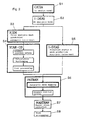
- Fig. 2 is a flowchart of an analysis method for thermal fluid analysis and thermal stress analysis of a turbocharger according to the present invention.
- the analysis method since the analysis method is incorporated in a development process on the basis of three-dimensional model data, the method flows on the assumption that a three-dimensional design model is already prepared in the development process. Moreover, the processing is automated using interface tools which connect several processings.
- step S1 the analysis method of the present invention is roughly classified into eight steps S1 to S8.
- step S2 the 3D design model is prepared, for example, using CATIA.
- step S2 a 3D analysis model is prepared, for example, using I-DEAS.
- step S3 a fluid analysis mesh is automatically prepared as a tetra-mesh, for example, using ICEM.
- Step S4 is constituted of boundary condition setting, calculating and post processing, and, for example, STAR-CD is used to perform thermal fluid analysis.
- step S5 a structure analysis mesh is automatically prepared as the tetra-mesh, for example, using I-DEAS.
- step S6 for example, PATRAN is used to perform automatic data mapping, and subsequently boundary conditions are set.
- step S7 for example, NASTRAN is used to calculate thermal stress.
- step S8 the post processing is performed.
- CATIA CATIA
- I-DEAS I-DEAS
- ICEM ICEM
- STAR-CD PATRAN
- NASTRAN NASTRAN
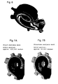
- Figs. 7A, 7B show the temperature data on the fluid analysis mesh before the mapping, and the temperature data on the structure analysis mesh after the mapping.
- Fig. 7A shows the temperature data on the fluid analysis mesh (about 420,000 meshes)
- Fig. 7B shows the temperature data on the structure analysis mesh (about 82,000 meshes).
- the automatic data mapping is used to perform the interpolation between the meshes different in number while the data is exchanged, so that a sufficient precision can be obtained. In this example, the mapping was completed in about seven hours. Since the conventional manual mapping requires about three months, as compared with this, great effects can be obtained in both the remarkable time reduction and the enhancement of precision.
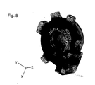
- Fig. 8 shows the example of finally obtained thermal stress analysis result. Additionally, the concentration in the drawing results from the division of the thermal stress distribution by color, but the detailed description is omitted here.
- the fluid analysis mesh and structure analysis mesh are automatically prepared in parallel, the mesh production by manual operation can be eliminated. Moreover, the thermal fluid analysis result based on the fluid analysis mesh is subjected to the automatic data mapping for the structure analysis mesh, the conventional manual mapping to the structure analysis can be eliminated. Therefore, the analysis of the fluid machine can be performed in a short time with a high precision by substantially eliminating the interface part by the manual operation.
- the interpolation is performed between the fluid analysis mesh and the structure analysis mesh different in the number of meshes based on the data obtained by the thermal fluid analysis to prepare the data of the heat conductivity and wall surface temperature adapted for the structure analysis mesh, so that the heat conductivity and wall surface temperature obtained from the thermal fluid analysis can automatically be mapped to the structure analysis mesh.
- the automatic division which has not been realized in the conventional division to the hexahedron cells can be realized by the division to the tetrahedron cells.
- the analysis method for the thermal fluid analysis and the thermal stress analysis of a turbocharger according to the present invention provides an excellent effect that the analysis of the turbocharger requiring both the thermal fluid analysis and the thermal stress analysis can be performed in a short time with a high precision by remarkably reducing or eliminating the interface parts by the manual operations.
Landscapes
- Engineering & Computer Science (AREA)
- Physics & Mathematics (AREA)
- General Physics & Mathematics (AREA)
- Theoretical Computer Science (AREA)
- Mathematical Physics (AREA)
- Mathematical Analysis (AREA)
- Mathematical Optimization (AREA)
- Data Mining & Analysis (AREA)
- Computational Mathematics (AREA)
- General Engineering & Computer Science (AREA)
- Pure & Applied Mathematics (AREA)
- Computing Systems (AREA)
- Computer Hardware Design (AREA)
- Evolutionary Computation (AREA)
- Algebra (AREA)
- Geometry (AREA)
- Databases & Information Systems (AREA)
- Software Systems (AREA)
- Investigating Or Analyzing Materials Using Thermal Means (AREA)
- Supercharger (AREA)
- Structures Of Non-Positive Displacement Pumps (AREA)
Description
- The present invention relates to a method for analyzing, in a short time with a high precision, both of thermal fluid analysis and thermal stress analysis of fluid machines.
- A turbocharger or a turbo-compressor is a fluid machine which has a complicated three-dimensional shape including a large number of free form surfaces and including a large number of machine elements. It is also exposed to a severe environment in which high-speed rotation is required at a high temperature. Therefore, both of the analysis of a thermal fluid flowing through the fluid machine and the analysis of a structure constituting the turbocharger are indispensable to the research and development of the turbocharger or the like.
-
Fig. 1 is a flowchart schematically showing a conventional analysis method. As shown inFig. 1 , the conventional analysis method comprises first obtaining a temperature distribution from the thermal fluid analysis, and then performing the thermal conduction analysis and the thermal stress analysis of a solid section. - In the conventional analysis method shown in
Fig. 1 , since article production (turbocharger manufacture) proceeds based on two-dimensional drawing, the analysis itself is carried out independently of this manufacture process. Therefore, the conventional analysis method has a problem that much time is required for analysis in steps A, B, C, D shown by bold-line frames inFig. 1 . This problem will further be described in detail hereinafter. - (1) Preparation of Three-dimensional Model (Step A)
Since the conventional development is performed in two dimensions, a three-dimensional model for analysis is prepared after the completion of the drawing. Therefore, in the modeling of the part which cannot be represented by the two-dimensional drawing, designers and model makers have to exchange communications, and it sometimes takes a great deal of time to prepare the model. - (2) Mesh production (Steps B, C)
Since a mesh to be prepared for fluid analysis is finer than that for structure analysis, and is usually a hexahedron, the mesh needs to be manually prepared, which requires time and labor. Moreover, in the preparation of the mesh for structure analysis, coarse division may be performed, but the matching with the mesh for fluid analysis needs to be considered, and the mesh needs to also be manually prepared. - (3) Mapping of Temperature Data (Step D)
- In the conventional analysis flow, since the thermal fluid analysis and the Thermal transfer analysis are independent of each other, calculation has to be performed by placing insulation or a certain tentative value between solid and fluid. Moreover, a heat conductivity and wall surface temperature obtained from the thermal fluid analysis need to be manually mapped to the mesh for structure analysis (an operation of setting the heat conductivity and wall surface temperature of each part). Furthermore, in this mapping, since the number of meshes differs largely between the fluid analysis and the structure analysis, and further the number is enormous. Therefore it is very difficult to accurately perform the manual mapping. For example, in the example described later, the number of meshes for the fluid analysis is about 690,000, and the number of meshes for the structure analysis is about 80,000.
- Therefore, for the data of the heat conductivity and wall surface temperature obtained from the thermal fluid analysis, each range of close values is formed into a large group, a representative value is set, and the value is manually mapped to the other side (for the structure analysis). Consequently, in this analysis method, there are problems that the analysis requires much time, and that calculation precision is deteriorated.
- As described above, in the conventional analysis method, interface parts connecting analysis steps need to be manually operated, and as a result, it takes a long period of about several months (e.g., three months) to analyze one model.
- A method for thermal fluid analysis and thermal stress analysis of a fluid machine is disclosed on" Recent Advances in Thermal/Flow Simulation:Integrating Thermal Analysis into the Mechanical Design Process" Free et al 7-9.02.1995
- The present invention has been developed to solve these problems. Specifically, an object of the present invention is to provide an analysis method for thermal fluid analysis and thermal stress analysis of a turbocharger requiring both of the thermal fluid analysis and the thermal stress analysis can be performed in a short time with a high precision by remarkably reducing or eliminating interface parts dependent on manual operations.
- According to the present invention, there is provided an analysis method for thermal fluid analysis and thermal stress analysis of a turbocharger as defined in claim 1.
- According to the above-described method of the present invention, since the fluid analysis mesh and structure analysis mesh are automatically prepared in parallel, the mesh production by the manual operation can be eliminated. Moreover, since the results of the thermal fluid analysis based on the fluid analysis mesh are subjected to the automatic data mapping to the structure analysis mesh, the conventional manual mapping for the structure analysis can be eliminated. Therefore, the interface parts by the manual operations can substantially be eliminated so that the fluid machine analysis can be performed in a short time with a high precision.
- According to a preferred mode for carrying out the present invention, the automatic data mapping comprises performing interpolation between the fluid analysis mesh and the structure analysis mesh different from each other in the number meshes based on the data obtained in the thermal fluid analysis and preparing the data of the heat conductivity and wall surface temperature for the structure analysis mesh.
- According to the method, the heat conductivity and wall surface temperature obtained from the thermal fluid analysis can automatically be mapped to the structure analysis mesh.
- Moreover, the fluid analysis mesh and structure analysis mesh are prepared by automatic tetra-mesh division for division to tetrahedron cells. Furthermore, the automatic tetra-mesh division may be dependent on an automatic lattice generation algorithm of any one of an oct-tree technique, a Delaunay triangulation technique, and an advancing-front technique.
- According to this method, the automatic division which cannot be realized in the conventional division to hexahedron cells can be realized by the division to the tetrahedron cells.
- Other objects and advantageous characteristics of the present invention will be apparent from the following description with reference to the accompanying drawings.
-
-
Fig. 1 is a flowchart of a conventional analysis method for thermal fluid analysis and thermal stress analysis. -
Fig. 2 is a flowchart of an analysis method for thermal fluid analysis and thermal stress analysis of a fluid machine according to the present invention. -
Fig. 3 is a shape model diagram of an analysis model. -
Fig. 4 is a diagram showing the example of a fluid analysis mesh. -
Fig. 5 is a diagram showing the example of a structure analysis mesh. -
Fig. 6 shows the example of a temperature distribution calculation result. -
Fig. 7 is a diagram showing the automatic mapping example of temperature data. -
Fig. 8 is a diagram showing a thermal stress calculation result. - Preferred embodiments of the present invention will be described hereinafter with reference to the drawings.
-
Fig. 2 is a flowchart of an analysis method for thermal fluid analysis and thermal stress analysis of a turbocharger according to the present invention. In the present invention, since the analysis method is incorporated in a development process on the basis of three-dimensional model data, the method flows on the assumption that a three-dimensional design model is already prepared in the development process. Moreover, the processing is automated using interface tools which connect several processings. - As shown in
Fig. 2 , the analysis method of the present invention is roughly classified into eight steps S1 to S8. In step S1, the 3D design model is prepared, for example, using CATIA. In step S2, a 3D analysis model is prepared, for example, using I-DEAS. In step S3, a fluid analysis mesh is automatically prepared as a tetra-mesh, for example, using ICEM. Step S4 is constituted of boundary condition setting, calculating and post processing, and, for example, STAR-CD is used to perform thermal fluid analysis. In step S5, a structure analysis mesh is automatically prepared as the tetra-mesh, for example, using I-DEAS. In step S6, for example, PATRAN is used to perform automatic data mapping, and subsequently boundary conditions are set. In step S7, for example, NASTRAN is used to calculate thermal stress. In step S8, the post processing is performed. - Additionally, the above-described CATIA, I-DEAS, ICEM, STAR-CD, PATRAN and NASTRAN are existing finite element process general-purpose software. Comparison with the conventional analysis method will be described hereinafter.
- (1) Three-dimensional Model Preparation (steps S1, S2)
In the development process mainly on the basis of the three-dimensional model data, the designers themselves prepare the three-dimensional model in their design operations. Therefore, as compared with the conventional method in which the model is newly prepared from the two-dimensional drawing, in the method of the present invention, remarkable speedup is enabled. Moreover, the mismatching of the model because of the misunderstanding of the designers and analyzers can be avoided.Fig. 3 shows the example of a model forming a basis of analysis. - (2) Mesh production (Steps S3, S5)
In the method of the present invention, since both the fluid analysis and the structure analysis use an automatic tetra-mesh, the operation time can remarkably be shortened. Specifically, the fluid analysis mesh and structure analysis mesh are prepared by automatic tetra-mesh division for the division to tetrahedron cells. This automatic tetra-mesh division may be dependent on the automatic lattice generation algorithm of any one of the oct-tree technique, the Delaunay triangulation technique, and the advancing-front technique. In the conventional method the division to the hexahedron cells is manually performed, but the mesh production can automatically be performed by the division to the tetrahedron cells.Fig 4 shows the example of the fluid analysis mesh, andFig. 5 shows the example of the structure analysis mesh. - (3) Mapping of Temperature Data (Steps S4, S6)
Fig. 6 shows temperature distribution data of a solid section as a result of thermal fluid analysis. Additionally, the gradation inFig. 6 is obtained by dividing the temperature distribution by color, but detailed description is omitted here. In this example a cooling water passage is disposed around a high-temperature gas passage, and heat comes in and out through the solid section. Therefore, the Thermal transfer of the solid section was also calculated on the thermal fluid analysis side. The result was mapped to the structure analysis mesh from the fluid analysis mesh by automatic data mapping through a structure analyzing preprocessor. -
Figs. 7A, 7B show the temperature data on the fluid analysis mesh before the mapping, and the temperature data on the structure analysis mesh after the mapping.Fig. 7A shows the temperature data on the fluid analysis mesh (about 420,000 meshes), andFig. 7B shows the temperature data on the structure analysis mesh (about 82,000 meshes). The automatic data mapping is used to perform the interpolation between the meshes different in number while the data is exchanged, so that a sufficient precision can be obtained. In this example, the mapping was completed in about seven hours. Since the conventional manual mapping requires about three months, as compared with this, great effects can be obtained in both the remarkable time reduction and the enhancement of precision. -
Fig. 8 shows the example of finally obtained thermal stress analysis result. Additionally, the concentration in the drawing results from the division of the thermal stress distribution by color, but the detailed description is omitted here. - As described above, according to the method of the present invention, since the fluid analysis mesh and structure analysis mesh are automatically prepared in parallel, the mesh production by manual operation can be eliminated. Moreover, the thermal fluid analysis result based on the fluid analysis mesh is subjected to the automatic data mapping for the structure analysis mesh, the conventional manual mapping to the structure analysis can be eliminated. Therefore, the analysis of the fluid machine can be performed in a short time with a high precision by substantially eliminating the interface part by the manual operation.
- Moreover, in the automatic data mapping, the interpolation is performed between the fluid analysis mesh and the structure analysis mesh different in the number of meshes based on the data obtained by the thermal fluid analysis to prepare the data of the heat conductivity and wall surface temperature adapted for the structure analysis mesh, so that the heat conductivity and wall surface temperature obtained from the thermal fluid analysis can automatically be mapped to the structure analysis mesh.
- Furthermore, for the preparation of the fluid analysis mesh and structure analysis mesh, according to the method of the automatic tetra-mesh division for the division to the tetrahedron cells, the automatic division which has not been realized in the conventional division to the hexahedron cells can be realized by the division to the tetrahedron cells.
- As described above, the analysis method for the thermal fluid analysis and the thermal stress analysis of a turbocharger according to the present invention provides an excellent effect that the analysis of the turbocharger requiring both the thermal fluid analysis and the thermal stress analysis can be performed in a short time with a high precision by remarkably reducing or eliminating the interface parts by the manual operations.
Claims (1)
- An analysis method for thermal fluid analysis and thermal stress analysis of a turbocharger which comprises the steps of
automatically preparing a fluid analysis mesh (S3) and a structure analysis mesh (S5) different from each other in the number of meshes from a three-dimensional model (S1, S2) of the turbocharger;
performing the thermal fluid analysis(S4) based on the fluid analysis mesh;
subjecting the results obtained by the thermal fluid analysis to automatic data mapping (S6) in compliance with the structure analysis mesh; and
then calculating thermal stress (S7) based on the structure analysis mesh,
wherein
preparing the fluid analysis mesh (S3) and the structure analysis mesh (S5) is performed in parallel,
the automatic data mapping (S6) is performed by interpolating between the fluid analysis mesh and the structure analysis mesh,
the method further comprises the step of simultaneously preparing data of heat conductivity and wall surface temperature adapted for the structure analysis mesh,
said fluid analysis mesh and said structure analysis mesh are prepared by automatic tetra-mesh division for division to tetrahedron cells, and
said automatic tetra-mesh division is performed by an automatic lattice generation algorithm of any one of an oct-tree technique, a Delaunay triangulation technique and an advancing-front technique.
Applications Claiming Priority (2)
| Application Number | Priority Date | Filing Date | Title |
|---|---|---|---|
| JP25767199A JP2001082391A (en) | 1999-09-10 | 1999-09-10 | Thermal fluid analysis and thermal stress analysis method for fluid machinery |
| JP25767199 | 1999-09-10 |
Publications (3)
| Publication Number | Publication Date |
|---|---|
| EP1083499A2 EP1083499A2 (en) | 2001-03-14 |
| EP1083499A3 EP1083499A3 (en) | 2003-08-20 |
| EP1083499B1 true EP1083499B1 (en) | 2009-05-13 |
Family
ID=17309498
Family Applications (1)
| Application Number | Title | Priority Date | Filing Date |
|---|---|---|---|
| EP00105096A Expired - Lifetime EP1083499B1 (en) | 1999-09-10 | 2000-03-10 | Method for thermal fluid analysis and thermal stress analysis of fluid machine |
Country Status (4)
| Country | Link |
|---|---|
| EP (1) | EP1083499B1 (en) |
| JP (1) | JP2001082391A (en) |
| KR (1) | KR100662996B1 (en) |
| DE (1) | DE60042190D1 (en) |
Families Citing this family (2)
| Publication number | Priority date | Publication date | Assignee | Title |
|---|---|---|---|---|
| JP2010186395A (en) * | 2009-02-13 | 2010-08-26 | Hitachi Chem Co Ltd | Method and system for analyzing particle deformation for resin material containing particle |
| JP5210284B2 (en) * | 2009-10-28 | 2013-06-12 | 株式会社日立製作所 | Thermal fluid pressure data evaluation system |
Family Cites Families (6)
| Publication number | Priority date | Publication date | Assignee | Title |
|---|---|---|---|---|
| JPS60226603A (en) * | 1984-04-24 | 1985-11-11 | バブコツク日立株式会社 | Device for predicting thermal stress of boiler |
| US5154795A (en) * | 1989-06-12 | 1992-10-13 | Mitsubishi Kasei Polytec Company | System for setting analysis condition for a thermal analysis of a fluid inside an apparatus |
| US5202843A (en) * | 1990-04-25 | 1993-04-13 | Oki Electric Industry Co., Ltd. | CAE system for automatic heat analysis of electronic equipment |
| US5550750A (en) * | 1993-05-28 | 1996-08-27 | Mentor Graphics Corporation | Method and system for integrating component analysis with multiple component placement |
| US5644687A (en) * | 1994-12-29 | 1997-07-01 | International Business Machines Corporation | Methods and system for thermal analysis of electronic packages |
| US5729670A (en) * | 1996-01-16 | 1998-03-17 | Ford Global Technologies, Inc. | Method for producing a mesh of quadrilateral/hexahedral elements for a body to be analyzed using finite element analysis |
-
1999
- 1999-09-10 JP JP25767199A patent/JP2001082391A/en active Pending
-
2000
- 2000-03-09 KR KR1020000011768A patent/KR100662996B1/en not_active Expired - Fee Related
- 2000-03-10 EP EP00105096A patent/EP1083499B1/en not_active Expired - Lifetime
- 2000-03-10 DE DE60042190T patent/DE60042190D1/en not_active Expired - Lifetime
Non-Patent Citations (1)
| Title |
|---|
| "Current Mechanical Design and Analysis Processes at LaRC", INTERNET ARTICLE, INTERNET, Retrieved from the Internet <URL:http://web.archive.org/web/19990203230457/http://amsd-www.larc.nasa.gov/amsd/refs/des_analysis.html> [retrieved on 20041021] * |
Also Published As
| Publication number | Publication date |
|---|---|
| JP2001082391A (en) | 2001-03-27 |
| KR20010029586A (en) | 2001-04-06 |
| DE60042190D1 (en) | 2009-06-25 |
| EP1083499A3 (en) | 2003-08-20 |
| EP1083499A2 (en) | 2001-03-14 |
| KR100662996B1 (en) | 2006-12-28 |
Similar Documents
| Publication | Publication Date | Title |
|---|---|---|
| CN111968004A (en) | High-precision product assembling and adjusting integrated system based on digital twins | |
| Jiang et al. | Frame field singularity correctionfor automatic hexahedralization | |
| Cheng | Automatic adaptive remeshing for finite element simulation of forming processes | |
| CN106373184B (en) | A kind of 3 D-printing model puts required amount of support Method of fast estimating | |
| CN116502358A (en) | A Stress Prediction System and Method for Precision Castings of Turbine Blades Based on Digital Twins | |
| CN115795594B (en) | BIM modeling method applied to gate station special-shaped curved surface water inlet and outlet channel design | |
| CN116664776A (en) | Three-dimensional visual editing system based on digital twin | |
| CN120672986B (en) | A Method and System for Fitting 3D Terrain Entities with Smooth Non-uniform Rational B-Splines | |
| EP1321867A1 (en) | Method of designing product using 3-dimensional model | |
| Zhang et al. | Cavity optimization for investment casting die of turbine blade based on reverse engineering | |
| CN118070421A (en) | An optimization and evaluation method for the design of detection and positioning benchmarks for automobile surface-covered stamping parts | |
| CN109002581A (en) | High temperature alloy non-standard fastener Plastic Forming Reverse Design based on emulation | |
| EP1083499A2 (en) | Method for thermal fluid analysis and thermal stress analysis of fluid machine | |
| JP2004272820A (en) | Method and system for reverse engineering and re-engineering parts | |
| CN121052046A (en) | A method for material removal simulation and workpiece deformation prediction based on extended finite element model and its application | |
| CN115186326A (en) | Landscape modeling curved surface gradient analysis and control method based on BIM | |
| CN107977522A (en) | A kind of CAE modeling methods of automation component connection | |
| CN114462131B (en) | A complex three-dimensional geological body reverse modeling method suitable for finite element numerical simulation | |
| CN100468413C (en) | Method and system for reverse redesigning components | |
| CN117390926A (en) | A temperature field and stress field simulation calculation method for metal laser additive and subtractive hybrid manufacturing | |
| CN117841311A (en) | Application of high-efficiency cooling conformal waterway based on simulation optimization | |
| Hariya et al. | Automatic hexahedral mesh generation with feature line extraction | |
| CN113468697B (en) | Forward design method for steel frame structure of photovoltaic plate | |
| CN114036822A (en) | Rapid thermal model construction method based on neural network | |
| CN113191061B (en) | Finite element mesh transformation method based on curved surface feature recognition |
Legal Events
| Date | Code | Title | Description |
|---|---|---|---|
| PUAI | Public reference made under article 153(3) epc to a published international application that has entered the european phase |
Free format text: ORIGINAL CODE: 0009012 |
|
| AK | Designated contracting states |
Kind code of ref document: A2 Designated state(s): AT BE CH CY DE DK ES FI FR GB GR IE IT LI LU MC NL PT SE |
|
| AX | Request for extension of the european patent |
Free format text: AL;LT;LV;MK;RO;SI |
|
| 17P | Request for examination filed |
Effective date: 20010808 |
|
| PUAL | Search report despatched |
Free format text: ORIGINAL CODE: 0009013 |
|
| AK | Designated contracting states |
Designated state(s): AT BE CH CY DE DK ES FI FR GB GR IE IT LI LU MC NL PT SE |
|
| AX | Request for extension of the european patent |
Extension state: AL LT LV MK RO SI |
|
| 17Q | First examination report despatched |
Effective date: 20031230 |
|
| AKX | Designation fees paid |
Designated state(s): DE FR GB IT |
|
| 17Q | First examination report despatched |
Effective date: 20031230 |
|
| RAP1 | Party data changed (applicant data changed or rights of an application transferred) |
Owner name: IHI CORPORATION |
|
| GRAP | Despatch of communication of intention to grant a patent |
Free format text: ORIGINAL CODE: EPIDOSNIGR1 |
|
| GRAS | Grant fee paid |
Free format text: ORIGINAL CODE: EPIDOSNIGR3 |
|
| GRAA | (expected) grant |
Free format text: ORIGINAL CODE: 0009210 |
|
| AK | Designated contracting states |
Kind code of ref document: B1 Designated state(s): DE FR GB IT |
|
| REG | Reference to a national code |
Ref country code: GB Ref legal event code: FG4D |
|
| REF | Corresponds to: |
Ref document number: 60042190 Country of ref document: DE Date of ref document: 20090625 Kind code of ref document: P |
|
| PLBE | No opposition filed within time limit |
Free format text: ORIGINAL CODE: 0009261 |
|
| STAA | Information on the status of an ep patent application or granted ep patent |
Free format text: STATUS: NO OPPOSITION FILED WITHIN TIME LIMIT |
|
| 26N | No opposition filed |
Effective date: 20100216 |
|
| PGFP | Annual fee paid to national office [announced via postgrant information from national office to epo] |
Ref country code: FR Payment date: 20140311 Year of fee payment: 15 Ref country code: IT Payment date: 20140307 Year of fee payment: 15 |
|
| PGFP | Annual fee paid to national office [announced via postgrant information from national office to epo] |
Ref country code: GB Payment date: 20140305 Year of fee payment: 15 |
|
| PGFP | Annual fee paid to national office [announced via postgrant information from national office to epo] |
Ref country code: DE Payment date: 20140417 Year of fee payment: 15 |
|
| REG | Reference to a national code |
Ref country code: DE Ref legal event code: R119 Ref document number: 60042190 Country of ref document: DE |
|
| GBPC | Gb: european patent ceased through non-payment of renewal fee |
Effective date: 20150310 |
|
| PG25 | Lapsed in a contracting state [announced via postgrant information from national office to epo] |
Ref country code: IT Free format text: LAPSE BECAUSE OF NON-PAYMENT OF DUE FEES Effective date: 20150310 |
|
| REG | Reference to a national code |
Ref country code: FR Ref legal event code: ST Effective date: 20151130 |
|
| PG25 | Lapsed in a contracting state [announced via postgrant information from national office to epo] |
Ref country code: GB Free format text: LAPSE BECAUSE OF NON-PAYMENT OF DUE FEES Effective date: 20150310 Ref country code: DE Free format text: LAPSE BECAUSE OF NON-PAYMENT OF DUE FEES Effective date: 20151001 |
|
| PG25 | Lapsed in a contracting state [announced via postgrant information from national office to epo] |
Ref country code: FR Free format text: LAPSE BECAUSE OF NON-PAYMENT OF DUE FEES Effective date: 20150331 |