EP1083398A1 - Plate-type heat exchanger and method of its production - Google Patents
Plate-type heat exchanger and method of its production Download PDFInfo
- Publication number
- EP1083398A1 EP1083398A1 EP99307197A EP99307197A EP1083398A1 EP 1083398 A1 EP1083398 A1 EP 1083398A1 EP 99307197 A EP99307197 A EP 99307197A EP 99307197 A EP99307197 A EP 99307197A EP 1083398 A1 EP1083398 A1 EP 1083398A1
- Authority
- EP
- European Patent Office
- Prior art keywords
- heat exchanger
- corrugated
- spacer member
- plate
- inlet
- Prior art date
- Legal status (The legal status is an assumption and is not a legal conclusion. Google has not performed a legal analysis and makes no representation as to the accuracy of the status listed.)
- Withdrawn
Links
- 238000004519 manufacturing process Methods 0.000 title claims description 26
- 238000000034 method Methods 0.000 title claims description 23
- 125000006850 spacer group Chemical group 0.000 claims abstract description 144
- 239000002184 metal Substances 0.000 claims abstract description 18
- 230000002093 peripheral effect Effects 0.000 claims description 20
- 238000005476 soldering Methods 0.000 claims description 12
- 238000005219 brazing Methods 0.000 claims description 10
- 239000012530 fluid Substances 0.000 claims description 10
- 230000003014 reinforcing effect Effects 0.000 abstract description 2
- 230000002787 reinforcement Effects 0.000 description 12
- 238000010276 construction Methods 0.000 description 4
- 239000013585 weight reducing agent Substances 0.000 description 3
- 230000000694 effects Effects 0.000 description 2
- 239000000463 material Substances 0.000 description 2
- 238000003756 stirring Methods 0.000 description 2
- 238000001816 cooling Methods 0.000 description 1
- 238000005336 cracking Methods 0.000 description 1
- 238000009434 installation Methods 0.000 description 1
- 238000007789 sealing Methods 0.000 description 1
- 229910000679 solder Inorganic materials 0.000 description 1
- 230000008646 thermal stress Effects 0.000 description 1
- XLYOFNOQVPJJNP-UHFFFAOYSA-N water Substances O XLYOFNOQVPJJNP-UHFFFAOYSA-N 0.000 description 1
Images


Classifications
-
- F—MECHANICAL ENGINEERING; LIGHTING; HEATING; WEAPONS; BLASTING
- F28—HEAT EXCHANGE IN GENERAL
- F28D—HEAT-EXCHANGE APPARATUS, NOT PROVIDED FOR IN ANOTHER SUBCLASS, IN WHICH THE HEAT-EXCHANGE MEDIA DO NOT COME INTO DIRECT CONTACT
- F28D1/00—Heat-exchange apparatus having stationary conduit assemblies for one heat-exchange medium only, the media being in contact with different sides of the conduit wall, in which the other heat-exchange medium is a large body of fluid, e.g. domestic or motor car radiators
- F28D1/02—Heat-exchange apparatus having stationary conduit assemblies for one heat-exchange medium only, the media being in contact with different sides of the conduit wall, in which the other heat-exchange medium is a large body of fluid, e.g. domestic or motor car radiators with heat-exchange conduits immersed in the body of fluid
- F28D1/03—Heat-exchange apparatus having stationary conduit assemblies for one heat-exchange medium only, the media being in contact with different sides of the conduit wall, in which the other heat-exchange medium is a large body of fluid, e.g. domestic or motor car radiators with heat-exchange conduits immersed in the body of fluid with plate-like or laminated conduits
- F28D1/0308—Heat-exchange apparatus having stationary conduit assemblies for one heat-exchange medium only, the media being in contact with different sides of the conduit wall, in which the other heat-exchange medium is a large body of fluid, e.g. domestic or motor car radiators with heat-exchange conduits immersed in the body of fluid with plate-like or laminated conduits the conduits being formed by paired plates touching each other
- F28D1/0325—Heat-exchange apparatus having stationary conduit assemblies for one heat-exchange medium only, the media being in contact with different sides of the conduit wall, in which the other heat-exchange medium is a large body of fluid, e.g. domestic or motor car radiators with heat-exchange conduits immersed in the body of fluid with plate-like or laminated conduits the conduits being formed by paired plates touching each other the plates having lateral openings therein for circulation of the heat-exchange medium from one conduit to another
- F28D1/0333—Heat-exchange apparatus having stationary conduit assemblies for one heat-exchange medium only, the media being in contact with different sides of the conduit wall, in which the other heat-exchange medium is a large body of fluid, e.g. domestic or motor car radiators with heat-exchange conduits immersed in the body of fluid with plate-like or laminated conduits the conduits being formed by paired plates touching each other the plates having lateral openings therein for circulation of the heat-exchange medium from one conduit to another the plates having integrated connecting members
-
- F—MECHANICAL ENGINEERING; LIGHTING; HEATING; WEAPONS; BLASTING
- F28—HEAT EXCHANGE IN GENERAL
- F28D—HEAT-EXCHANGE APPARATUS, NOT PROVIDED FOR IN ANOTHER SUBCLASS, IN WHICH THE HEAT-EXCHANGE MEDIA DO NOT COME INTO DIRECT CONTACT
- F28D9/00—Heat-exchange apparatus having stationary plate-like or laminated conduit assemblies for both heat-exchange media, the media being in contact with different sides of a conduit wall
- F28D9/0031—Heat-exchange apparatus having stationary plate-like or laminated conduit assemblies for both heat-exchange media, the media being in contact with different sides of a conduit wall the conduits for one heat-exchange medium being formed by paired plates touching each other
- F28D9/0043—Heat-exchange apparatus having stationary plate-like or laminated conduit assemblies for both heat-exchange media, the media being in contact with different sides of a conduit wall the conduits for one heat-exchange medium being formed by paired plates touching each other the plates having openings therein for circulation of at least one heat-exchange medium from one conduit to another
-
- F—MECHANICAL ENGINEERING; LIGHTING; HEATING; WEAPONS; BLASTING
- F28—HEAT EXCHANGE IN GENERAL
- F28F—DETAILS OF HEAT-EXCHANGE AND HEAT-TRANSFER APPARATUS, OF GENERAL APPLICATION
- F28F2225/00—Reinforcing means
- F28F2225/08—Reinforcing means for header boxes
-
- F—MECHANICAL ENGINEERING; LIGHTING; HEATING; WEAPONS; BLASTING
- F28—HEAT EXCHANGE IN GENERAL
- F28F—DETAILS OF HEAT-EXCHANGE AND HEAT-TRANSFER APPARATUS, OF GENERAL APPLICATION
- F28F2240/00—Spacing means
Definitions
- the present invention relates to a plate-type heat exchanger and a method of its production, wherein the heat exchanger: is excellent in resistance to pressure; is reduced in weight; is improved in thermal transfer efficiency in its corrugated spacer members; and, comprises a plurality of heat exchanger elements stacked on top of each other in layers, wherein each of these elements comprises a plurality of parallel dish-like elongated plates which are spaced apart from each other through the corrugated spacer members.
- a flat fluid flow passage is formed by connecting a pair of elongated dish-like plates with each other in their peripheral edge portions.
- Each of these dish-like elongated plates is provided with a pair of heat-exchanging medium inlet/outlet openings in its opposite end portions.
- a reinforcing spacer or reinforcement 8 such as shown in Fig. 9 has its upper and lower surfaces soldered to the corresponding surfaces of the dish-like plates in the vicinities or peripheral areas of the inlet/outlet openings of the dish-like plates, so that a heat exchanger element 4 is constructed of such pair of the dish-like plates and the reinforcements 8 interposed therebetween.
- the upper surface and the lower surface thereof mentioned above are oppositely disposed from each other in the width direction of the reinforcement 8.
- the heat exchanger elements 4 thus constructed are then stacked on top of each other in layers to form the conventional heat exchanger.
- the reinforcement 8 mounted inside the heat exchanger element 4 assumes a substantially horseshoe-like shape as shown in Fig. 9. With this reinforcement 8, a half the circumference or peripheral area of the inlet/outlet opening of the dish-like plate is blocked with respect to a heat-exchanging medium or fulid.
- the reinforcement 8 serving as the conventional horseshoe-like spacer such as shown in Fig. 9 reinforces only a half of a peripheral edge portion of the inlet/outlet opening. In other words, the remaining half of such peripheral edge portion of the inlet/outlet opening remains poor in mechanical strength.
- this plate-type heat exchanger it is necessary to apply pressure onto a plurality of its heat exchanger elements in the width direction thereof when these elements are stacked on top of each other in layers in their soldering process and like fastening processes.
- the reinforcement 8 is heavy for its size, and, makes it difficult to realize any substantial weight reduction of the heat exchanger as a whole. Further, the reinforcement 8 itself makes substantially no contribution to improvements in heat exchanging performance of the heat exchanger.
- the present invention was made to solve the above problems inherent in the conventional heat exchangers.
- the plate-type heat exchanger is sufficiently reinforced in its inlet/outlet openings of a plurality of heat exchanger elements; and, these heat exchanger elements are reduced in weight and improved in their heat transfer properties, wherein, more specifically, each of its spacer members is reduced in heat capacity, which improves the spacer member itself in soldering properties and also in heat transfer properties relative to the elongated plates of the heat exchanger elements.
- a fluid smoothly flows from one of a pair of inlet/outlet openings of the plate-type heat exchanger to the other of these inlet/outlet openings; and, resistance to flow of the fluid is minimized.
- the corrugated spacer member is constructed of the corrugated metal plate assuming a planar annular shape, it is possible to uniformly hold the inlet/outlet openings of the heat exchanger elements. Due to such uniform holding of the inlet/outlet openings of the elements, it is possible to improve the plate-type heat exchanger of the present invention in resistance to pressure and also in reliability in its connection portions connected through a brazing process or a soldering process. Further, it is possible for the plate-type heat exchanger of the present invention to realize a considerable reduction in weight.
- the spacer member of the present invention is small in heat capacity, which makes it possible to braze or solder the spacer member to each of the elongated plates in an easy manner.
- the plate-type heat exchanger as set forth in the first aspect of the present invention, wherein the corrugated spacer member has the direction of the amplitude of its corrugation coincide with the direction of the thickness of each of the heat exchanger elements over the entire circumference of the corrugated spacer member.
- the plate-type heat exchanger as set forth in the fist or the second aspect of the present invention, wherein the corrugated spacer member is constructed of an elongated corrugated strip member having been formed into an annular shape.
- the plate-type heat exchanger as set forth in the second aspect of the present invention, wherein the metal plate to be formed into the corrugated spacer member is punched to produce an annular spacer blank, and then the spacer blank is corrugated to form the corrugated spacer member.
- the plate-type heat exchanger as set forth in the first aspect of the present invention, wherein: a substantially half the circumference of the corrugated spacer member has the direction of the amplitude of its corrugation coincide with the direction of the thickness of the heat exchanger element to form a first corrugated portion; the substantially remaining half the circumference of the corrugated spacer member has the direction of the amplitude of its corrugation coincide with the direction of the radius of the corrugated spacer member to form a second corrugated portion; and, the second corrugated portion is disposed adjacent to an outer edge side of one of opposite end portions of the heat exchanger element, which opposite end portions lie on a longitudinal axis of the heat exchanger element.
- the plate-type heat exchanger according to this fifth aspect of the present invention, it is possible to prevent the heat-exchanging medium having received in the heat exchanger element through the second corrugated portion of the spacer member from flowing out of this second corrugated portion of the spacer member, which makes it possible to smoothly flow the heat-exchanging medium from one of the inlet/outlet openings to the other, whereby the plate-type heat exchanger of the present invention is reduced in resistance to flow and improved in heat transfer efficiency.
- the plate-type heat exchanger as set forth in the fifth aspect of the present invention, wherein the corrugated spacer member is formed into an integral entity, and has the first corrugated portion twisted through an angle of substantially 90 degrees relative to the second corrugated portion.
- the plate-type heat exchanger according to this sixth aspect of the present invention, it is possible to simultaneously produce both the first and the second corrugated portions of the corrugated spacer member by using a single piece of the spacer member, which makes it possible to provide the corrugated spacer member simple in construction and excellent in performance.
- the method for producing the plate-type heat exchanger as set forth in the seventh aspect of the present invention wherein the corrugated spacer member has the direction of the amplitude of its corrugation coincide with the direction of the thickness of each of the heat exchanger elements over the entire circumference of the corrugated spacer member.
- the method for producing the plate-type heat exchanger as set forth in the seventh or the eighth aspect of the present invention wherein the corrugated spacer member is constructed of an elongated corrugated strip member having been formed into an annular shape.
- the method for producing the plate-type heat exchanger as set forth in the eighth aspect of the present invention wherein the metal plate to be formed into the corrugated spacer member is punched to produce an annular spacer blank, and then the spacer blank is corrugated to form the corrugated spacer member.
- the method for producing the plate-type heat exchanger as set forth in the seventh aspect of the present invention, wherein: a substantially half the circumference of the corrugated spacer member has the direction of the amplitude of its corrugation coincide with the direction of the thickness of the heat exchanger element to form a first corrugated portion; the substantially remaining half the circumference of the corrugated spacer member has the direction of the amplitude of its corrugation coincide with the direction of the radius of the corrugated spacer member to form a second corrugated portion; and, the second corrugated portion is disposed adjacent to an outer edge side of one of opposite end portions of the element, which opposite end portions lie on a longitudinal axis of the heat exchanger element.
- the method for producing the plate-type heat exchanger as set forth in the eleventh aspect of the present invention wherein the corrugated spacer member is formed into an integral entity, and has the first corrugated portion twisted through an angle of substantially 90 degrees relative to the second corrugated portion.
- FIG. 1 Shown in Fig. 1 is a perspective view of an essential part of a heat exchanger elements 4 used in a plate-type heat exchanger according to a first aspect of the present invention. This essential part of the heat exchanger element 4 is shown also in longitudinal section in Fig. 2.
- an upper one 2 of a pair of elongated plates 2, 3 assumes a reversed dish-like shape provided with a pair of inlet/outlet through-holes or openings 1 in its opposite end portions which lie on a longitudinal axis of this upper elongated plate 2.
- Each of the inlet/outlet openings 1 of the upper one 2 of the elongated plates 2, 3 has its peripheral edge portion bulged upward as viewed in Fig. 1 to form a hollow bulging portion 9.
- the upper elongated plate 2 is provided with a small horizontal flange portion in its outer peripheral portion.
- the other (i.e., lower one) 3 of the elongated plates 2, 3 has its outer peripheral portion aligned with the corresponding outer peripheral horizontal flange portion of the upper elongated plate 2, and has its inlet/outlet openings 1 aligned with the corresponding inlet/outlet openings 1 of the upper elongated plate 2.
- the outer peripheral portion of the lower elongated plate 3 is bent upwardly as viewed in Fig. 1 to form a small vertical flange portion.
- an inner surface of the vertical flange portion of the lower elongated plate 3 is brought into contact with an outer peripheral edge portion of the horizontal flange portion of the upper elongated plate 2.
- each of the corrugated spacer members 5 is interposed between the elongated plates 2 and 3 so as to be disposed inside the hollow bulging portion 9 of each of the inlet/outlet openings 1 of the heat exchanger element 4.
- This corrugated spacer member 5 is constructed of a metal plate assuming a corrugated elongated shape, which has the direction of the amplitude of its corrugation coincide with the direction of the thickness of the heat exchanger element 4 over the entire circumference of the spacer member 5.
- a straight elongated metal plate is formed, and corrugated to have its corrugation lie in a vertical plane.
- the elongated metal plate thus corrugated is formed into an annular shape as a whole, in which opposite end portions of the metal plate are brought into contact with each other, or oppositely disposed from each other through a slight clearance "t".
- the corrugated spacer member 5 is constructed of an annular spacer blank having been punched out of a metal plate and corrugated over its entire circumference.
- the corrugated spacer member 5 may assume trapezoidal corrugation shapes, square corrugation shapes, or smooth sinusoidal corrugation shapes.
- the amplitude of the corrugation of the corrugated spacer member 5 is half the distance between the elongated plates 2, 3 of each of the heat exchanger elements 4, provided that the corrugated spacer member 5 has both the upper surfaces of its crest portions and the lower surfaces of its root portions brought into contact with an inner surface of the upper elongated plate 2 and an inner surface of the lower elongated plate 3, respectively.
- the direction of the amplitude of its corrugation coincides with the direction of the thickness of each of the elongated plates 2, 3.
- the corrugation of the corrugated spacer member 5 does not very in pitch over its entire circumstance. As shown in Fig. 5, however, it is also possible for the corrugated spacer member 5 to have its corrugation vary in pitch so as to have a pitch P 1 and a pitch P 2 . Further, in the first embodiment of the corrugated spacer member 5 shown in Fig. 1, though the corrugated spacer member 5 is constructed of a single piece of an annular article, it is also possible for the corrugated spacer member 5 to be constructed of a pair of semicircular articles which have their opposite end portions connected with each other to form an annular shape.
- the corrugated spacer members 5 are mounted inside the bulging portions 9 of the inlet/outlet openings 1 of each of the heat exchanger elements 4.
- an inner fin member 12 is also mounted inside each of the heat exchanger elements 4.
- a plurality of the heat exchanger elements 4 thus constructed are stacked on top of each other in layers.
- an outer fin member 13 is interposed between adjacent ones of the thus stacked heat exchanger elements 4 to complete the assembly operation of the heat exchanger of the present invention.
- the lowermost one of the lower elongated plates 3 is not provided with the inlet/outlet openings 1.
- the uppermost one of the upper elongated plates 2 has its upper surface disposed adjacent to an upper end plate 10 which has a pair of its openings aligned with the inlet/outlet openings 1 of the heat exchanger elements 4 having been stacked. Disposed adjacent to an upper surface of each of the pair of the openings of the upper end plate 10 is a boss member 14.
- the plate-type heat exchanger of the present invention having the above construction receives the heat-exchanging medium, for example such as a high-temperature fluid and the like in one of its inlet/outlet openings 1 (the other of the inlet/outlet openings 1 is not shown) .
- the high-temperature fluid thus received flows into the interior of each of the heat exchanger elements 4, so that heat exchanging is conducted between: the high-temperature fluid passing through the interior of each of the heat exchanger elements 4; and, a cooling air or water passing outside each of the heat exchanger elements 4.
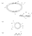
- Figs. 3(a) and 3(b) show a second embodiment of the corrugated spacer member 5 mounted in the plate-type heat exchanger of the present invention, wherein Fig. 3(a) shows a perspective view of the second embodiment of the corrugated spacer member 5 as a whole, and Fig. 3(b) shows an enlarged perspective view of an essential part of the second embodiment of the corrugated spacer member 5.
- This second embodiment of the corrugated spacer member 5 has its half constructed of a first corrugated portion 6 and the remaining half thereof constructed of a second corrugated portion 7.
- the second corrugated portion 7 of the spacer member 5 has the direction of the amplitude of its corrugation coincide with the direction of the radius of the corrugated spacer member 5.
- the first corrugated portion 6 of the spacer member 5 has the direction of the amplitude of its corrugation coincide with a direction perpendicular to the plane of the spacer member 5.
- its first corrugated portion 6 is integrally connected with the corresponding second corrugated portion 7 through a pair of twisted portions 11.
- the first corrugated portion 6 is twisted through an angle of substantially 90 degrees relative to the corresponding second corrugated portion 7.
- the second corrugated portion 7 of the spacer member 5 is disposed adjacent to each of opposite end portions of the heat exchanger elements 4, wherein these opposite end portions lie on the longitudinal axis of the heat exchanger element 4.
- the first corrugated portion 6 of the spacer member 5 is disposed adjacent to an intermediate portion of the heat exchanger element 4.
- Fig. 4 shows a third embodiment of the corrugated spacer member 5 of the plate-type heat exchanger of the present invention.
- the second corrugated portion 7 of the spacer member 5 is smaller in pitch than the corresponding first corrugated portion 6 of the same spacer member 5.
- the second corrugated portion 7 of the spacer member 5 is disposed adjacent to each of the opposite edge portions of the heat exchanger element 4, wherein these opposite edge portions lie on the longitudinal axis of the heat exchanger element 4. Due to the above arrangement, the heat-exchanging medium passing through the second corrugated portion 7 of the spacer member 5 is smaller in flow rate than that passing through the first corrugated portion 6 of the same spacer member 5.
- the plate-type heat exchanger of the present invention having the above construction has the following action and effect: namely, since its planar spacer member 5 is constructed of the annular metal plate having been corrugated, it is possible to uniformly hold and connect the inlet/outlet openings 1 of the heat exchanger elements 4 with each other through these planar spacer members 5, which improves the plate-type heat exchanger of the present invention in resistance to pressure and in reliability in its brazed or soldered connection portions. Further, since the corrugated spacer member 5 preventing the inlet/outlet opening 1 from deforming is constructed of the corrugated annular article, it is possible for the heat exchanger element 4 to realize a considerable weight reduction. Furthermore, due to such considerable weight reduction, it is possible to improve the plate-type heat exchanger of the present invention in stirring efficiency of the heat-exchanging medium, and, therefore in heat transfer efficiency as a whole.
- the plate-type heat exchanger of the present invention is improved in its brazing or soldering efficiency in manufacturing, which makes it possible to heat the corrugated spacer member 5 to a predetermined temperature in a time shorter than that required to heat the conventional reinforcement to the predetermined temperature in a brazing or a soldering process in manufacturing the heat exchanger.
- the corrugated spacer member 5 of the present invention it is possible for the corrugated spacer member 5 of the present invention to absorb any thermal stress in use, which prevent the corrugated spacer member 5 from cracking.
- the corrugated spacer member 5 of the present invention to save material cost in manufacturing, which makes it possible to realize a considerable cost reduction of the plate-type heat exchanger of the present invention in manufacturing.
- its corrugated spacer member 5 has the direction of the amplitude of its corrugation coincide with the direction of the thickness of the heat exchanger element 4 over the entire circumference thereof, which makes it possible to produce the corrugated spacer member 5 with uniform and high accuracy in an easy manner.
- its corrugated spacer member 5 is constructed of a metal strip member having been corrugated and formed into an annular shape, which makes it possible to save the material of the corrugated spacer member 5.
- its corrugated spacer member 5 is constructed of an annular spacer blank having punched out of a metal plate, wherein the annular spacer blank is corrugated to produce the corrugated spacer member 5.
- This type of the corrugated spacer member 5 is excellent in accuracy and easy in manufacturing.
- its corrugated spacer member 5 is constructed of the first corrugated portion 6 and the second corrugated portion 7, which makes it possible for the second corrugated portion 7 of the spacer member 5 to prevent the heat-exchanging medium from flowing toward each of the opposite end portions of the heat exchanger element 4, and, therefore to have the heat-exchanging medium smoothly flow from one of the inlet/outlet openings 1 to the other of the inlet/outlet openings 1. Due to this smooth flow of the heat-exchanging medium, resistance to flow is considerably reduced in the plate-type heat exchanger of the present invention as a whole.
- the corrugated spacer member 5 has its first corrugated portion 6 twisted through an angle of substantially 90 degrees relative to the remaining second corrugated portion 7. Due to this construction, it is possible to produce this type of corrugated spacer member 5 in an easy manner, and also to realize a considerable reduction in the number of necessary parts of the plate-type heat exchanger of the present invention.
- a plurality of the heat exchanger elements 4 are stacked on top of each other in layers, wherein the parts of each of the heat exchanger elements 4 are brazed or soldered to each other.
- the corrugated spacer member 5 is interposed between a pair of the elongated plates 2, 3 to prevent each of the inlet/outlet openings 1 from deforming in a brazing or a soldering process in manufacturing, which makes it possible to produce the plate-type heat exchanger of the present invention which is excellent in accuracy and in fluid-sealing properties.
Landscapes
- Engineering & Computer Science (AREA)
- Physics & Mathematics (AREA)
- Thermal Sciences (AREA)
- Mechanical Engineering (AREA)
- General Engineering & Computer Science (AREA)
- Heat-Exchange Devices With Radiators And Conduit Assemblies (AREA)
Abstract
In a plate-type heat exchanger provided with a plurality
of heat exchanger elements (4) each constructed of a pair of
elongated plates (2, 3) each of which is provided with a pair
of inlet/outlet openings (1) in its opposite end portions, a
corrugated spacer member (5) for reinforcing each of the
inlet/outlet openings (1) is reduced in weight and improved
in heat exchanging properties. The spacer member (5) assuming
an annular corrugated shape is interposed between vertically
aligned adjacent ones of the inlet/outlet openings (1) of the
stacked elongated plates (2, 3) in the heat exchanger element
(4). This corrugated spacer member (5) is constructed of a metal
plate corrugated over its entire circumference.
Description
- The present invention relates to a plate-type heat exchanger and a method of its production, wherein the heat exchanger: is excellent in resistance to pressure; is reduced in weight; is improved in thermal transfer efficiency in its corrugated spacer members; and, comprises a plurality of heat exchanger elements stacked on top of each other in layers, wherein each of these elements comprises a plurality of parallel dish-like elongated plates which are spaced apart from each other through the corrugated spacer members.
- In a conventional plate-type heat exchanger, a flat fluid flow passage is formed by connecting a pair of elongated dish-like plates with each other in their peripheral edge portions. Each of these dish-like elongated plates is provided with a pair of heat-exchanging medium inlet/outlet openings in its opposite end portions. Further, in the interior of the heat exchanger, a reinforcing spacer or reinforcement 8 such as shown in Fig. 9 has its upper and lower surfaces soldered to the corresponding surfaces of the dish-like plates in the vicinities or peripheral areas of the inlet/outlet openings of the dish-like plates, so that a
heat exchanger element 4 is constructed of such pair of the dish-like plates and the reinforcements 8 interposed therebetween. Incidentally, in the reinforcement 8 shown in Fig. 9, the upper surface and the lower surface thereof mentioned above are oppositely disposed from each other in the width direction of the reinforcement 8. Theheat exchanger elements 4 thus constructed are then stacked on top of each other in layers to form the conventional heat exchanger. - The reinforcement 8 mounted inside the
heat exchanger element 4 assumes a substantially horseshoe-like shape as shown in Fig. 9. With this reinforcement 8, a half the circumference or peripheral area of the inlet/outlet opening of the dish-like plate is blocked with respect to a heat-exchanging medium or fulid. - The reinforcement 8 serving as the conventional horseshoe-like spacer such as shown in Fig. 9 reinforces only a half of a peripheral edge portion of the inlet/outlet opening. In other words, the remaining half of such peripheral edge portion of the inlet/outlet opening remains poor in mechanical strength.
- Particularly, in this plate-type heat exchanger, it is necessary to apply pressure onto a plurality of its heat exchanger elements in the width direction thereof when these elements are stacked on top of each other in layers in their soldering process and like fastening processes.
- In this case, however, it is difficult to uniformly connect the edge portions of the inlet/outlet openings of these elements with each other, because a half the edge portion of each of these inlet/outlet openings lacks the reinforcement 8. Further, these inlet/outlet openings of the heat exchanger elements are relatively poor in resistance to pressure.
- Further, the reinforcement 8 is heavy for its size, and, makes it difficult to realize any substantial weight reduction of the heat exchanger as a whole. Further, the reinforcement 8 itself makes substantially no contribution to improvements in heat exchanging performance of the heat exchanger.
- Under such circumstances, the present invention was made to solve the above problems inherent in the conventional heat exchangers.
- Consequently, it would be desirable to be able to provide a plate-type heat exchanger and a method of its production, wherein: the plate-type heat exchanger is sufficiently reinforced in its inlet/outlet openings of a plurality of heat exchanger elements; and, these heat exchanger elements are reduced in weight and improved in their heat transfer properties, wherein, more specifically, each of its spacer members is reduced in heat capacity, which improves the spacer member itself in soldering properties and also in heat transfer properties relative to the elongated plates of the heat exchanger elements.
- It would also be desirable to be able to provide a plate-type heat exchanger and a method of its production, wherein: a fluid smoothly flows from one of a pair of inlet/outlet openings of the plate-type heat exchanger to the other of these inlet/outlet openings; and, resistance to flow of the fluid is minimized.
- In accordance with a first aspect of the present invention, there is provided:
- in a plate-type heat exchanger comprising a plurality of heat exchanger elements each constructed of a pair of elongated plates at least one of which assumes a dish-like shape, each of the elongated plates being provided with a pair of inlet/outlet openings in its opposite end portions to permit a heat-exchanging medium to pass therethrough, the elongated plates being connected with each other in their peripheral edge portions, the elements being stacked on top of each other in layers so as to have their inlet/outlet openings aligned with each other in a manner such that each of the elements forms therein a flat fluid passage extending from one of the inlet/outlet openings to the other of the inlet/outlet openings, the improvement wherein:
- a substantially planar and annular corrugated spacer member is interposed between adjacent ones of the inlet/outlet openings of each of the elements to connect the pair of the elongated plates of each of the elements in peripheral edge portions of the inlet/outlet openings through a brazing process or a soldering process; and
- the corrugated spacer member is constructed of a corrugated metal plate assuming an elongated shape at least a part of which has the direction of the amplitude of its corrugation coincide with the direction of the thickness of each of the elements.
-
- In this plate-type heat exchanger, since the corrugated spacer member is constructed of the corrugated metal plate assuming a planar annular shape, it is possible to uniformly hold the inlet/outlet openings of the heat exchanger elements. Due to such uniform holding of the inlet/outlet openings of the elements, it is possible to improve the plate-type heat exchanger of the present invention in resistance to pressure and also in reliability in its connection portions connected through a brazing process or a soldering process. Further, it is possible for the plate-type heat exchanger of the present invention to realize a considerable reduction in weight. In operation, in the plate-type heat exchanger of the present invention, when the heat-exchanging medium passes through the corrugated spacer member, heat transfer is enhanced due to the corrugated shape of the spacer member, i.e., due to its sufficient stirring action and effect. Further, the spacer member of the present invention is small in heat capacity, which makes it possible to braze or solder the spacer member to each of the elongated plates in an easy manner.
- In accordance with a second aspect of the present invention, there is provided:
the plate-type heat exchanger as set forth in the first aspect of the present invention, wherein the corrugated spacer member has the direction of the amplitude of its corrugation coincide with the direction of the thickness of each of the heat exchanger elements over the entire circumference of the corrugated spacer member. - In accordance with a third aspect of the present invention, there is provided:
the plate-type heat exchanger as set forth in the fist or the second aspect of the present invention, wherein the corrugated spacer member is constructed of an elongated corrugated strip member having been formed into an annular shape. - In accordance with a fourth aspect of the present invention, there is provided:
the plate-type heat exchanger as set forth in the second aspect of the present invention, wherein the metal plate to be formed into the corrugated spacer member is punched to produce an annular spacer blank, and then the spacer blank is corrugated to form the corrugated spacer member. - In accordance with a fifth aspect of the present invention, there is provided:
the plate-type heat exchanger as set forth in the first aspect of the present invention, wherein: a substantially half the circumference of the corrugated spacer member has the direction of the amplitude of its corrugation coincide with the direction of the thickness of the heat exchanger element to form a first corrugated portion; the substantially remaining half the circumference of the corrugated spacer member has the direction of the amplitude of its corrugation coincide with the direction of the radius of the corrugated spacer member to form a second corrugated portion; and, the second corrugated portion is disposed adjacent to an outer edge side of one of opposite end portions of the heat exchanger element, which opposite end portions lie on a longitudinal axis of the heat exchanger element. - In the plate-type heat exchanger according to this fifth aspect of the present invention, it is possible to prevent the heat-exchanging medium having received in the heat exchanger element through the second corrugated portion of the spacer member from flowing out of this second corrugated portion of the spacer member, which makes it possible to smoothly flow the heat-exchanging medium from one of the inlet/outlet openings to the other, whereby the plate-type heat exchanger of the present invention is reduced in resistance to flow and improved in heat transfer efficiency.
- In accordance with a sixth aspect of the present invention, there is provided:
the plate-type heat exchanger as set forth in the fifth aspect of the present invention, wherein the corrugated spacer member is formed into an integral entity, and has the first corrugated portion twisted through an angle of substantially 90 degrees relative to the second corrugated portion. - In the plate-type heat exchanger according to this sixth aspect of the present invention, it is possible to simultaneously produce both the first and the second corrugated portions of the corrugated spacer member by using a single piece of the spacer member, which makes it possible to provide the corrugated spacer member simple in construction and excellent in performance.
- In accordance with a seventh aspect of the present invention, there is provided:
- a method for producing a plate-type heat exchanger, wherein the heat exchanger comprising a plurality of heat exchanger elements each constructed of a pair of elongated plates at least one of which assumes a dish-like shape, each of the elongated plates being provided with a pair of inlet/outlet openings in its opposite end portions to permit a heat-exchanging medium to pass therethrough, the elongated plates being connected with each other in their peripheral edge portions, the heat exchanger elements being stacked on top of each other in layers so as to have their inlet/outlet openings aligned with each other in a manner such that each of the heat exchanger elements forms therein a flat fluid passage extending from one of the inlet/outlet openings to the other of the inlet/outlet openings, wherein a substantially planar and annular corrugated spacer member is interposed between adjacent ones of the inlet/outlet openings of each of the heat exchanger elements to connect the pair of the elongated plates of each of the heat exchanger elements in peripheral edge portions of the inlet/outlet openings through a brazing process or a soldering process, wherein the corrugated spacer member is constructed of a corrugated metal plate assuming an elongated shape at least a part of which has the direction of the amplitude of its corrugation coincide with the direction of the thickness of each of the heat exchanger elements, the method comprising the steps of:
- having a plurality of the heat exchanger elements stacked on top of each other in layers so as to have them brought into press contact with other; and
- connecting the heat exchanger elements with each other by a brazing process or by a soldering process.
-
- In accordance with an eighth aspect of the present invention, there is provided:
the method for producing the plate-type heat exchanger as set forth in the seventh aspect of the present invention, wherein the corrugated spacer member has the direction of the amplitude of its corrugation coincide with the direction of the thickness of each of the heat exchanger elements over the entire circumference of the corrugated spacer member. - In accordance with a ninth aspect of the present invention, there is provided:
the method for producing the plate-type heat exchanger as set forth in the seventh or the eighth aspect of the present invention, wherein the corrugated spacer member is constructed of an elongated corrugated strip member having been formed into an annular shape. - In accordance with a tenth aspect of the present invention, there is provided:
the method for producing the plate-type heat exchanger as set forth in the eighth aspect of the present invention, wherein the metal plate to be formed into the corrugated spacer member is punched to produce an annular spacer blank, and then the spacer blank is corrugated to form the corrugated spacer member. - In accordance with an eleventh aspect of the present invention, there is provided:
the method for producing the plate-type heat exchanger as set forth in the seventh aspect of the present invention, wherein: a substantially half the circumference of the corrugated spacer member has the direction of the amplitude of its corrugation coincide with the direction of the thickness of the heat exchanger element to form a first corrugated portion; the substantially remaining half the circumference of the corrugated spacer member has the direction of the amplitude of its corrugation coincide with the direction of the radius of the corrugated spacer member to form a second corrugated portion; and, the second corrugated portion is disposed adjacent to an outer edge side of one of opposite end portions of the element, which opposite end portions lie on a longitudinal axis of the heat exchanger element. - In accordance with a twelfth aspect of the present invention, there is provided:
the method for producing the plate-type heat exchanger as set forth in the eleventh aspect of the present invention, wherein the corrugated spacer member is formed into an integral entity, and has the first corrugated portion twisted through an angle of substantially 90 degrees relative to the second corrugated portion. - In the drawings:
- Fig. 1 is an exploded perspective view of an essential part of the plate-type heat exchanger of the present invention;
- Fig. 2 is a longitudinal sectional view of the essential part of the plate-type heat exchanger of the present invention shown in Fig. 1;
- Fig. 3(a) is a perspective view of a second embodiment of a corrugated spacer member used in the heat exchanger of the present invention shown in Fig. 1;
- Fig. 3(b) is an enlarged perspective view of an essential part of the corrugated spacer member shown in Fig. 3(a);
- Fig. 4 is a plan view of a third embodiment of the corrugated spacer member shown in Fig. 1;
- Fig. 5 is a side view of the third embodiment of the corrugated spacer member shown in Fig. 4;
- Fig. 6 is a perspective view of a corrugated member from which the corrugated spacer member of the present invention shown in Fig. 1 is formed, illustrating a first step of a method for producing the corrugated spacer member of the plate-type heat exchanger shown in Fig. 1;
- Fig. 7 is a perspective view of the corrugated spacer member formed from the corrugated member shown in Fig. 6, illustrating a second step of the method for producing the corrugated spacer member of the plate-type heat exchanger shown in Fig. 1;
- Fig. 8 is a perspective view of the corrugated spacer member formed from the corrugated member shown in Fig. 6, illustrating a second embodiment of the method for producing the corrugated spacer member of the plate-type heat exchanger shown in Fig. 1; and
- Fig. 9 is a perspective view of the conventional spacer member or reinforcement.
-
- Now, best modes of the present invention will be described in detail with reference to the accompanying drawings.
- Shown in Fig. 1 is a perspective view of an essential part of a
heat exchanger elements 4 used in a plate-type heat exchanger according to a first aspect of the present invention. This essential part of theheat exchanger element 4 is shown also in longitudinal section in Fig. 2. - In the plate-type heat exchanger of the present invention, as is clear from Fig. 1, an
upper one 2 of a pair ofelongated plates elongated plate 2. Each of the inlet/outlet openings 1 of theupper one 2 of theelongated plates elongated plate 2 is provided with a small horizontal flange portion in its outer peripheral portion. - On the other hand, the other (i.e., lower one) 3 of the
elongated plates elongated plate 2, and has its inlet/outlet openings 1 aligned with the corresponding inlet/outlet openings 1 of the upperelongated plate 2. The outer peripheral portion of the lowerelongated plate 3 is bent upwardly as viewed in Fig. 1 to form a small vertical flange portion. In the assembly operation of the plate-type heat exchanger of the present invention, an inner surface of the vertical flange portion of the lowerelongated plate 3 is brought into contact with an outer peripheral edge portion of the horizontal flange portion of the upperelongated plate 2. Then, the vertical flange portion of the lowerelongated plate 3 is turned radially inwardly to have its inner surface brought into press-contact with an upper surface of the horizontal flange portion of the upperelongated plate 2 over the entire peripheral portion of the lowerelongated plate 3, so that the upperelongated plate 2 is firmly fastened to the corresponding lowerelongated plate 3. In this assembly operation, each of thecorrugated spacer members 5 is interposed between theelongated plates heat exchanger element 4. - This
corrugated spacer member 5 is constructed of a metal plate assuming a corrugated elongated shape, which has the direction of the amplitude of its corrugation coincide with the direction of the thickness of theheat exchanger element 4 over the entire circumference of thespacer member 5. In production of thecorrugated spacer member 5, for example, first of all, as shown in Fig. 6, a straight elongated metal plate is formed, and corrugated to have its corrugation lie in a vertical plane. After that, as shown in Fig. 7, the elongated metal plate thus corrugated is formed into an annular shape as a whole, in which opposite end portions of the metal plate are brought into contact with each other, or oppositely disposed from each other through a slight clearance "t". Alternatively, as shown in Fig. 8, thecorrugated spacer member 5 is constructed of an annular spacer blank having been punched out of a metal plate and corrugated over its entire circumference. - As for the shape of the corrugation, the
corrugated spacer member 5 may assume trapezoidal corrugation shapes, square corrugation shapes, or smooth sinusoidal corrugation shapes. - In the
heat exchanger element 4 shown in Fig. 2, the amplitude of the corrugation of thecorrugated spacer member 5 is half the distance between theelongated plates heat exchanger elements 4, provided that thecorrugated spacer member 5 has both the upper surfaces of its crest portions and the lower surfaces of its root portions brought into contact with an inner surface of the upperelongated plate 2 and an inner surface of the lowerelongated plate 3, respectively. In this first embodiment of thecorrugated spacer member 5 shown in Fig. 1, the direction of the amplitude of its corrugation coincides with the direction of the thickness of each of theelongated plates corrugated spacer member 5, the corrugation of thecorrugated spacer member 5 does not very in pitch over its entire circumstance. As shown in Fig. 5, however, it is also possible for thecorrugated spacer member 5 to have its corrugation vary in pitch so as to have a pitch P1 and a pitch P2 . Further, in the first embodiment of thecorrugated spacer member 5 shown in Fig. 1, though thecorrugated spacer member 5 is constructed of a single piece of an annular article, it is also possible for thecorrugated spacer member 5 to be constructed of a pair of semicircular articles which have their opposite end portions connected with each other to form an annular shape. - As is clear from Fig. 1, in the assembly operation of the plate-type heat exchanger of the present invention, the
corrugated spacer members 5 are mounted inside the bulging portions 9 of the inlet/outlet openings 1 of each of theheat exchanger elements 4. At this time, aninner fin member 12 is also mounted inside each of theheat exchanger elements 4. Then, as shown in Fig. 2, a plurality of theheat exchanger elements 4 thus constructed are stacked on top of each other in layers. At this time, anouter fin member 13 is interposed between adjacent ones of the thus stackedheat exchanger elements 4 to complete the assembly operation of the heat exchanger of the present invention. Incidentally, as shown in Fig. 2, the lowermost one of the lowerelongated plates 3 is not provided with the inlet/outlet openings 1. Further, as shown in Fig. 1, the uppermost one of the upperelongated plates 2 has its upper surface disposed adjacent to anupper end plate 10 which has a pair of its openings aligned with the inlet/outlet openings 1 of theheat exchanger elements 4 having been stacked. Disposed adjacent to an upper surface of each of the pair of the openings of theupper end plate 10 is aboss member 14. - In operation, as shown in Fig. 2, the plate-type heat exchanger of the present invention having the above construction receives the heat-exchanging medium, for example such as a high-temperature fluid and the like in one of its inlet/outlet openings 1 (the other of the inlet/outlet openings 1 is not shown) . The high-temperature fluid thus received flows into the interior of each of the
heat exchanger elements 4, so that heat exchanging is conducted between: the high-temperature fluid passing through the interior of each of theheat exchanger elements 4; and, a cooling air or water passing outside each of theheat exchanger elements 4. - Figs. 3(a) and 3(b) show a second embodiment of the
corrugated spacer member 5 mounted in the plate-type heat exchanger of the present invention, wherein Fig. 3(a) shows a perspective view of the second embodiment of thecorrugated spacer member 5 as a whole, and Fig. 3(b) shows an enlarged perspective view of an essential part of the second embodiment of thecorrugated spacer member 5. - This second embodiment of the
corrugated spacer member 5 has its half constructed of a firstcorrugated portion 6 and the remaining half thereof constructed of a secondcorrugated portion 7. As is clear from Fig. 3(a), the secondcorrugated portion 7 of thespacer member 5 has the direction of the amplitude of its corrugation coincide with the direction of the radius of thecorrugated spacer member 5. On the other hand, the firstcorrugated portion 6 of thespacer member 5 has the direction of the amplitude of its corrugation coincide with a direction perpendicular to the plane of thespacer member 5. In this second embodiment of thecorrugated spacer member 5, its firstcorrugated portion 6 is integrally connected with the corresponding secondcorrugated portion 7 through a pair of twisted portions 11. In other words, in each of these twisted portions 11, the firstcorrugated portion 6 is twisted through an angle of substantially 90 degrees relative to the corresponding secondcorrugated portion 7. In installation, the secondcorrugated portion 7 of thespacer member 5 is disposed adjacent to each of opposite end portions of theheat exchanger elements 4, wherein these opposite end portions lie on the longitudinal axis of theheat exchanger element 4. On the other hand, the firstcorrugated portion 6 of thespacer member 5 is disposed adjacent to an intermediate portion of theheat exchanger element 4. Due to the above arrangement, it is possible to prevent the heat-exchanging medium having entered each of theheat exchanger elements 4 from flowing out through the secondcorrugated portion 7 of thespacer member 5, which makes it possible for the heat-exchanging medium to smoothly flow from one of the inlet/outlet openings 1 to the other of the inlet/outlet openings 1. - Fig. 4 shows a third embodiment of the
corrugated spacer member 5 of the plate-type heat exchanger of the present invention. In this third embodiment of thecorrugated spacer member 5, the secondcorrugated portion 7 of thespacer member 5 is smaller in pitch than the corresponding firstcorrugated portion 6 of thesame spacer member 5. Also in this case, the secondcorrugated portion 7 of thespacer member 5 is disposed adjacent to each of the opposite edge portions of theheat exchanger element 4, wherein these opposite edge portions lie on the longitudinal axis of theheat exchanger element 4. Due to the above arrangement, the heat-exchanging medium passing through the secondcorrugated portion 7 of thespacer member 5 is smaller in flow rate than that passing through the firstcorrugated portion 6 of thesame spacer member 5. - The plate-type heat exchanger of the present invention having the above construction has the following action and effect: namely, since its
planar spacer member 5 is constructed of the annular metal plate having been corrugated, it is possible to uniformly hold and connect the inlet/outlet openings 1 of theheat exchanger elements 4 with each other through theseplanar spacer members 5, which improves the plate-type heat exchanger of the present invention in resistance to pressure and in reliability in its brazed or soldered connection portions. Further, since thecorrugated spacer member 5 preventing the inlet/outlet opening 1 from deforming is constructed of the corrugated annular article, it is possible for theheat exchanger element 4 to realize a considerable weight reduction. Furthermore, due to such considerable weight reduction, it is possible to improve the plate-type heat exchanger of the present invention in stirring efficiency of the heat-exchanging medium, and, therefore in heat transfer efficiency as a whole. - In other words, since the
corrugated spacer member 5 is reduced in heat capacity, the plate-type heat exchanger of the present invention is improved in its brazing or soldering efficiency in manufacturing, which makes it possible to heat thecorrugated spacer member 5 to a predetermined temperature in a time shorter than that required to heat the conventional reinforcement to the predetermined temperature in a brazing or a soldering process in manufacturing the heat exchanger. In operation, it is possible for thecorrugated spacer member 5 of the present invention to absorb any thermal stress in use, which prevent thecorrugated spacer member 5 from cracking. Further, it is also possible for thecorrugated spacer member 5 of the present invention to save material cost in manufacturing, which makes it possible to realize a considerable cost reduction of the plate-type heat exchanger of the present invention in manufacturing. - On the other hand, in the plate-type heat exchanger according to a second aspect of the present invention, its
corrugated spacer member 5 has the direction of the amplitude of its corrugation coincide with the direction of the thickness of theheat exchanger element 4 over the entire circumference thereof, which makes it possible to produce thecorrugated spacer member 5 with uniform and high accuracy in an easy manner. - In the plate-type heat exchanger according to a third aspect of the present invention, its
corrugated spacer member 5 is constructed of a metal strip member having been corrugated and formed into an annular shape, which makes it possible to save the material of thecorrugated spacer member 5. - In the plate-type heat exchanger according to a fourth aspect of the present invention, its
corrugated spacer member 5 is constructed of an annular spacer blank having punched out of a metal plate, wherein the annular spacer blank is corrugated to produce thecorrugated spacer member 5. This type of thecorrugated spacer member 5 is excellent in accuracy and easy in manufacturing. - In the plate-type heat exchanger according to a fifth aspect of the present invention, its
corrugated spacer member 5 is constructed of the firstcorrugated portion 6 and the secondcorrugated portion 7, which makes it possible for the secondcorrugated portion 7 of thespacer member 5 to prevent the heat-exchanging medium from flowing toward each of the opposite end portions of theheat exchanger element 4, and, therefore to have the heat-exchanging medium smoothly flow from one of the inlet/outlet openings 1 to the other of the inlet/outlet openings 1. Due to this smooth flow of the heat-exchanging medium, resistance to flow is considerably reduced in the plate-type heat exchanger of the present invention as a whole. - In the plate-type heat exchanger according to a sixth aspect of the present invention, the
corrugated spacer member 5 has its firstcorrugated portion 6 twisted through an angle of substantially 90 degrees relative to the remaining secondcorrugated portion 7. Due to this construction, it is possible to produce this type ofcorrugated spacer member 5 in an easy manner, and also to realize a considerable reduction in the number of necessary parts of the plate-type heat exchanger of the present invention. - In the plate-type heat exchanger according to a seventh aspect of the present invention, a plurality of the
heat exchanger elements 4 are stacked on top of each other in layers, wherein the parts of each of theheat exchanger elements 4 are brazed or soldered to each other. In each of theheat exchanger elements 4, thecorrugated spacer member 5 is interposed between a pair of theelongated plates
Claims (12)
- A plate-type heat exchanger comprising a plurality of heat exchanger elements (4) each constructed of a pair of elongated plates (2, 3) at least one of which assumes a dish-like shape, each of said elongated plates (2, 3) being provided with a pair of inlet/outlet openings (1) in its opposite end portions to permit a heat-exchanging medium to pass therethrough, said elongated plates (2, 3) being connected with each other in their peripheral edge portions, said heat exchanger elements (4) being stacked on top of each other in layers so as to have their inlet/outlet openings (1) aligned with each other in a manner such that each of said elements (4) forms therein a flat fluid passage extending from one of said inlet/outlet openings (1) thereof to the other of said inlet/outlet openings (1) thereof, characterised in that:a substantially planar and annular corrugated spacer member (5) is interposed between adjacent ones of said inlet/outlet openings (1) of each of said heat exchanger elements (4) to connect said pair of said elongated plates (2, 3) of each of said heat exchanger elements (4) in peripheral portions of said inlet/outlet openings (1) through a brazing process or a soldering process; andsaid corrugated spacer member (5) is constructed of a corrugated metal plate assuming an elongated shape at least a part of which has the direction of the amplitude of its corrugation coincide with the direction of the thickness of each of said heat exchanger elements (4).
- The plate-type heat exchanger as set forth in claim 1, wherein said corrugated spacer member (5) has the direction of the amplitude of its corrugation coincide with the direction of the thickness of each of said heat exchanger elements (4) over the entire circumference of said corrugated spacer member (5).
- The plate-type heat exchanger as set forth in claim 1 or 2, wherein said corrugated spacer member (5) is constructed of an elongated corrugated strip member having been formed into an annular shape.
- The plate-type heat exchanger as set forth in claim 2, wherein: said metal plate to be formed into said corrugated spacer member (5) is punched to produce an annular spacer blank; and, said spacer blank is corrugated to form said corrugated spacer member (5).
- The plate-type heat exchanger as set forth in claim 1, wherein: a substantially half the circumference of said corrugated spacer member (5) has the direction of the amplitude of its corrugation coincide with the direction of the thickness of said heat exchanger element (4) to form a first corrugated portion (6); the substantially remaining half the circumference of said corrugated spacer member (5) has the direction of the amplitude of its corrugation coincide with the direction of the radius of said corrugated spacer member (5) to form a second corrugated portion (7); and, said second corrugated portion (7) is disposed adjacent to an outer edge side of one of opposite end portions of said heat exchanger element (4), which opposite end portions lie on a longitudinal axis of said heat exchanger element (4).
- The plate-type heat exchanger as set forth in claim 5, wherein: said corrugated spacer member (5) is formed into an integral entity; and, said first corrugated portion (6) of said corrugated spacer member (5) is twisted through an angle of substantially 90 degrees relative to said second corrugated portion (7) of said corrugated spacer member (5).
- A method for producing a plate-type heat exchanger, wherein said heat exchanger comprising a plurality of heat exchanger elements (4) each constructed of a pair of elongated plates (2, 3) at least one of which assumes a dish-like shape, each of said elongated plates (2, 3) being provided with a pair of inlet/outlet openings (1) in its opposite end portions to permit a heat-exchanging medium to pass therethrough, said elongated plates (2, 3) being connected with each other in their peripheral edge portions, said heat exchanger elements (4) being stacked on top of each other in layers so as to have their inlet/outlet openings (1) aligned with each other in a manner such that each of said heat exchanger elements (4) forms therein a flat fluid passage extending from one of said inlet/outlet openings (1) to the other of said inlet/outlet openings (1), wherein a substantially planar and annular corrugated spacer member (5) is interposed between adjacent ones of said inlet/outlet openings (1) of each of said heat exchanger elements (4) to connect said pair of said elongated plates (2, 3) of each of said heat exchanger elements (4) in peripheral portions of said inlet/outlet openings (1) through a brazing process or a soldering process, wherein said corrugated spacer member (5) is constructed of a corrugated metal plate assuming an elongated shape at least a part of which has the direction of the amplitude of its corrugation coincide with the direction of the thickness of each of said heat exchanger elements (4), characterised by the steps of:having a plurality of said heat exchanger elements (4) stacked on top of each other in layers so as to have them brought into press contact with other; andconnecting said heat exchanger elements (4) with each other by a brazing process or by a soldering process.
- The method for producing the plate-type heat exchanger as set forth in claim 7, wherein said corrugated spacer member (5) has the direction of the amplitude of its corrugation coincide with the direction of the thickness of each of said neat exchanger elements (4) over the entire circumference of said corrugated spacer member (5).
- The method for producing the plate-type heat exchanger as set forth in claim 7 or 8, wherein said corrugated spacer member (5) is constructed of an elongated corrugated strip member having been formed into an annular shape.
- The method for producing the plate-type heat exchanger as set forth in claim 8, wherein: said metal plate to be formed into said corrugated spacer member (5) is punched to produce an annular spacer blank; and, said spacer blank is corrugated to form said corrugated spacer member (5).
- The method for producing the plate-type heat exchanger as set forth in claim 7, wherein: a substantially half the circumference of said corrugated spacer member (5) has the direction of the amplitude of its corrugation coincide with the direction of the thickness of said heat exchanger element (4) to form a first corrugated portion (6); the substantially remaining half the circumference of said corrugated spacer member (5) has the direction of the amplitude of its corrugation coincide with the direction of the radius of said corrugated spacer member (5) to form a second corrugated portion (7); and, said second corrugated portion (7) is disposed adjacent to an outer edge side of one of opposite end portions of said heat exchanger element (4), which opposite end portions lie on a longitudinal axis of said heat exchanger element (4).
- The method for producing the plate-type heat exchanger as set forth in claim 11, wherein: said corrugated spacer member (5) is formed into an integral entity; and, said first corrugated portion (6) of said corrugated spacer member (5) is twisted through an angle of substantially 90 degrees relative to said second corrugated portion (7) of said corrugated spacer member (5).
Priority Applications (1)
| Application Number | Priority Date | Filing Date | Title |
|---|---|---|---|
| EP99307197A EP1083398A1 (en) | 1999-09-10 | 1999-09-10 | Plate-type heat exchanger and method of its production |
Applications Claiming Priority (1)
| Application Number | Priority Date | Filing Date | Title |
|---|---|---|---|
| EP99307197A EP1083398A1 (en) | 1999-09-10 | 1999-09-10 | Plate-type heat exchanger and method of its production |
Publications (1)
| Publication Number | Publication Date |
|---|---|
| EP1083398A1 true EP1083398A1 (en) | 2001-03-14 |
Family
ID=8241616
Family Applications (1)
| Application Number | Title | Priority Date | Filing Date |
|---|---|---|---|
| EP99307197A Withdrawn EP1083398A1 (en) | 1999-09-10 | 1999-09-10 | Plate-type heat exchanger and method of its production |
Country Status (1)
| Country | Link |
|---|---|
| EP (1) | EP1083398A1 (en) |
Cited By (9)
| Publication number | Priority date | Publication date | Assignee | Title |
|---|---|---|---|---|
| EP1281921A3 (en) * | 2001-08-03 | 2003-12-17 | Ingersoll-Rand Energy Systems Corporation | Counterflow plate-fin heat exchanger with extended header fin |
| US6991026B2 (en) | 2004-06-21 | 2006-01-31 | Ingersoll-Rand Energy Systems | Heat exchanger with header tubes |
| WO2009123519A1 (en) * | 2008-04-04 | 2009-10-08 | Alfa Laval Corporate Ab | A plate heat exchanger |
| EP2336698A1 (en) * | 2009-12-16 | 2011-06-22 | Delphi Technologies, Inc. | Plate-type heat exchanger with reinforcement insert piece |
| DE102010036664A1 (en) * | 2010-07-27 | 2012-02-02 | Peter Rehberg | Plate heat exchanger has circular holes that are provided in the upper and lower portions of each heat transfer plate, and are supported with U-shaped tabs |
| CN102958723A (en) * | 2010-10-07 | 2013-03-06 | 三菱重工业株式会社 | Heat-medium heating device and vehicle air conditioning device provided with same |
| DE102014005149A1 (en) | 2014-04-08 | 2015-10-08 | Modine Manufacturing Company | In a housing located brazed heat exchanger |
| US20170016680A1 (en) * | 2014-03-07 | 2017-01-19 | Danfoss Micro Channel Heat Exchanger (Jiaxing) Co., Ltd. | Heat exchange plate for plate-type heat exchanger and plate-type heat... |
| DE102015220579A1 (en) | 2015-10-21 | 2017-04-27 | Mahle International Gmbh | Stacked-plate heat exchanger |
Citations (5)
| Publication number | Priority date | Publication date | Assignee | Title |
|---|---|---|---|---|
| GB654395A (en) * | 1942-05-22 | 1951-06-13 | Gyorgy Jendrassik | Improvements in or relating to plate heat exchangers for fluids |
| US2782010A (en) * | 1948-12-18 | 1957-02-19 | Modine Mfg Co | Heat exchanger |
| WO1988009474A1 (en) * | 1987-05-29 | 1988-12-01 | Alfa-Laval Thermal Ab | Plate heat exchanger having permanently joined plates |
| WO1990013394A1 (en) * | 1989-04-28 | 1990-11-15 | Torell Ab | Plate heat exchanger and method for its manufacture |
| WO1995000810A1 (en) * | 1993-06-17 | 1995-01-05 | Alfa Laval Thermal Ab | Plate heat exchanger |
-
1999
- 1999-09-10 EP EP99307197A patent/EP1083398A1/en not_active Withdrawn
Patent Citations (5)
| Publication number | Priority date | Publication date | Assignee | Title |
|---|---|---|---|---|
| GB654395A (en) * | 1942-05-22 | 1951-06-13 | Gyorgy Jendrassik | Improvements in or relating to plate heat exchangers for fluids |
| US2782010A (en) * | 1948-12-18 | 1957-02-19 | Modine Mfg Co | Heat exchanger |
| WO1988009474A1 (en) * | 1987-05-29 | 1988-12-01 | Alfa-Laval Thermal Ab | Plate heat exchanger having permanently joined plates |
| WO1990013394A1 (en) * | 1989-04-28 | 1990-11-15 | Torell Ab | Plate heat exchanger and method for its manufacture |
| WO1995000810A1 (en) * | 1993-06-17 | 1995-01-05 | Alfa Laval Thermal Ab | Plate heat exchanger |
Cited By (15)
| Publication number | Priority date | Publication date | Assignee | Title |
|---|---|---|---|---|
| EP1281921A3 (en) * | 2001-08-03 | 2003-12-17 | Ingersoll-Rand Energy Systems Corporation | Counterflow plate-fin heat exchanger with extended header fin |
| US6991026B2 (en) | 2004-06-21 | 2006-01-31 | Ingersoll-Rand Energy Systems | Heat exchanger with header tubes |
| KR101210673B1 (en) | 2008-04-04 | 2012-12-10 | 알파 라발 코포레이트 에이비 | A plate heat exchanger |
| WO2009123519A1 (en) * | 2008-04-04 | 2009-10-08 | Alfa Laval Corporate Ab | A plate heat exchanger |
| US8857504B2 (en) | 2008-04-04 | 2014-10-14 | Alfa Laval Corporate Ab | Plate heat exchanger |
| CN101983312B (en) * | 2008-04-04 | 2012-09-05 | 阿尔法拉瓦尔股份有限公司 | A plate heat exchanger |
| EP2336698A1 (en) * | 2009-12-16 | 2011-06-22 | Delphi Technologies, Inc. | Plate-type heat exchanger with reinforcement insert piece |
| DE102010036664A1 (en) * | 2010-07-27 | 2012-02-02 | Peter Rehberg | Plate heat exchanger has circular holes that are provided in the upper and lower portions of each heat transfer plate, and are supported with U-shaped tabs |
| DE102010036664B4 (en) * | 2010-07-27 | 2017-07-20 | Peter Rehberg | Plate heat exchangers |
| CN102958723A (en) * | 2010-10-07 | 2013-03-06 | 三菱重工业株式会社 | Heat-medium heating device and vehicle air conditioning device provided with same |
| US20170016680A1 (en) * | 2014-03-07 | 2017-01-19 | Danfoss Micro Channel Heat Exchanger (Jiaxing) Co., Ltd. | Heat exchange plate for plate-type heat exchanger and plate-type heat... |
| US10323883B2 (en) * | 2014-03-07 | 2019-06-18 | Danfoss Micro Channel Heat Exchanger (Jiaxing) Co., Ltd. | Heat exchange plate for plate-type heat exchanger and plate-type heat exchanger provided with said heat exchange plate |
| DE102014005149A1 (en) | 2014-04-08 | 2015-10-08 | Modine Manufacturing Company | In a housing located brazed heat exchanger |
| DE102014005149B4 (en) * | 2014-04-08 | 2016-01-21 | Modine Manufacturing Company | Brazed heat exchanger |
| DE102015220579A1 (en) | 2015-10-21 | 2017-04-27 | Mahle International Gmbh | Stacked-plate heat exchanger |
Similar Documents
| Publication | Publication Date | Title |
|---|---|---|
| US8678076B2 (en) | Heat exchanger with manifold strengthening protrusion | |
| EP2257757B2 (en) | A plate heat exchanger | |
| JP5403472B2 (en) | Plate heat exchanger | |
| CN1833153B (en) | Heat exchanger and method for the production thereof | |
| KR101210673B1 (en) | A plate heat exchanger | |
| EP1899671B1 (en) | A heat exchanger plate and plate package for a plate heat exchanger | |
| EP2257756B1 (en) | A plate heat exchanger | |
| US6962194B2 (en) | Brazed sheets with aligned openings and heat exchanger formed therefrom | |
| US20020148602A1 (en) | Heat exchanger core | |
| US20150285572A1 (en) | Brazed heat exchanger | |
| US20030131979A1 (en) | Oil cooler | |
| EP2257758B1 (en) | A plate heat exchanger | |
| US20050039899A1 (en) | Turbulator for heat exchanger | |
| JP7379539B2 (en) | Plate heat exchanger and method for manufacturing plate heat exchanger | |
| CN100516748C (en) | Heat exchanger | |
| CN111981877B (en) | Plate heat exchanger | |
| JPH11311491A (en) | Plate type heat exchanger and method of manufacturing the same | |
| CN114076545B (en) | Heat exchanger and air conditioner with same | |
| JP5084735B2 (en) | Enhanced manifold for heat exchanger header tank and header tank with such manifold |
Legal Events
| Date | Code | Title | Description |
|---|---|---|---|
| PUAI | Public reference made under article 153(3) epc to a published international application that has entered the european phase |
Free format text: ORIGINAL CODE: 0009012 |
|
| AK | Designated contracting states |
Kind code of ref document: A1 Designated state(s): DE FR GB |
|
| AX | Request for extension of the european patent |
Free format text: AL;LT;LV;MK;RO;SI |
|
| AKX | Designation fees paid |
Free format text: DE FR GB |
|
| STAA | Information on the status of an ep patent application or granted ep patent |
Free format text: STATUS: THE APPLICATION IS DEEMED TO BE WITHDRAWN |
|
| 18D | Application deemed to be withdrawn |
Effective date: 20010915 |