EP1083349A1 - Magnetic bearing device and vacuum pump - Google Patents
Magnetic bearing device and vacuum pump Download PDFInfo
- Publication number
- EP1083349A1 EP1083349A1 EP00913012A EP00913012A EP1083349A1 EP 1083349 A1 EP1083349 A1 EP 1083349A1 EP 00913012 A EP00913012 A EP 00913012A EP 00913012 A EP00913012 A EP 00913012A EP 1083349 A1 EP1083349 A1 EP 1083349A1
- Authority
- EP
- European Patent Office
- Prior art keywords
- corrugated
- magnetic bearing
- pair
- plate
- corrugated plate
- Prior art date
- Legal status (The legal status is an assumption and is not a legal conclusion. Google has not performed a legal analysis and makes no representation as to the accuracy of the status listed.)
- Granted
Links
Images




Classifications
-
- F—MECHANICAL ENGINEERING; LIGHTING; HEATING; WEAPONS; BLASTING
- F16—ENGINEERING ELEMENTS AND UNITS; GENERAL MEASURES FOR PRODUCING AND MAINTAINING EFFECTIVE FUNCTIONING OF MACHINES OR INSTALLATIONS; THERMAL INSULATION IN GENERAL
- F16C—SHAFTS; FLEXIBLE SHAFTS; ELEMENTS OR CRANKSHAFT MECHANISMS; ROTARY BODIES OTHER THAN GEARING ELEMENTS; BEARINGS
- F16C32/00—Bearings not otherwise provided for
- F16C32/04—Bearings not otherwise provided for using magnetic or electric supporting means
-
- F—MECHANICAL ENGINEERING; LIGHTING; HEATING; WEAPONS; BLASTING
- F04—POSITIVE - DISPLACEMENT MACHINES FOR LIQUIDS; PUMPS FOR LIQUIDS OR ELASTIC FLUIDS
- F04D—NON-POSITIVE-DISPLACEMENT PUMPS
- F04D29/00—Details, component parts, or accessories
- F04D29/05—Shafts or bearings, or assemblies thereof, specially adapted for elastic fluid pumps
- F04D29/056—Bearings
- F04D29/058—Bearings magnetic; electromagnetic
-
- F—MECHANICAL ENGINEERING; LIGHTING; HEATING; WEAPONS; BLASTING
- F04—POSITIVE - DISPLACEMENT MACHINES FOR LIQUIDS; PUMPS FOR LIQUIDS OR ELASTIC FLUIDS
- F04D—NON-POSITIVE-DISPLACEMENT PUMPS
- F04D19/00—Axial-flow pumps
- F04D19/02—Multi-stage pumps
- F04D19/04—Multi-stage pumps specially adapted to the production of a high vacuum, e.g. molecular pumps
- F04D19/048—Multi-stage pumps specially adapted to the production of a high vacuum, e.g. molecular pumps comprising magnetic bearings
-
- F—MECHANICAL ENGINEERING; LIGHTING; HEATING; WEAPONS; BLASTING
- F16—ENGINEERING ELEMENTS AND UNITS; GENERAL MEASURES FOR PRODUCING AND MAINTAINING EFFECTIVE FUNCTIONING OF MACHINES OR INSTALLATIONS; THERMAL INSULATION IN GENERAL
- F16C—SHAFTS; FLEXIBLE SHAFTS; ELEMENTS OR CRANKSHAFT MECHANISMS; ROTARY BODIES OTHER THAN GEARING ELEMENTS; BEARINGS
- F16C27/00—Elastic or yielding bearings or bearing supports, for exclusively rotary movement
- F16C27/04—Ball or roller bearings, e.g. with resilient rolling bodies
-
- F—MECHANICAL ENGINEERING; LIGHTING; HEATING; WEAPONS; BLASTING
- F16—ENGINEERING ELEMENTS AND UNITS; GENERAL MEASURES FOR PRODUCING AND MAINTAINING EFFECTIVE FUNCTIONING OF MACHINES OR INSTALLATIONS; THERMAL INSULATION IN GENERAL
- F16C—SHAFTS; FLEXIBLE SHAFTS; ELEMENTS OR CRANKSHAFT MECHANISMS; ROTARY BODIES OTHER THAN GEARING ELEMENTS; BEARINGS
- F16C32/00—Bearings not otherwise provided for
- F16C32/04—Bearings not otherwise provided for using magnetic or electric supporting means
- F16C32/0406—Magnetic bearings
- F16C32/044—Active magnetic bearings
- F16C32/0442—Active magnetic bearings with devices affected by abnormal, undesired or non-standard conditions such as shock-load, power outage, start-up or touchdown
-
- F—MECHANICAL ENGINEERING; LIGHTING; HEATING; WEAPONS; BLASTING
- F16—ENGINEERING ELEMENTS AND UNITS; GENERAL MEASURES FOR PRODUCING AND MAINTAINING EFFECTIVE FUNCTIONING OF MACHINES OR INSTALLATIONS; THERMAL INSULATION IN GENERAL
- F16C—SHAFTS; FLEXIBLE SHAFTS; ELEMENTS OR CRANKSHAFT MECHANISMS; ROTARY BODIES OTHER THAN GEARING ELEMENTS; BEARINGS
- F16C39/00—Relieving load on bearings
- F16C39/02—Relieving load on bearings using mechanical means
-
- F—MECHANICAL ENGINEERING; LIGHTING; HEATING; WEAPONS; BLASTING
- F16—ENGINEERING ELEMENTS AND UNITS; GENERAL MEASURES FOR PRODUCING AND MAINTAINING EFFECTIVE FUNCTIONING OF MACHINES OR INSTALLATIONS; THERMAL INSULATION IN GENERAL
- F16C—SHAFTS; FLEXIBLE SHAFTS; ELEMENTS OR CRANKSHAFT MECHANISMS; ROTARY BODIES OTHER THAN GEARING ELEMENTS; BEARINGS
- F16C2360/00—Engines or pumps
- F16C2360/44—Centrifugal pumps
- F16C2360/45—Turbo-molecular pumps
Definitions
- the present invention relates to a magnetic bearing apparatus provided with a touchdown bearing made of a pair of roller bearings and a pair of corrugated plate-like damper members inserted into an annular gap formed between the touchdown bearing and its retainer member and a vacuum pump provided with this, and more particularly to an improvement in durability of a touchdown bearing and corrugated damper members for absorbing shock upon the touchdown and suppressing to a sufficiently low level a vibratory rotational frequency of a rotor relative to a rotational frequency of the rotor.
- a magnetic bearing apparatus provided at least with a rotor shaft, a radial magnetic bearing for supporting the rotor shaft in a radial direction, a thrust magnetic bearing for supporting the rotor shaft in an axial direction and a touchdown bearing is adopted in, for example, a vacuum pump such as a turbo molecular pump and has been extensively practiced.
- the above touchdown bearing is a protective bearing for receiving the above rotor shaft in case of emergency like a breakdown of the magnetic bearing and is composed of, for example, a pair of roller bearings arranged at a lower end portion of the above rotor shaft.
- Such a magnetic bearing apparatus and the turbo molecular pump provided with this are disclosed in JP-A-10-89284, JP-A-63-239397 and the like.
- the corrugated plate-like damper member adopted in such a magnetic bearing apparatus is a member for suppressing a vibratory rotation, i.e., a swivel motion and simultaneously absorbing the shock of the touchdown when the rotor including the rotor shaft touches down to the touchdown bearing.
- This corrugated plate-like damper member functions as three members of a spring, a damper and a mechanical stop as one member as disclosed in JP-B-7-103894, and is, for example, a corrugated strip steel plate as shown in Fig. 6.
- the corrugated plate-like damper member is composed of a pair of corrugated strip steel plates 8a and 8b inserted into an annular gap G formed between outer races of a pair of roller bearings 4a and 4b constituting the touchdown bearing 4 and an inner circumferential surface of a retainer member 9 of the touchdown bearing.
- the collision energy E upon the touchdown of the rotor is in proportion to the second powered value of the frequency f, i.e., (k/m).
- the pitch p of the waveform, the height h under the non-load condition and the thickness t of the corrugated strip steel plate 8 could not be reduced as desired, as a result of which the width B has to be reduced.
- the height H of the roller bearing would be twice greater than the width B of the corrugated strip steel plate 8 or more. In other words, in some cases, the corrugated strip steel plate 8 having a width that is less than half the height H of the roller bearing must be used.
- the corrugated strip steel plates 8a and 8b that have small pitch p, height h and thickness t and a width that is less than half the height H of the roller bearing are provided with a small retaining force. Accordingly, in the case where such corrugated strip steel plates 8a and 8b having the smaller width are inserted into the annular gap G, due to the vibration caused by the use for a long period of time, the upper corrugated strip steel plate 8a is offset downwardly so that it is brought into contact with the lower corrugated strip steel plate 8b. As a result, in some cases, the first rotary bearing 4a is kept free by width ⁇ in the radial direction to be brought into contact with the rotor to generate abnormal noise or abnormal frictional wear.
- the width ⁇ is the width of the annular gap G.
- the corrugated plate-like damper member could not exhibit the inherent function and could generate abnormal vibration or swing in the vacuum pump provided with the magnetic bearing apparatus or the magnetic bearing to bring about a breakdown in the apparatus as a whole.
- an object of the present invention is to keep on retaining the pair of corrugated plate-like damper member in a predetermined position without fail.
- a magnetic bearing apparatus provided at least with a rotor shaft, a radial magnetic bearing for supporting the rotor shaft in a radial direction, a thrust magnetic bearing for supporting the rotor shaft in an axial direction, a touchdown bearing composed of a pair of roller bearings arranged to surround a lower end portion of the rotor shaft, a pair of corrugated plate-like damper members inserted into an annular gap between the touchdown bearing and its retainer member and a vacuum pump provided with this, being provided with a positional offset preventing means of the corrugated plate-like damper member in the annular gap.
- a metal thin plate interposed between the pair of corrugated plate-like damper members is used as the positional offset preventing means of the corrugated plate-like damper member.
- annular convex portion formed in an inner circumferential surface of the retainer member is used as the positional offset preventing means of the corrugated plate-like damper member.
- annular concave portion formed in an inner circumferential surface of the retainer member is used as the positional offset preventing means of the corrugated plate-like damper member.
- a thickness of a metal thin plate, a sum (T+t) of a height of the annular convex portion or a depth of the annular concave portion T and a thickness t of a corrugated strip steel plate is 0.8 to 1.3 times of a width ⁇ of the annular gap.
- Fig. 7 is a longitudinal sectional view of one embodiment of a turbo molecular pump to which the present invention is applied.
- This turbo molecular pump has basically the same structure as that disclosed in JP-A-10-89284 and is composed of a rotor 6 including a rotor shaft 1, a stator 7 and a magnetic bearing apparatus for supporting the rotor 6 rotatably as desired.
- the rotor 6 includes a rotor cylindrical member in which a number of rotor blades are mounted on the upper side and a cylindrical portion having a flat outer circumferential surface is formed on the lower side beside the rotor shaft 1.
- the stator 7 includes a stator cylindrical member in which a number of stator blades are mounted on the upper side and a cylindrical portion having a screwed inner circumferential surface is formed on the lower side.
- the above-described magnetic bearing apparatus is a so-called five axis controlling type magnetic bearing apparatus and is constituted of a radial magnetic bearing 2 composed of a first radial magnetic bearing 2a disposed on the upper side of the rotor shaft 1 and a second radial magnetic bearing 2b disposed on the lower side, a thrust magnetic bearing 3 composed of a first thrust magnetic bearing 3a and a second thrust magnetic bearing 3b disposed at a lower end portion of the rotor shaft 1, and a high frequency motor 5 disposed in an intermediate portion of the rotor shaft 1.
- the above-described magnetic bearing apparatus further includes a touchdown bearing 4 disposed between the first thrust magnetic bearing 3a in an upper stage and the lower end portion of the rotor shaft and a corrugated plate-like damper member for absorbing the shock upon the touchdown and for attenuating the swivel frequency of the rotor.
- the touchdown bearing 4 is composed of a pair of roller bearings disposed in upper and lower stages, i.e., a first roller bearing 4a and a second roller bearing 4b.
- the corrugated plate-like damper member is inserted into the annular gap formed between the touchdown bearing 4 and the retainer member thereof.
- a cylindrical retainer member 9 serves as both the thrust bearing retainer member and the touchdown bearing retainer member.
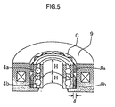
- the retainer member 9 is the retainer member coated with resin mold and formed into a cylinder for receiving electromagnets constituting the thrust bearing 3a of Fig. 7. Then, the touchdown bearing 4, i.e., the pair of roller bearings 4a and 4b disposed in the upper and lower stages are received in the inner circumferential portion of the retainer member 9.
- the annular gap G is formed between the inner circumferential surface of the cylindrical retainer member 9 and the outer races of the pair of roller bearings 4a and 4b, a pair of corrugated strip steel plates 8a and 8b that form the corrugated plate-like damper member are inserted into this annular gap G, and a strip-like metal thin plate 10a is inserted while being clamped by the upper corrugated strip steel plate 8a and the lower corrugated strip steel plate 8b.
- the corrugated strip steel plates 8a and 8b are, for instance, the corrugated strip steel plates as shown in Fig. 6.
- the pair of roller bearings 4a and 4b are depressed in the radial direction by the elasticity of the corrugated strip steel plates 8a and 8b and retained over the inner circumferential portion of the retainer member 9.
- the corrugated strip steel plates 8a and 8b are also retained in a predetermined position within the annular gap G by the elasticity thereof.
- the strip-like metal thin plate 10a is a means for preventing the positional offset of the corrugated plate-like damper member.
- the selection of the metal thin plate 10a and the determination of the width ⁇ of the annular gap relate to the thickness T of the metal thin plate 10a, the thickness t of the corrugated strip steel plates and the width ⁇ of the annular gap mutually.
- the movable amount of the corrugated portion of the corrugated strip steel plates i.e., the radial movable amount of the rotor is reduced, resulting in disability to obtain the necessary elastic force.
- the selection of the metal thin plate 10a and the determination of the width ⁇ of the annular gap are performed so that the sum (T+t) of the thickness T of the metal thin plate 10a and the thickness t of the corrugated strip steel plates is 0.8 to 1.3 times of the width ⁇ of the annular gap.
- the effect to prevent the positional offset of the corrugated plate-like damper member is further enhanced.
- the positional offset preventing means of the corrugated plate-like damper member is an annular convex portion 10b formed on the inner circumferential surface of a cylindrical retainer member 9.
- An annular gap G is divided into the upper and lower stages by this annular convex portion 10b.
- a corrugated strip steel plate 8b and a corrugated strip steel plate 8a are inserted into the lower annular gap and the upper annular gap, respectively. Accordingly, also in the second embodiment, the corrugated strip steel plates 8a and 8b are always held in a predetermined position of the annular gap G without fail.
- the height T of the annular convex portion and the width ⁇ of the annular gap are determined so that the sum (T+t) of the height T of the annular convex portion and the thickness t of the corrugated strip steel plates is 0.8 and 1.3 times of the width ⁇ of the annular gap.
- the effect to prevent the positional offset of the corrugated plate-like damper member is further enhanced.
- the positional offset preventing means of the corrugated plate-like damper member is an annular concave portion 10c formed in the inner circumferential surface of the cylindrical retainer member 9.
- a single corrugated strip steel plate 8c is inserted into this annular concave portion 10c. Accordingly, also in the third embodiment, the corrugated strip steel plate 8c is always held in a predetermined position of an annular gap G without fail.
- the depth T of the annular concave portion and the width ⁇ of the annular gap are determined so that the sum (T+t) of the depth T of the annular concave portion and the thickness t of the corrugated strip steel plate is 0.8 and 1.3 times of the width ⁇ of the annular gap.
- the effect to prevent the positional offset of the corrugated plate-like damper member is further enhanced.
- two corrugated plate-like damper members are used.
- the single wide corrugated plate-like damper member is used, thereby the cost is advantageously reduced.
- the sum (T+t) of the height of the metal thin plate, the height of the annular convex portion or the depth of the annular concave portion T and the thickness t of the corrugated strip steel plate is 0.8 to 1.3 times of the width ⁇ of the annular gap.
- the corrugated strip steel plates are buckled or aged due to the use for a long period of time, or the height becomes h'.
- the height h of the corrugated strip steel plates becomes half the length of 0.25 mm and h' becomes 0.125 mm.
- ⁇ ( ⁇ -t)/2 .
- the energy E applied to the cylindrical retainer member 9 upon the touchdown has a proportional relation with the product mf 2 of the second powered value f 2 of the frequency f and the mass m.
- the above-described energy E may be reduced one ninth theoretically by the corrugated plate-like damper member.
- the corrugated plate-like damper member since the pair of corrugated strip steel plates 8a and 8b and the metal thin plate 10a clamped by these plates have portions in contact with each other at the end faces in the axial direction, the corrugated plate-like damper member is prevented from serving as the spring. If so, there is a problem that the effect of the corrugated plate-like damper member for considerably reducing the energy E applied to the cylindrical retainer member 9 upon the touchdown would be degraded.
- FIG. 4 shows an embodiment in which a rectangular corrugated strip steel plate 8a without any cutaway portion, a rectangular corrugated strip steel plate 8b without any cutaway portion and a rectangular thin steel plate 10a with cutaway portions in the upper and lower side surfaces are used in combination.
- Fig. 4(B) shows an embodiment in which a rectangular corrugated strip steel plate 8a without any cutaway portion, a rectangular corrugated strip steel plate 8b without any cutaway portion and a rectangular thin steel plate 10a with cutaway portions in the upper and lower side surfaces are used in combination.
- FIG. 4(C) shows an embodiment in which a rectangular corrugated strip steel plate 8a with cutaway portions in the lower side surface, a rectangular corrugated strip steel plate 8b with cutaway portions in the upper side surface and a rectangular thin steel plate 10a without any cutaway portion are used in combination.
- Fig. 4(D) shows an embodiment in which a rectangular corrugated strip steel plate 8a with cutaway portions in the upper side surface, a rectangular corrugated strip steel plate 8b with cutaway portions in the lower side surface and a rectangular thin steel plate 10a without any cutaway portion are used in combination.
- Fig. 4(D) shows an embodiment in which a rectangular corrugated strip steel plate 8a with cutaway portions in the upper side surface, a rectangular corrugated strip steel plate 8b with cutaway portions in the lower side surface and a rectangular thin steel plate 10a without any cutaway portion are used in combination.
- Fig. 4(D) shows an embodiment in which a rectangular corrugated strip steel plate 8a with cutaway portions in the upper side surface,
- 4(E) shows an embodiment in which a rectangular corrugated strip steel plate 8a with cutaway portions in the upper and lower side surfaces, a rectangular corrugated strip steel plate 8b with cutaway portions in the upper and lower side surfaces and a rectangular thin steel plate 10a without any cutaway portion are used in combination.
- E t2 ⁇ (f 0 2 /2 ⁇ )(G 3 /9+G 4 )
- G 3 is the vibration level of the rotor upon the touchdown in the case where the contact portion of the corrugated plate-like damper member to the metal thin plate is one third of the non-contact portion
- G 4 is the vibration level at the rated rotational frequency of the rotor.
- the cylindrical retainer member 9 is the retainer member that receives electromagnets forming the thrust bearing 3a, molded of resin and formed into a cylindrical shape.
- this may be formed with another structure, for example, a structure integral with a stator column of the magnetic bearing apparatus.
- a magnetic bearing apparatus provided at least with a touchdown bearing and a pair of corrugated plate-like damper members inserted into an annular gap with a retainer member thereof and a vacuum pump provided with this, being provided with a positional offset preventing means of the corrugated plate-like damper member in the annular gap. Accordingly, since the corrugated plate-like damper members are held in a predetermined position without fail even if they are narrow corrugated strip steel plates, it is possible that the corrugated plate-like damper members are prevented from being offset to occur abnormal contact between the rotor and the touchdown bearing.
- the positional offset preventing means of the above corrugated plate-like damper member is simple in structure, it is possible to reduce the increase of the manufacture cost thereby as much as possible. Furthermore, there is no positional offset, and there is no unduly strong external force. Thus, the durability of the corrugated plate-like damper member per se is enhanced and the necessity to exchange the parts upon the overhaul is obviated.
Landscapes
- Engineering & Computer Science (AREA)
- General Engineering & Computer Science (AREA)
- Mechanical Engineering (AREA)
- Physics & Mathematics (AREA)
- Electromagnetism (AREA)
- Magnetic Bearings And Hydrostatic Bearings (AREA)
- Non-Positive Displacement Air Blowers (AREA)
- Structures Of Non-Positive Displacement Pumps (AREA)
- Support Of The Bearing (AREA)
- Vibration Prevention Devices (AREA)
- Springs (AREA)
Abstract
Description
Claims (6)
- A magnetic bearing apparatus provided at least with a rotor shaft, a radial magnetic bearing for supporting said rotor shaft in a radial direction, a thrust magnetic bearing for supporting said rotor shaft in an axial direction, a touchdown bearing composed of a pair of roller bearings arranged to surround a lower end portion of said rotor shaft, and a corrugated plate-like damper member inserted into an annular gap between said touchdown bearing and its retainer member, characterized by comprising a positional offset preventing means of said corrugated plate-like damper member provided in said annular gap.
- The magnetic bearing apparatus according to claim 1, characterized in that said corrugated plate-like damper member is composed of a pair of corrugated plate-like damper members and said positional offset preventing means is a metal thin plate interposed between said pair of corrugated plate-like damper members.
- The magnetic bearing apparatus according to claim 1, characterized in that said corrugated plate-like damper member is composed of a pair of corrugated plate-like damper members and said positional offset preventing means is an annular convex portion formed in an inner circumferential surface of said retainer member for separating said pair of corrugated plate-like damper members up and down.
- The magnetic bearing apparatus according to claim 1, characterized in that said positional offset preventing means is an annular concave portion formed in an inner circumferential surface of said retainer member for receiving said corrugated plate-like damper member.
- The magnetic bearing apparatus according to claim 2, 3 or 4, characterized in that a thickness of a metal thin plate, a sum (T+t) of a height of annular convex portion or a depth of an annular concave portion T and a thickness t of a corrugated strip steel plate is 0.8 to 1.3 times of a width δ of the annular gap.
- A vacuum pump provided with the magnetic bearing apparatus according to claim 1.
Applications Claiming Priority (5)
| Application Number | Priority Date | Filing Date | Title |
|---|---|---|---|
| JP9397099 | 1999-03-31 | ||
| JP9397099 | 1999-03-31 | ||
| JP2000087482A JP4426049B2 (en) | 1999-03-31 | 2000-03-27 | Magnetic bearing device and vacuum pump |
| JP2000087482 | 2000-03-27 | ||
| PCT/JP2000/002062 WO2000058639A1 (en) | 1999-03-31 | 2000-03-31 | Magnetic bearing device and vacuum pump |
Publications (3)
| Publication Number | Publication Date |
|---|---|
| EP1083349A1 true EP1083349A1 (en) | 2001-03-14 |
| EP1083349A4 EP1083349A4 (en) | 2002-06-26 |
| EP1083349B1 EP1083349B1 (en) | 2005-09-21 |
Family
ID=26435233
Family Applications (1)
| Application Number | Title | Priority Date | Filing Date |
|---|---|---|---|
| EP00913012A Expired - Lifetime EP1083349B1 (en) | 1999-03-31 | 2000-03-31 | Magnetic bearing device and vacuum pump |
Country Status (6)
| Country | Link |
|---|---|
| US (1) | US6617733B1 (en) |
| EP (1) | EP1083349B1 (en) |
| JP (1) | JP4426049B2 (en) |
| KR (1) | KR100784592B1 (en) |
| DE (1) | DE60022715T2 (en) |
| WO (1) | WO2000058639A1 (en) |
Cited By (12)
| Publication number | Priority date | Publication date | Assignee | Title |
|---|---|---|---|---|
| WO2007122044A1 (en) * | 2006-04-18 | 2007-11-01 | Siemens Aktiengesellschaft | Electrical machine with magnetic bearing and safety bearing |
| US7679245B2 (en) | 2001-09-17 | 2010-03-16 | Beacon Power Corporation | Repulsive lift systems, flywheel energy storage systems utilizing such systems and methods related thereto |
| RU2440518C1 (en) * | 2010-08-27 | 2012-01-20 | Государственное образовательное учреждение высшего профессионального образования "Уфимский государственный нефтяной технический университет" | Vibration-isolating rotor suspension of machines and equipment |
| DE102010035183A1 (en) | 2010-08-24 | 2012-03-01 | Schaeffler Technologies Gmbh & Co. Kg | Safety bearing for a magnetic bearing |
| WO2012152541A1 (en) * | 2011-05-12 | 2012-11-15 | Schaeffler Technologies AG & Co. KG | Bearing arrangement with a back-up bearing, in particular for mounting a rapidly rotating shaft |
| WO2012152539A1 (en) * | 2011-05-12 | 2012-11-15 | Schaeffler Technologies AG & Co. KG | Bearing arrangement with a back-up bearing, in particular for mounting the rapidly rotating shaft of a compressor |
| JP2013525712A (en) * | 2010-05-06 | 2013-06-20 | シェフラー テクノロジーズ アクチエンゲゼルシャフト ウント コンパニー コマンディートゲゼルシャフト | Rolling bearing device with hydraulic shock absorber |
| US8715835B2 (en) | 2009-02-26 | 2014-05-06 | John Crane Uk Limited | Tolerance strips |
| EP2784326A1 (en) * | 2013-03-25 | 2014-10-01 | Skf Magnetic Mechatronics | Compact turbomachine with magnetic bearings and auxiliary bearings |
| US8851829B2 (en) | 2007-01-29 | 2014-10-07 | Edwards Limited | Vacuum pump |
| WO2014194899A1 (en) * | 2013-06-03 | 2014-12-11 | Schaeffler Technologies Gmbh & Co. Kg | Bearing assembly having a back-up bearing |
| US20150275911A1 (en) * | 2014-03-25 | 2015-10-01 | Société de Mécanique Magnétique | Compact turbomachine with magnetic bearings and auxiliary bearings |
Families Citing this family (46)
| Publication number | Priority date | Publication date | Assignee | Title |
|---|---|---|---|---|
| JP3892674B2 (en) | 2001-02-23 | 2007-03-14 | 株式会社東芝 | Rotating anode X-ray tube |
| EP1619400B1 (en) * | 2004-07-20 | 2009-11-11 | VARIAN S.p.A. | Annular support for rolling bearings |
| DE602005019775D1 (en) * | 2004-12-01 | 2010-04-15 | Jtekt Corp | CONTACT BEARING |
| JP2006226268A (en) * | 2005-02-21 | 2006-08-31 | Mitsubishi Heavy Ind Ltd | Bearing structure of vacuum pump and vacuum pump using it |
| DE102005025261A1 (en) * | 2005-06-02 | 2006-12-14 | Leybold Vacuum Gmbh | Vacuum pump has housing containing rolling bearing with stator ring and sprung heat bridging element located between housing and ring for rotory shaft thermally connecting the two for better heat conduction |
| US20070110351A1 (en) * | 2005-11-16 | 2007-05-17 | Honeywell International, Inc. | Centering mechanisms for turbocharger bearings |
| DE102006040816A1 (en) * | 2006-08-31 | 2008-03-06 | Schaeffler Kg | Roller bearing for e.g. motor, has rolling body, inner ring and outer ring exhibiting circular magnetization with alternative polarized sections, where rings effect forced rotation of another rolling body during rotation of inner ring |
| KR100792792B1 (en) | 2006-10-26 | 2008-01-14 | 한국기계연구원 | Magnetic Bearings with Double Dampers |
| DE102007003470A1 (en) * | 2007-01-24 | 2008-07-31 | Schaeffler Kg | Bearing unit with adjustable friction torque to provide a braking function |
| CN100523535C (en) * | 2007-12-24 | 2009-08-05 | 南京航空航天大学 | Centripetal protection bearing for magnetic levitation bearing system |
| RU2010142965A (en) | 2008-04-17 | 2012-05-27 | Синкрони, Инк. (US) | HIGH SPEED MOTOR WITH PERMANENT MAGNET AND GENERATOR WITH METAL ROTOR WITH LOW LEVEL |
| CA2721818A1 (en) | 2008-04-18 | 2009-11-19 | Synchrony, Inc. | Magnetic thrust bearing with integrated electronics |
| US8083500B1 (en) * | 2008-06-11 | 2011-12-27 | AquaMotion, Inc. | Motor pump |
| FR2934339B1 (en) * | 2008-07-25 | 2010-09-03 | Mecanique Magnetique Sa | INSENSITIVE EMERGENCY BEARING WITH AXIAL LOAD |
| IT1391855B1 (en) | 2008-09-04 | 2012-01-27 | Indesit Co Spa | METHOD AND DEVICE FOR CONVEYING WASHING AGENTS INTO A WASHING MACHINE |
| JP5359303B2 (en) * | 2009-01-20 | 2013-12-04 | 株式会社ジェイテクト | Rolling bearing device |
| US9583991B2 (en) | 2009-06-24 | 2017-02-28 | Synchrony, Inc. | Systems, devices, and/or methods for managing magnetic bearings |
| WO2011044428A2 (en) * | 2009-10-09 | 2011-04-14 | Dresser-Rand Company | Auxiliary bearing system for magnetically supported rotor system |
| US8987959B2 (en) | 2010-06-23 | 2015-03-24 | Dresser-Rand Company | Split magnetic thrust bearing |
| EP2659277B8 (en) | 2010-12-30 | 2018-05-23 | Dresser-Rand Company | Method for on-line detection of resistance-to-ground faults in active magnetic bearing systems |
| US8994237B2 (en) | 2010-12-30 | 2015-03-31 | Dresser-Rand Company | Method for on-line detection of liquid and potential for the occurrence of resistance to ground faults in active magnetic bearing systems |
| RU2468268C2 (en) * | 2011-02-25 | 2012-11-27 | Государственное образовательное учреждение высшего профессионального образования "Тольяттинский государственный университет" | Dynamic vibration damper |
| US9551349B2 (en) | 2011-04-08 | 2017-01-24 | Dresser-Rand Company | Circulating dielectric oil cooling system for canned bearings and canned electronics |
| RU2466313C1 (en) * | 2011-04-18 | 2012-11-10 | Государственное образовательное учреждение высшего профессионального образования "Тольяттинский государственный университет" | Vibration-damping support |
| EP2715167B1 (en) | 2011-05-27 | 2017-08-30 | Dresser-Rand Company | Segmented coast-down bearing for magnetic bearing systems |
| US8851756B2 (en) | 2011-06-29 | 2014-10-07 | Dresser-Rand Company | Whirl inhibiting coast-down bearing for magnetic bearing systems |
| JP5919745B2 (en) * | 2011-11-15 | 2016-05-18 | 株式会社島津製作所 | Vacuum pump |
| RU2486384C1 (en) * | 2012-01-11 | 2013-06-27 | Федеральное государственное бюджетное образовательное учреждение высшего профессионального образования "Самарский государственный университет путей сообщения" (СамГУПС) | Elastic damping support of rotor |
| KR101408060B1 (en) * | 2012-06-19 | 2014-06-18 | 한국기계연구원 | complex magnetic bearing combined with auxiliary bearing |
| EP2808551B1 (en) * | 2013-05-30 | 2020-01-08 | Nuovo Pignone S.r.l. | Rotating machine with at least one active magnetic bearing and auxiliary rolling bearings |
| EP2829756B1 (en) * | 2013-07-26 | 2016-06-29 | SKF Magnetic Mechatronics S.A.S. | Auxiliary bearing of the ball bearing type for a magnetically suspended rotor system |
| DE102013215892A1 (en) * | 2013-08-12 | 2015-02-12 | Schaeffler Technologies Gmbh & Co. Kg | Bearing with a double row polygon bearing |
| JP5996100B2 (en) * | 2013-11-12 | 2016-09-21 | 株式会社キッツ | Antistatic function valve and its mounting jig |
| FR3016667B1 (en) * | 2014-01-22 | 2016-08-26 | Ntn-Snr Roulements | ROLLING ASSEMBLY COMPRISING A BEARING UNIT AND A MECHANICAL PART. |
| CN103883622A (en) * | 2014-03-05 | 2014-06-25 | 北京交通大学 | Magnetic liquid cylindrical roller bearing |
| DE102015100048B4 (en) * | 2015-01-06 | 2018-02-08 | Pfeiffer Vacuum Gmbh | Arrangement for supporting a shaft of a vacuum pump |
| DE102016220196B4 (en) | 2015-11-18 | 2021-12-09 | Schaeffler Technologies AG & Co. KG | Catch storage system |
| DE102015014833B3 (en) * | 2015-11-18 | 2017-02-23 | Schaeffler Technologies AG & Co. KG | Safety bearing system |
| RU170555U1 (en) * | 2016-06-06 | 2017-04-28 | Федеральное государственное бюджетное образовательное учреждение высшего образования "Самарский государственный университет путей сообщения" (СамГУПС) | Combined vibration isolator |
| DE102016214505A1 (en) | 2016-08-05 | 2018-02-08 | Robert Bosch Gmbh | Compensation sleeve for a bearing device, bearing device with a compensating sleeve and method for mounting a compensating sleeve |
| EP3327302B1 (en) * | 2016-11-28 | 2019-11-13 | Skf Magnetic Mechatronics | Landing bearing assembly and rotary machine equipped with such an assembly |
| US10982730B2 (en) | 2019-03-04 | 2021-04-20 | Saint- Augustin Canada Electric Inc. | Flywheel systems and related methods |
| RU194394U1 (en) * | 2019-03-15 | 2019-12-09 | Федеральное государственное бюджетное образовательное учреждение высшего образования "Самарский государственный университет путей сообщения" (СамГУПС) | ELASTIC DAMPING ROTOR SUPPORT |
| JP7319520B2 (en) | 2019-03-27 | 2023-08-02 | ダイキン工業株式会社 | bearing structure |
| CN110259824B (en) * | 2019-06-05 | 2020-06-19 | 清华大学 | Protective bearing assembly of magnetic bearing |
| JP7463332B2 (en) | 2021-11-16 | 2024-04-08 | エドワーズ株式会社 | Vacuum pump, vacuum pump bearing protection structure, and vacuum pump rotor |
Family Cites Families (18)
| Publication number | Priority date | Publication date | Assignee | Title |
|---|---|---|---|---|
| DE934447C (en) | 1953-04-12 | 1955-10-20 | Bayerische Motoren Werke Ag | Securing for ball bearing seats using a resilient mounting ring |
| US4274683A (en) | 1978-12-29 | 1981-06-23 | Mechanical Technology Incorporated | Support element for compliant hydrodynamic journal bearings |
| CH658499A5 (en) * | 1982-05-26 | 1986-11-14 | Bbc Brown Boveri & Cie | Resilient supporting device for shaft bearings of high-speed rotors, in particular those of turbo machines |
| DE3367658D1 (en) * | 1982-05-26 | 1987-01-02 | Bbc Brown Boveri & Cie | Resilient bearing support for high-speed rotors, particularly for turbo machines |
| JPS61285140A (en) * | 1985-06-12 | 1986-12-15 | Fujitsu Ten Ltd | Constant speed running device for vehicle |
| FR2614375B1 (en) * | 1987-04-23 | 1992-07-31 | Mecanique Magnetique Sa | RADIAL AUXILIARY BEARING FOR MAGNETIC SUSPENSION |
| JPH0526237A (en) * | 1991-07-26 | 1993-02-02 | Ntn Corp | Touchdown bearing of magnetic bearing device |
| US5462402A (en) * | 1994-02-22 | 1995-10-31 | Rosen Motors, L.P. | Flywheel energy storage system with integral molecular pump |
| US5714818A (en) | 1994-10-18 | 1998-02-03 | Barber-Colman Company | Backup bearing for magnetic bearings |
| JPH09236096A (en) * | 1996-02-29 | 1997-09-09 | Nippon Seiko Kk | Rotor shaft support structure of magnetic levitation turbo molecular pump |
| US5708312A (en) * | 1996-11-19 | 1998-01-13 | Rosen Motors, L.P. | Magnetic bearing system including a control system for a flywheel and method for operating same |
| US6262505B1 (en) * | 1997-03-26 | 2001-07-17 | Satcon Technology Corporation | Flywheel power supply having axial magnetic bearing for frictionless rotation |
| US5739609A (en) * | 1997-04-09 | 1998-04-14 | Koyo Seiko Co., Ltd. | Magnetic bearing apparatus |
| US6213737B1 (en) * | 1997-04-18 | 2001-04-10 | Ebara Corporation | Damper device and turbomolecular pump with damper device |
| JP3672416B2 (en) * | 1997-06-27 | 2005-07-20 | 株式会社荏原製作所 | Spin processing equipment |
| JPH1182522A (en) * | 1997-09-17 | 1999-03-26 | Ntn Corp | Touchdown bearing for magnetic bearing device |
| JP2000183436A (en) * | 1998-12-18 | 2000-06-30 | Komatsu Ltd | Excimer laser device |
| JP2000230550A (en) * | 1999-02-09 | 2000-08-22 | Seiko Seiki Co Ltd | Magnetic bearing device |
-
2000
- 2000-03-27 JP JP2000087482A patent/JP4426049B2/en not_active Expired - Lifetime
- 2000-03-31 WO PCT/JP2000/002062 patent/WO2000058639A1/en not_active Ceased
- 2000-03-31 DE DE60022715T patent/DE60022715T2/en not_active Expired - Lifetime
- 2000-03-31 US US09/700,640 patent/US6617733B1/en not_active Expired - Lifetime
- 2000-03-31 EP EP00913012A patent/EP1083349B1/en not_active Expired - Lifetime
- 2000-03-31 KR KR1020007013551A patent/KR100784592B1/en not_active Expired - Lifetime
Cited By (20)
| Publication number | Priority date | Publication date | Assignee | Title |
|---|---|---|---|---|
| US7679245B2 (en) | 2001-09-17 | 2010-03-16 | Beacon Power Corporation | Repulsive lift systems, flywheel energy storage systems utilizing such systems and methods related thereto |
| US7952247B2 (en) | 2006-04-18 | 2011-05-31 | Siemens Aktiengesellschaft | Electrical machine with magnetic bearing and safety bearing |
| CN101427038B (en) * | 2006-04-18 | 2011-07-27 | 西门子公司 | Electrical machine with magnetic bearing and safety bearing |
| WO2007122044A1 (en) * | 2006-04-18 | 2007-11-01 | Siemens Aktiengesellschaft | Electrical machine with magnetic bearing and safety bearing |
| US9759256B2 (en) | 2007-01-29 | 2017-09-12 | Edwards Limited | Vacuum pump |
| US8851829B2 (en) | 2007-01-29 | 2014-10-07 | Edwards Limited | Vacuum pump |
| US8715835B2 (en) | 2009-02-26 | 2014-05-06 | John Crane Uk Limited | Tolerance strips |
| JP2013525712A (en) * | 2010-05-06 | 2013-06-20 | シェフラー テクノロジーズ アクチエンゲゼルシャフト ウント コンパニー コマンディートゲゼルシャフト | Rolling bearing device with hydraulic shock absorber |
| DE102010035183A1 (en) | 2010-08-24 | 2012-03-01 | Schaeffler Technologies Gmbh & Co. Kg | Safety bearing for a magnetic bearing |
| WO2012025292A1 (en) | 2010-08-24 | 2012-03-01 | Schaeffler Technologies Gmbh & Co. Kg | Safety bearing for a magnetic bearing |
| RU2440518C1 (en) * | 2010-08-27 | 2012-01-20 | Государственное образовательное учреждение высшего профессионального образования "Уфимский государственный нефтяной технический университет" | Vibration-isolating rotor suspension of machines and equipment |
| CN103534500A (en) * | 2011-05-12 | 2014-01-22 | 谢夫勒科技股份两合公司 | Bearing systems with back-up bearings, especially for supporting rapidly rotating shafts |
| WO2012152539A1 (en) * | 2011-05-12 | 2012-11-15 | Schaeffler Technologies AG & Co. KG | Bearing arrangement with a back-up bearing, in particular for mounting the rapidly rotating shaft of a compressor |
| CN103534500B (en) * | 2011-05-12 | 2016-03-30 | 舍弗勒技术股份两合公司 | Bearing system with a back-up bearing, in particular for mounting a rapidly rotating shaft |
| WO2012152541A1 (en) * | 2011-05-12 | 2012-11-15 | Schaeffler Technologies AG & Co. KG | Bearing arrangement with a back-up bearing, in particular for mounting a rapidly rotating shaft |
| EP2784326A1 (en) * | 2013-03-25 | 2014-10-01 | Skf Magnetic Mechatronics | Compact turbomachine with magnetic bearings and auxiliary bearings |
| WO2014194899A1 (en) * | 2013-06-03 | 2014-12-11 | Schaeffler Technologies Gmbh & Co. Kg | Bearing assembly having a back-up bearing |
| US9841053B2 (en) | 2013-06-03 | 2017-12-12 | Schaeffler Technologies AG & Co. KG | Bearing assembly having a back-up bearing |
| US20150275911A1 (en) * | 2014-03-25 | 2015-10-01 | Société de Mécanique Magnétique | Compact turbomachine with magnetic bearings and auxiliary bearings |
| US10208759B2 (en) * | 2014-03-25 | 2019-02-19 | Skf Magnetic Mechatronics | Compact turbomachine with magnetic bearings and auxiliary bearings |
Also Published As
| Publication number | Publication date |
|---|---|
| DE60022715T2 (en) | 2006-04-27 |
| US6617733B1 (en) | 2003-09-09 |
| JP2000346068A (en) | 2000-12-12 |
| JP4426049B2 (en) | 2010-03-03 |
| KR20010025114A (en) | 2001-03-26 |
| KR100784592B1 (en) | 2007-12-11 |
| EP1083349B1 (en) | 2005-09-21 |
| DE60022715D1 (en) | 2006-02-02 |
| EP1083349A4 (en) | 2002-06-26 |
| WO2000058639A1 (en) | 2000-10-05 |
Similar Documents
| Publication | Publication Date | Title |
|---|---|---|
| EP1083349B1 (en) | Magnetic bearing device and vacuum pump | |
| EP0462739B1 (en) | Bearing isolator | |
| JP3138435B2 (en) | Rotational speed damper | |
| JP2000314451A (en) | Rotational speed damper | |
| JP5304524B2 (en) | Inner and outer rings and ball bearings | |
| US20140072253A1 (en) | Bearing arrangement with a back-up bearing, in particular for mounting the rapidly rotating shaft of a compressor | |
| CN102804554A (en) | Suspension structures | |
| EP0473307B1 (en) | Bearing isolator | |
| JPH01146013U (en) | ||
| WO2020059695A1 (en) | Bearing device | |
| JPH08319942A (en) | Double-headed swash plate compressor | |
| JPH06307455A (en) | Linear ball bearing | |
| JPS6152417A (en) | Rotary attenuation type roll bearing | |
| CN120659927A (en) | motor | |
| JP2011094727A (en) | Creep prevention device for rolling bearing | |
| JP3632262B2 (en) | Thrust roller bearing | |
| JP2000081042A (en) | Cylindrical roller bearing | |
| JP3807025B2 (en) | bearing | |
| JPH0198712A (en) | Cylindrical roller bearing | |
| JPH0657768U (en) | Bearing device for steering column | |
| JP2743458B2 (en) | Rolling shaft support device with rolling bearing support sleeve, sleeved rolling bearing and sleeved rolling bearing | |
| JP2004011667A (en) | Roller bearing and cage for the same | |
| JP2001082584A (en) | Pulley unit | |
| JP2597520Y2 (en) | Anti-creep device for rolling bearings | |
| JPH07208461A (en) | Bearing device for steering column |
Legal Events
| Date | Code | Title | Description |
|---|---|---|---|
| PUAI | Public reference made under article 153(3) epc to a published international application that has entered the european phase |
Free format text: ORIGINAL CODE: 0009012 |
|
| AK | Designated contracting states |
Kind code of ref document: A1 Designated state(s): AT BE CH CY DE DK ES FI FR GB GR IE IT LI LU MC NL PT SE |
|
| 17P | Request for examination filed |
Effective date: 20010319 |
|
| RAP1 | Party data changed (applicant data changed or rights of an application transferred) |
Owner name: SEIKO INSTRUMENTS INC. |
|
| A4 | Supplementary search report drawn up and despatched |
Effective date: 20020513 |
|
| AK | Designated contracting states |
Kind code of ref document: A4 Designated state(s): AT BE CH CY DE DK ES FI FR GB GR IE IT LI LU MC NL PT SE |
|
| RIC1 | Information provided on ipc code assigned before grant |
Free format text: 7F 16C 32/04 A, 7F 04D 29/04 B, 7F 04D 19/04 B, 7F 16C 39/06 B, 7F 16C 27/04 B |
|
| RBV | Designated contracting states (corrected) |
Designated state(s): CH DE FR GB IT LI |
|
| 17Q | First examination report despatched |
Effective date: 20040603 |
|
| RAP1 | Party data changed (applicant data changed or rights of an application transferred) |
Owner name: BOC EDWARDS JAPAN LIMITED |
|
| GRAP | Despatch of communication of intention to grant a patent |
Free format text: ORIGINAL CODE: EPIDOSNIGR1 |
|
| GRAS | Grant fee paid |
Free format text: ORIGINAL CODE: EPIDOSNIGR3 |
|
| GRAA | (expected) grant |
Free format text: ORIGINAL CODE: 0009210 |
|
| AK | Designated contracting states |
Kind code of ref document: B1 Designated state(s): CH DE FR GB IT LI |
|
| PG25 | Lapsed in a contracting state [announced via postgrant information from national office to epo] |
Ref country code: IT Free format text: LAPSE BECAUSE OF FAILURE TO SUBMIT A TRANSLATION OF THE DESCRIPTION OR TO PAY THE FEE WITHIN THE PRESCRIBED TIME-LIMIT;WARNING: LAPSES OF ITALIAN PATENTS WITH EFFECTIVE DATE BEFORE 2007 MAY HAVE OCCURRED AT ANY TIME BEFORE 2007. THE CORRECT EFFECTIVE DATE MAY BE DIFFERENT FROM THE ONE RECORDED. Effective date: 20050921 Ref country code: CH Free format text: LAPSE BECAUSE OF FAILURE TO SUBMIT A TRANSLATION OF THE DESCRIPTION OR TO PAY THE FEE WITHIN THE PRESCRIBED TIME-LIMIT Effective date: 20050921 Ref country code: LI Free format text: LAPSE BECAUSE OF FAILURE TO SUBMIT A TRANSLATION OF THE DESCRIPTION OR TO PAY THE FEE WITHIN THE PRESCRIBED TIME-LIMIT Effective date: 20050921 |
|
| REG | Reference to a national code |
Ref country code: GB Ref legal event code: FG4D |
|
| REG | Reference to a national code |
Ref country code: CH Ref legal event code: EP |
|
| REF | Corresponds to: |
Ref document number: 60022715 Country of ref document: DE Date of ref document: 20051027 Kind code of ref document: P |
|
| REF | Corresponds to: |
Ref document number: 60022715 Country of ref document: DE Date of ref document: 20060202 Kind code of ref document: P |
|
| REG | Reference to a national code |
Ref country code: CH Ref legal event code: PL |
|
| ET | Fr: translation filed | ||
| PLBE | No opposition filed within time limit |
Free format text: ORIGINAL CODE: 0009261 |
|
| STAA | Information on the status of an ep patent application or granted ep patent |
Free format text: STATUS: NO OPPOSITION FILED WITHIN TIME LIMIT |
|
| 26N | No opposition filed |
Effective date: 20060622 |
|
| REG | Reference to a national code |
Ref country code: FR Ref legal event code: CA Ref country code: FR Ref legal event code: CD |
|
| REG | Reference to a national code |
Ref country code: GB Ref legal event code: 732E |
|
| REG | Reference to a national code |
Ref country code: FR Ref legal event code: PLFP Year of fee payment: 17 |
|
| REG | Reference to a national code |
Ref country code: FR Ref legal event code: PLFP Year of fee payment: 18 |
|
| REG | Reference to a national code |
Ref country code: FR Ref legal event code: PLFP Year of fee payment: 19 |
|
| PGFP | Annual fee paid to national office [announced via postgrant information from national office to epo] |
Ref country code: DE Payment date: 20190319 Year of fee payment: 20 Ref country code: GB Payment date: 20190327 Year of fee payment: 20 |
|
| PGFP | Annual fee paid to national office [announced via postgrant information from national office to epo] |
Ref country code: FR Payment date: 20190213 Year of fee payment: 20 |
|
| REG | Reference to a national code |
Ref country code: DE Ref legal event code: R071 Ref document number: 60022715 Country of ref document: DE |
|
| REG | Reference to a national code |
Ref country code: GB Ref legal event code: PE20 Expiry date: 20200330 |
|
| PG25 | Lapsed in a contracting state [announced via postgrant information from national office to epo] |
Ref country code: GB Free format text: LAPSE BECAUSE OF EXPIRATION OF PROTECTION Effective date: 20200330 |