EP1083311A2 - Engine with a supercharger - Google Patents
Engine with a supercharger Download PDFInfo
- Publication number
- EP1083311A2 EP1083311A2 EP00119783A EP00119783A EP1083311A2 EP 1083311 A2 EP1083311 A2 EP 1083311A2 EP 00119783 A EP00119783 A EP 00119783A EP 00119783 A EP00119783 A EP 00119783A EP 1083311 A2 EP1083311 A2 EP 1083311A2
- Authority
- EP
- European Patent Office
- Prior art keywords
- engine
- supercharger
- set forth
- cylinder head
- drive shaft
- Prior art date
- Legal status (The legal status is an assumption and is not a legal conclusion. Google has not performed a legal analysis and makes no representation as to the accuracy of the status listed.)
- Granted
Links
Images


Classifications
-
- F—MECHANICAL ENGINEERING; LIGHTING; HEATING; WEAPONS; BLASTING
- F02—COMBUSTION ENGINES; HOT-GAS OR COMBUSTION-PRODUCT ENGINE PLANTS
- F02B—INTERNAL-COMBUSTION PISTON ENGINES; COMBUSTION ENGINES IN GENERAL
- F02B67/00—Engines characterised by the arrangement of auxiliary apparatus not being otherwise provided for, e.g. the apparatus having different functions; Driving auxiliary apparatus from engines, not otherwise provided for
- F02B67/10—Engines characterised by the arrangement of auxiliary apparatus not being otherwise provided for, e.g. the apparatus having different functions; Driving auxiliary apparatus from engines, not otherwise provided for of charging or scavenging apparatus
Definitions
- the supercharger is a device in which using an air compressor driven by engine power, pressure of intake air drawn in the cylinder is raised higher than the atmospheric pressure, thereby increasing weight of the air in the cylinder to increase output of the engine.
- the supercharger is disposed on one side of the cylinder block because of its drive system or size, and in a straight type four cylinder engine, a balancer for balancing the moment of inertia of reciprocating mass is disposed in the cylinder block or in an oil pan.
- fresh air is forced into the exhaust system by an independent air pump to raise the temperature of the catalyst highly enough to activate the catalyst.
- the invention of claim 1 is characterized by an engine, wherein a Roots type air compressor driven by engine power is mounted on the top of a cylinder head.
- the invention of claim 2 is characterized by the engine of the invention of claim 1, wherein a balancer is fitted to a drive shaft of said air compressor.
- the invention of claim 3 is characterized by the engine of the invention of claim 1 or 2, wherein part of supercharged air from said compressor is inducted into exhaust ports through a passage in the cylinder head.
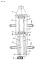
- FIGs. 1-3 show one embodiment of an engine with a supercharger of this invention.
- Fig. 1 is a sectional view around the cylinder head;
- Fig. 2 a side view illustrating the interior of the engine of Fig. 1;
- Fig. 3 a plan view of the supercharger as seen in the direction A of Fig. 2.
- the engine according to this invention is a straight type four cylinder four-stroke engine.
- a cylinder head 1 is formed with intake ports 2 and exhaust ports 3, and the intake port 2 and the exhaust port 3 are provided with intake valves 4 and exhaust valves 5, respectively.
- To the cylinder head 1 is connected at the top a head cover 6, inside of which is formed a valve drive chamber 7; within the valve drive chamber 7 are disposed an intake cam shaft and an exhaust cam shaft (not shown); and the intake valves 5 and the exhaust valves 5 are adapted to be opened and closed by cams 9, 10 provided on the respective cam shafts.
- a case body 12 of a supercharger 11 is fixed to the cylinder head 1 through bosses 12a and bolts 12b.
- Numeral 30 designates an injector.
- the supercharger 11 is a Roots type air compressor driven by the engine and provided in a housing 13 with two rotors 14, 14' each rotated in the opposite directions for compression action.
- rotors 14, 14' are coupled a drive shaft 16 and a driven shaft 17 supported on bearings 15 for rotation, which shafts are engaged with each other through gears 16a, 17a.
- a drive pulley 19 is coupled to one end of the driven shaft 16 through a belt 20.
- To the housing 13 is connected at one side an air intake 21.
- balancers 22, 22' of a semicircular cross section.
Landscapes
- Engineering & Computer Science (AREA)
- Chemical & Material Sciences (AREA)
- Combustion & Propulsion (AREA)
- Mechanical Engineering (AREA)
- General Engineering & Computer Science (AREA)
- Supercharger (AREA)
- Valve-Gear Or Valve Arrangements (AREA)
Abstract
Description
Claims (10)
Applications Claiming Priority (2)
| Application Number | Priority Date | Filing Date | Title |
|---|---|---|---|
| JP25592099A JP2001082160A (en) | 1999-09-09 | 1999-09-09 | Engine with supercharger |
| JP25592099 | 1999-09-09 |
Publications (3)
| Publication Number | Publication Date |
|---|---|
| EP1083311A2 true EP1083311A2 (en) | 2001-03-14 |
| EP1083311A3 EP1083311A3 (en) | 2002-04-10 |
| EP1083311B1 EP1083311B1 (en) | 2006-07-26 |
Family
ID=17285412
Family Applications (1)
| Application Number | Title | Priority Date | Filing Date |
|---|---|---|---|
| EP00119783A Expired - Lifetime EP1083311B1 (en) | 1999-09-09 | 2000-09-11 | Engine with a supercharger |
Country Status (4)
| Country | Link |
|---|---|
| US (1) | US6453890B1 (en) |
| EP (1) | EP1083311B1 (en) |
| JP (1) | JP2001082160A (en) |
| DE (1) | DE60029525D1 (en) |
Cited By (1)
| Publication number | Priority date | Publication date | Assignee | Title |
|---|---|---|---|---|
| EP3963188A4 (en) * | 2019-06-06 | 2022-06-15 | Magna International Inc | Charged serial hybrid combustion engine |
Families Citing this family (12)
| Publication number | Priority date | Publication date | Assignee | Title |
|---|---|---|---|---|
| AU2003241828A1 (en) | 2003-05-28 | 2005-01-21 | Dentsu Inc. | Contact point navigation system and method, recording medium on which the method is recorded, and transmission medium for transmitting the method |
| JP4357881B2 (en) | 2003-06-12 | 2009-11-04 | ヤマハ発動機株式会社 | Small ship |
| US6923166B2 (en) * | 2003-09-30 | 2005-08-02 | Trilogy Motorsports, Llc | Supercharging assembly for an internal combustion engine of a motor vehicle |
| KR100579265B1 (en) * | 2003-12-24 | 2006-05-11 | 현대자동차주식회사 | Vehicle engine intake |
| JP2006002633A (en) | 2004-06-16 | 2006-01-05 | Yamaha Marine Co Ltd | Water jet propulsion boat |
| JP2006037730A (en) | 2004-07-22 | 2006-02-09 | Yamaha Marine Co Ltd | Intake device for supercharged engine |
| JP2006083713A (en) | 2004-09-14 | 2006-03-30 | Yamaha Marine Co Ltd | Lubricating structure of supercharger |
| US20060157036A1 (en) * | 2005-01-18 | 2006-07-20 | Ekm Engineering, Inc. | Positive displacement supercharging apparatus for use in an in-line internal combustion engine and its method of formation |
| JP2007062432A (en) | 2005-08-29 | 2007-03-15 | Yamaha Marine Co Ltd | Small planing boat |
| JP4614853B2 (en) | 2005-09-26 | 2011-01-19 | ヤマハ発動機株式会社 | Turbocharger mounting structure |
| US8464696B2 (en) * | 2010-05-17 | 2013-06-18 | Ford Global Technologies, Llc | Supercharged engine system |
| US8925528B2 (en) * | 2012-06-26 | 2015-01-06 | Ford Global Technologies, Llc | Engine balancing supercharger |
Family Cites Families (18)
| Publication number | Priority date | Publication date | Assignee | Title |
|---|---|---|---|---|
| GB167764A (en) | 1920-08-10 | |||
| GB534161A (en) * | 1939-01-03 | 1941-02-28 | Milo Ab | Improvements in or relating to internal combustion engines of the four-stroke cycle type |
| FR2378179A1 (en) | 1977-01-25 | 1978-08-18 | Chrysler France | Balancing of in line four cylinder IC engine - uses three shafts, two driven from camshaft and third having gear wheel engaging single driven shaft to rotate in opposite direction |
| FR2512496A1 (en) * | 1981-09-10 | 1983-03-11 | Semt | METHOD FOR THE AMENAGEMENT OF THE OPERATING CONDITIONS OF AN INTERNAL COMBUSTION ENGINE AND A MOTOR THUS DONE |
| DE3817318C2 (en) | 1988-05-20 | 1997-05-28 | Mueller Alander Gerd Dipl Ing | Reciprocating internal combustion engine with at least one rotary piston supercharger type |
| US4944278A (en) | 1989-04-14 | 1990-07-31 | Eaton Corporation | Torsion damping mechanism for a supercharger |
| US5101794A (en) * | 1991-07-22 | 1992-04-07 | Blaricom Terry M Van | Internal combustion engine |
| JP3357385B2 (en) * | 1991-08-27 | 2002-12-16 | マツダ株式会社 | Engine with turbocharger |
| DE4232044C2 (en) * | 1991-09-26 | 1998-01-29 | Mazda Motor | Internal combustion engine with spark ignition |
| US5179921A (en) | 1992-01-30 | 1993-01-19 | Vincent Figliuzzi | Integrated engine and compressor device |
| US5535643A (en) * | 1993-11-12 | 1996-07-16 | General Motors Corporation | Anti-rattle engine balancer which drives associated oil pump |
| JP3421731B2 (en) * | 1994-05-31 | 2003-06-30 | ヤマハ発動機株式会社 | Engine intake control device |
| JPH08319839A (en) * | 1995-05-25 | 1996-12-03 | Tochigi Fuji Ind Co Ltd | Supercharger |
| JP3346109B2 (en) * | 1995-07-31 | 2002-11-18 | ヤマハ発動機株式会社 | Internal combustion engine |
| JP3553217B2 (en) * | 1995-07-17 | 2004-08-11 | ヤマハ発動機株式会社 | 4 cycle engine |
| JP3362162B2 (en) * | 1995-12-28 | 2003-01-07 | ヤマハ発動機株式会社 | V-type engine with supercharger |
| US5791309A (en) * | 1996-02-06 | 1998-08-11 | Honda Giken Kogyo Kabushiki Kaisha | Balancer shaft supporting structure in engine |
| US6029637A (en) * | 1998-12-16 | 2000-02-29 | General Motors Corporation | Induction assembly for supercharged internal combustion engine |
-
1999
- 1999-09-09 JP JP25592099A patent/JP2001082160A/en active Pending
-
2000
- 2000-08-25 US US09/648,835 patent/US6453890B1/en not_active Expired - Fee Related
- 2000-09-11 DE DE60029525T patent/DE60029525D1/en not_active Expired - Lifetime
- 2000-09-11 EP EP00119783A patent/EP1083311B1/en not_active Expired - Lifetime
Cited By (1)
| Publication number | Priority date | Publication date | Assignee | Title |
|---|---|---|---|---|
| EP3963188A4 (en) * | 2019-06-06 | 2022-06-15 | Magna International Inc | Charged serial hybrid combustion engine |
Also Published As
| Publication number | Publication date |
|---|---|
| DE60029525D1 (en) | 2006-09-07 |
| JP2001082160A (en) | 2001-03-27 |
| EP1083311A3 (en) | 2002-04-10 |
| US6453890B1 (en) | 2002-09-24 |
| EP1083311B1 (en) | 2006-07-26 |
Similar Documents
| Publication | Publication Date | Title |
|---|---|---|
| RU1806281C (en) | Multicylinder diesel low compression ratio engine | |
| JP3362162B2 (en) | V-type engine with supercharger | |
| EP1179676A1 (en) | In-cylinder injection engine | |
| US4932368A (en) | Suction arrangement for internal combustion engine | |
| RU2230914C2 (en) | Method of operation of internal combustion diesel engine | |
| CN102889150A (en) | Cylinder head for internal-combustion engine | |
| US4566422A (en) | Fuel intake system for a supercharged engine | |
| EP1083311B1 (en) | Engine with a supercharger | |
| KR940006044B1 (en) | Internal combustion engine unit with supercharger | |
| EP0995020A1 (en) | A turbocharger and a method of installation of turbocharger | |
| KR101642172B1 (en) | Two-stroke enginge with low consumption and low emissions | |
| JPH10220312A (en) | Arrangement structure of intake pipe for outboard motor and auxiliary machine | |
| JP7196629B2 (en) | Blow-by gas system for supercharged engines | |
| GB2069041A (en) | Crankcase compression four- stroke engine | |
| JPH07317545A (en) | Two-cycle internal combustion engine with supercharger | |
| CN110552778B (en) | Blow-by device of engine with supercharger | |
| JPH0324833Y2 (en) | ||
| JP7176232B2 (en) | supercharged engine | |
| JP7192256B2 (en) | Blow-by gas system for supercharged engines | |
| EP0046156B1 (en) | Turbocharged engine with pressurized gas recirculation | |
| JPS61234226A (en) | Intake device of engine with supercharger | |
| JPS61104116A (en) | Intake device of engine | |
| JPH04308319A (en) | Internal combustion engine with supercharger | |
| JPH04298658A (en) | Fuel control device for engine | |
| JP2858707B2 (en) | Engine control device |
Legal Events
| Date | Code | Title | Description |
|---|---|---|---|
| PUAI | Public reference made under article 153(3) epc to a published international application that has entered the european phase |
Free format text: ORIGINAL CODE: 0009012 |
|
| AK | Designated contracting states |
Kind code of ref document: A2 Designated state(s): DE ES FR GB IT Kind code of ref document: A2 Designated state(s): AT BE CH CY DE DK ES FI FR GB GR IE IT LI LU MC NL PT SE |
|
| AX | Request for extension of the european patent |
Free format text: AL;LT;LV;MK;RO;SI |
|
| PUAL | Search report despatched |
Free format text: ORIGINAL CODE: 0009013 |
|
| AK | Designated contracting states |
Kind code of ref document: A3 Designated state(s): AT BE CH CY DE DK ES FI FR GB GR IE IT LI LU MC NL PT SE |
|
| AX | Request for extension of the european patent |
Free format text: AL;LT;LV;MK;RO;SI |
|
| RIC1 | Information provided on ipc code assigned before grant |
Free format text: 7F 02B 63/06 A, 7F 02B 33/38 B, 7F 02B 75/20 B, 7F 02B 67/10 B |
|
| 17P | Request for examination filed |
Effective date: 20021007 |
|
| AKX | Designation fees paid |
Free format text: DE ES FR GB IT |
|
| 17Q | First examination report despatched |
Effective date: 20050401 |
|
| GRAP | Despatch of communication of intention to grant a patent |
Free format text: ORIGINAL CODE: EPIDOSNIGR1 |
|
| GRAS | Grant fee paid |
Free format text: ORIGINAL CODE: EPIDOSNIGR3 |
|
| GRAA | (expected) grant |
Free format text: ORIGINAL CODE: 0009210 |
|
| AK | Designated contracting states |
Kind code of ref document: B1 Designated state(s): DE ES FR GB IT |
|
| PG25 | Lapsed in a contracting state [announced via postgrant information from national office to epo] |
Ref country code: IT Free format text: LAPSE BECAUSE OF FAILURE TO SUBMIT A TRANSLATION OF THE DESCRIPTION OR TO PAY THE FEE WITHIN THE PRESCRIBED TIME-LIMIT;WARNING: LAPSES OF ITALIAN PATENTS WITH EFFECTIVE DATE BEFORE 2007 MAY HAVE OCCURRED AT ANY TIME BEFORE 2007. THE CORRECT EFFECTIVE DATE MAY BE DIFFERENT FROM THE ONE RECORDED. Effective date: 20060726 |
|
| REG | Reference to a national code |
Ref country code: GB Ref legal event code: FG4D |
|
| REF | Corresponds to: |
Ref document number: 60029525 Country of ref document: DE Date of ref document: 20060907 Kind code of ref document: P |
|
| PG25 | Lapsed in a contracting state [announced via postgrant information from national office to epo] |
Ref country code: DE Free format text: LAPSE BECAUSE OF FAILURE TO SUBMIT A TRANSLATION OF THE DESCRIPTION OR TO PAY THE FEE WITHIN THE PRESCRIBED TIME-LIMIT Effective date: 20061027 |
|
| PG25 | Lapsed in a contracting state [announced via postgrant information from national office to epo] |
Ref country code: ES Free format text: LAPSE BECAUSE OF FAILURE TO SUBMIT A TRANSLATION OF THE DESCRIPTION OR TO PAY THE FEE WITHIN THE PRESCRIBED TIME-LIMIT Effective date: 20061106 |
|
| EN | Fr: translation not filed | ||
| PLBE | No opposition filed within time limit |
Free format text: ORIGINAL CODE: 0009261 |
|
| STAA | Information on the status of an ep patent application or granted ep patent |
Free format text: STATUS: NO OPPOSITION FILED WITHIN TIME LIMIT |
|
| 26N | No opposition filed |
Effective date: 20070427 |
|
| PG25 | Lapsed in a contracting state [announced via postgrant information from national office to epo] |
Ref country code: FR Free format text: LAPSE BECAUSE OF FAILURE TO SUBMIT A TRANSLATION OF THE DESCRIPTION OR TO PAY THE FEE WITHIN THE PRESCRIBED TIME-LIMIT Effective date: 20070511 |
|
| PG25 | Lapsed in a contracting state [announced via postgrant information from national office to epo] |
Ref country code: FR Free format text: LAPSE BECAUSE OF FAILURE TO SUBMIT A TRANSLATION OF THE DESCRIPTION OR TO PAY THE FEE WITHIN THE PRESCRIBED TIME-LIMIT Effective date: 20060726 |
|
| PGFP | Annual fee paid to national office [announced via postgrant information from national office to epo] |
Ref country code: GB Payment date: 20080917 Year of fee payment: 9 |
|
| GBPC | Gb: european patent ceased through non-payment of renewal fee |
Effective date: 20090911 |
|
| PG25 | Lapsed in a contracting state [announced via postgrant information from national office to epo] |
Ref country code: GB Free format text: LAPSE BECAUSE OF NON-PAYMENT OF DUE FEES Effective date: 20090911 |