EP1083110A2 - Rotating, travelling energy absorber for steering column - Google Patents
Rotating, travelling energy absorber for steering column Download PDFInfo
- Publication number
- EP1083110A2 EP1083110A2 EP00306856A EP00306856A EP1083110A2 EP 1083110 A2 EP1083110 A2 EP 1083110A2 EP 00306856 A EP00306856 A EP 00306856A EP 00306856 A EP00306856 A EP 00306856A EP 1083110 A2 EP1083110 A2 EP 1083110A2
- Authority
- EP
- European Patent Office
- Prior art keywords
- gears
- steering column
- aperture
- gear
- armature assembly
- Prior art date
- Legal status (The legal status is an assumption and is not a legal conclusion. Google has not performed a legal analysis and makes no representation as to the accuracy of the status listed.)
- Withdrawn
Links
- 239000006096 absorbing agent Substances 0.000 title claims abstract description 13
- 239000000463 material Substances 0.000 claims 1
- 230000021715 photosynthesis, light harvesting Effects 0.000 description 9
- 238000009434 installation Methods 0.000 description 4
- 238000004806 packaging method and process Methods 0.000 description 4
- 230000000712 assembly Effects 0.000 description 3
- 238000000429 assembly Methods 0.000 description 3
- 239000003381 stabilizer Substances 0.000 description 3
- 239000000758 substrate Substances 0.000 description 2
- 238000010521 absorption reaction Methods 0.000 description 1
- 230000000052 comparative effect Effects 0.000 description 1
- 238000004519 manufacturing process Methods 0.000 description 1
- 230000013011 mating Effects 0.000 description 1
- 239000002184 metal Substances 0.000 description 1
- 238000005096 rolling process Methods 0.000 description 1
Images








Classifications
-
- B—PERFORMING OPERATIONS; TRANSPORTING
- B62—LAND VEHICLES FOR TRAVELLING OTHERWISE THAN ON RAILS
- B62D—MOTOR VEHICLES; TRAILERS
- B62D1/00—Steering controls, i.e. means for initiating a change of direction of the vehicle
- B62D1/02—Steering controls, i.e. means for initiating a change of direction of the vehicle vehicle-mounted
- B62D1/16—Steering columns
- B62D1/18—Steering columns yieldable or adjustable, e.g. tiltable
- B62D1/19—Steering columns yieldable or adjustable, e.g. tiltable incorporating energy-absorbing arrangements, e.g. by being yieldable or collapsible
- B62D1/195—Yieldable supports for the steering column
-
- F—MECHANICAL ENGINEERING; LIGHTING; HEATING; WEAPONS; BLASTING
- F16—ENGINEERING ELEMENTS AND UNITS; GENERAL MEASURES FOR PRODUCING AND MAINTAINING EFFECTIVE FUNCTIONING OF MACHINES OR INSTALLATIONS; THERMAL INSULATION IN GENERAL
- F16F—SPRINGS; SHOCK-ABSORBERS; MEANS FOR DAMPING VIBRATION
- F16F7/00—Vibration-dampers; Shock-absorbers
- F16F7/12—Vibration-dampers; Shock-absorbers using plastic deformation of members
-
- Y—GENERAL TAGGING OF NEW TECHNOLOGICAL DEVELOPMENTS; GENERAL TAGGING OF CROSS-SECTIONAL TECHNOLOGIES SPANNING OVER SEVERAL SECTIONS OF THE IPC; TECHNICAL SUBJECTS COVERED BY FORMER USPC CROSS-REFERENCE ART COLLECTIONS [XRACs] AND DIGESTS
- Y10—TECHNICAL SUBJECTS COVERED BY FORMER USPC
- Y10T—TECHNICAL SUBJECTS COVERED BY FORMER US CLASSIFICATION
- Y10T74/00—Machine element or mechanism
- Y10T74/19—Gearing
- Y10T74/19637—Gearing with brake means for gearing
Definitions
- the present invention relates to a vehicle steering column assembly including a rotating, travelling energy absorber for energy dissipation in a high energy impact.
- Vehicle steering column assemblies often include energy dissipation features for dissipating energy when an axial force is applied to the steering column.
- Such energy dissipation assemblies typically include multiple components attached to the movable steering column and to the cross-car beam or instrument panel support structure.
- the energy dissipation component generally includes one or more deformable metal components which are deformed automatically when the steering column is forcibly collapsed.
- Such assemblies may be labour-intensive and expensive to assemble as a result of the multiple components involved and the fact that the energy dissipation components associated with the steering column and the instrument panel support structure must be attached after installation of the steering column assembly into the vehicle. This adds difficulty and expense to the steering column assembly operation.
- the present invention provides a steering column armature assembly including an integral rotating, travelling energy absorber which is installed with the steering column assembly into the vehicle, and does not require additional installation steps.
- the present invention provides a vehicle including a receiver forming an aperture therein and having first and second gear racks at opposing sides of the aperture.
- a steering column armature assembly is received within the receiver aperture and includes first and second gears engaged with the first and second gear racks, respectively, in a manner to facilitate counter-rotation of the first and second gears as the steering column armature assembly is moved along the first and second gear racks.
- the first and second gears are selectively lockable together to prevent movement of the steering column armature assembly along the first and second gear racks.
- the first and second gears include an energy absorber positioned therebetween for dissipating energy when the first and second gears are forcibly displaced and counter-rotate with respect to each other in a high energy impact.
- a clutch is positioned between the first and second gears, and the energy absorber comprises a pin extending from one of the gears and co-operating with a slot formed in the clutch.
- the slot has a width less than the width of the pin, whereby forced counter-rotation of the first and second gears causes the pin to be dragged through the slot which forcibly widens the slot, thus dissipating impact energy.
- the first and second gears are axially movable toward each other for locking and away from each other for unlocking. At least one of the first and second gears includes side teeth facing corresponding side teeth on the clutch for locking.
- FIG. 1 shows a schematic perspective view of a vehicle 10 in accordance with the present invention.
- the vehicle 10 includes A-pillars 12,14, with a cross-car beam 16 connecting the A-pillars 12,14.
- a steering column armature assembly 18 is integrated with the cross-car beam 16 for mounting a steering wheel 20 in the vehicle.
- a partially disassembled steering column armature assembly 18 is shown prior to installation within an aperture 22 formed in the cross-car beam 16.
- the cross-car beam 16 is a cast component, wherein the aperture 22 is cast integrally therein, and the gear racks 26,28 are formed on upper and lower sides of the aperture 22.
- the gear racks 26,28 at the upper and lower edges of the aperture 22 are configured to engage the gear sets 30,32 of the steering column armature assembly 18 such that the steering column armature assembly 18 may be telescopically adjusted with respect to the aperture 22 by moving the gear sets 30,32 along the gear racks 26,28.
- a single gear of the gear sets 30,32 may act as a single attachment component for directly connecting the pivot joint 34 of the partially disassembled steering column armature assembly 18 to the cross-car beam 16.
- Figures 3-6 show various views of the partially disassembled steering column armature assembly 18, which includes the gear sets 30,32 and armature 36 which houses the steering column 38.
- Figures 7-10 show the fully assembled steering column armature assembly 18.
- the steering column armature assembly 18 includes a housing 40 having rollers 42,44,46 for rolling movement within the aperture 22 of the cross-car beam 16, as shown in Figure 15.
- the steering column armature assembly 18 shown in Figures 7-10 is a self-contained assembly, including tilting, telescoping and energy absorption features incorporated therein.
- the steering column armature 36 is pivotable about the pivot joint 34 when unrestricted by the tilt locking feature 50, to be described below.
- the entire steering column armature assembly is movable along the aperture 22 for telescoping adjustment when unrestricted by the telescope locking feature 52, which is incorporated within the gear sets 30,32, to be described below.
- a single bail handle 54 is operatively connected to the tilt locking feature 50 and to the telescope locking feature 52 for selectively disengaging the tilt locking feature and telescope locking feature for adjustment of the steering column 38.
- Figure 11 shows an exploded view of various instrument panel and column components, including the upper instrument panel substrate 56 and lower instrument panel substrate 58, which co-operate to enclose the cross-car beam 16. Also, a grommet 60 and shroud assembly 62 are provided for enclosing the steering column assembly.
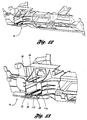
- Figures 12 and 13 show additional perspective views of the cross-car beam 16.
- the upper and lower gear racks 26,28 of the aperture 22 are clearly visible.
- the functionality of the steering column armature assembly 18 is most clearly understood with reference to the exploded view of Figure 14.
- the single handle 54 is connected to the actuator locks 64,66, which co-operate with the bulkhead stabiliser teeth 68 to form the tilt locking feature 50.
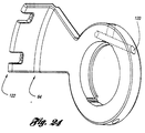
- the actuator lock 64 has an aperture 120 for receiving the single handle 54, and a locking end 122 which co-operates with the lock teeth 124 and stabiliser teeth 68 of the armature assembly 36, shown in Figure 25, to form the tilt locking feature 50.
- the hub drivers 70,72 are connected to the respective first gears (outer gears) 74,76, respectively, and to the actuator locks 64,66.
- a clutch 78,80 is secured to each first gear 74,76.
- each clutch 78,80 includes two enlarged holes 82,84 with corresponding energy dissipating slots 86,88. Pins extending from the respective first gear 74,76 engage within the holes 82,84, and are forced through the energy dissipating slots 86,88 in a crash situation for energy dissipation when the clutch 78,80 is forced to rotate with respect to the respective first gear 74,76.
- the pins 90,92 engageable within the holes 82,84 are shown in Figure 14.
- the second gears (inner gears)94,96 are attached to the driven hubs 98,100, and assembled to the armature 102.
- a hub driver 70 and driven hub 98 are shown in Figures 22 and 23. Severely canted mating threads 118,120 are provided to enable the fast lead operation.
- the hub driver 70 and driven hub 98 are moulded components.
- the actuator locks 64,66 and fast lead hub drivers 70,72 also rotate 20 degrees. With this rotation, the driven hubs 98,100 move approximately .125 inch, taking the inner gears 94,96 with them. This unlocks the actuator locks 64,66 from the bulkhead stabiliser teeth 68. At this point, only column tilt can be adjusted.
- the actuator locks 64,66 and fast lead screw hub drivers 70,72 also rotate 20 degrees more. With this rotation, the driven hubs 98,100 move approximately .125 inch more, taking the inner gears 94,96 with them.
- the tilt feature is re-locked at this point and, as shown in Figure 18, the side teeth 104 of the inner gear 94 are now spaced away from the side teeth 106 of the clutch 78, thereby allowing free counter-rotation of the inner gear 94 with respect to the attached clutch 78 and outer gear 74.
- the cross-car beam aperture 22 (receiver box) includes the gear racks 26,28. As shown, each gear rack 26,28 includes an outer row 114 and inner row 112 of teeth. The outermost teeth 114 engage the outer gear 74 at the bottom of the aperture 22, and the innermost teeth 112 engage the inner gear 94 at the top of the aperture 22. This gear arrangement stabilises the column assembly.
- the side teeth 104,106 of the inner gear 94 and clutch 78 prevent relative rotation between the clutch 78 and inner gear 94.
- the engaging side teeth 104,106 of inner gear 94 and the clutch 78 are shown in Figures 20 and 21.
- the clutch 78 is pinned to the outer gear 74 by the pins 90,92 shown in Figure 14.
- the pins 90,92 engage within the holes 80,82 of the clutch 78.
- the holes 82,84 are larger than the corresponding slots 86,88, therefore the pins 90,92 stay in position under normal conditions.
- the weak point is the energy dissipation slots 86,88 on the clutch 78.
- the outer gear 74 When sufficient axial force is exerted on the steering column, the outer gear 74 forcibly counter-rotates with respect to the inner gear 94, and the pins 90,92 deform the slots 86,88 of the clutch 78 and dissipate the energy.
- the pins 90,92 and slots 86,88 may be replaced with a pair of wires which are cold-formed by dragging the wires through bent slots during the crash event.
- Figure 27 is a schematic illustration of the packaging space required by a sample prior art steering column assembly A in comparison with the packaging space required by the present steering column assembly B. As shown, the invention provides significant packaging space savings by incorporating tilt, telescope and energy dissipation features in the removable steering column armature assembly.
Landscapes
- Engineering & Computer Science (AREA)
- Mechanical Engineering (AREA)
- General Engineering & Computer Science (AREA)
- Chemical & Material Sciences (AREA)
- Combustion & Propulsion (AREA)
- Transportation (AREA)
- Steering Controls (AREA)
- Transmission Devices (AREA)
Abstract
Description
- The present invention relates to a vehicle steering column assembly including a rotating, travelling energy absorber for energy dissipation in a high energy impact.
- Vehicle steering column assemblies often include energy dissipation features for dissipating energy when an axial force is applied to the steering column. Such energy dissipation assemblies typically include multiple components attached to the movable steering column and to the cross-car beam or instrument panel support structure. The energy dissipation component generally includes one or more deformable metal components which are deformed automatically when the steering column is forcibly collapsed.
- Such assemblies may be labour-intensive and expensive to assemble as a result of the multiple components involved and the fact that the energy dissipation components associated with the steering column and the instrument panel support structure must be attached after installation of the steering column assembly into the vehicle. This adds difficulty and expense to the steering column assembly operation.
- Accordingly, it is desirable to provide a simplified steering column assembly including an energy dissipation structure which does not require additional installation steps for assembly.
- The present invention provides a steering column armature assembly including an integral rotating, travelling energy absorber which is installed with the steering column assembly into the vehicle, and does not require additional installation steps.
- More specifically, the present invention provides a vehicle including a receiver forming an aperture therein and having first and second gear racks at opposing sides of the aperture. A steering column armature assembly is received within the receiver aperture and includes first and second gears engaged with the first and second gear racks, respectively, in a manner to facilitate counter-rotation of the first and second gears as the steering column armature assembly is moved along the first and second gear racks. The first and second gears are selectively lockable together to prevent movement of the steering column armature assembly along the first and second gear racks. The first and second gears include an energy absorber positioned therebetween for dissipating energy when the first and second gears are forcibly displaced and counter-rotate with respect to each other in a high energy impact.
- Preferably, a clutch is positioned between the first and second gears, and the energy absorber comprises a pin extending from one of the gears and co-operating with a slot formed in the clutch. The slot has a width less than the width of the pin, whereby forced counter-rotation of the first and second gears causes the pin to be dragged through the slot which forcibly widens the slot, thus dissipating impact energy. The first and second gears are axially movable toward each other for locking and away from each other for unlocking. At least one of the first and second gears includes side teeth facing corresponding side teeth on the clutch for locking.
- It is an advantage of the invention that it provides an improved vehicle steering column assembly including an energy absorber mechanism which is installed integrally with the steering column assembly and does not require additional manufacturing steps.
- The present invention will now be described further, by way of example, with reference to the accompanying drawings, in which:
- Figure 1 shows a schematic perspective view of a cross-car beam and steering column assembly in accordance with the present invention;
- Figure 2 shows an exploded perspective view of a cross-car beam and steering column assembly in accordance with the present invention;
- Figure 3 shows a perspective view of a partially disassembled steering column armature assembly in accordance with the present invention;
- Figure 4 shows an end perspective view of the assembly of Figure 3;
- Figure 5 shows a top perspective view of the assembly of Figure 3;
- Figure 6 shows a side view of the assembly of Figure 3;
- Figure 7 shows a plan view of a steering column armature assembly in accordance with the present invention;
- Figure 8 shows a perspective view of the assembly of Figure 7;
- Figure 9 shows a side view of the assembly of the Figure 7;
- Figure 10 shows an end view of the assembly of Figure 7;
- Figure 11 shows an exploded perspective view of an instrument panel assembly and cross-car beam in accordance with the present invention;
- Figure 12 shows a perspective view of a cross-car beam in accordance with the present invention;
- Figure 13 shows an enlarged partial perspective view of the cross-car beam shown in Figure 12;
- Figure 14 shows an exploded view of the assembly as shown in Figure 7;
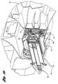
- Figure 15 shows a partial perspective view of the steering column armature assembly shown in Figure 7 received within the cross-car beam structure shown in Figure 13;
- Figure 16 shows a cut-away perspective view of the assembly of Figure 15 with the telescope assembly in the unlocked position;
- Figure 17 shows a cut-away perspective view of the assembly of Figure 15 with the telescope assembly in the locked position;
- Figure 18 shows a vertical cross-sectional view of the assembly of Figure 16;
- Figure 19 shows a vertical cross-sectional view of the assembly of Figure 17;
- Figure 20 shows a perspective view of a clutch in accordance with the present invention;
- Figure 21 shows a perspective view of a second gear engageable with the clutch of Figure 20;
- Figure 22 shows a perspective view of a hub driver in accordance with the present invention;
- Figure 23 shows a perspective view of a driven hub engageable with the hub driver of Figure 22;
- Figure 24 shows a perspective view of a tilt locking feature in accordance with the present invention;
- Figure 25 shows a perspective view of a steering column armature in accordance with the present invention;
- Figure 25a shows a reverse partial perspective view of the armature of Figure 25;
- Figure 26 shows a plan view of a clutch in accordance with the present invention; and
- Figure 27 shows a comparative schematic illustration of packaging space required by a prior art steering column assembly in comparison with the present invention.
-
- Figure 1 shows a schematic perspective view of a
vehicle 10 in accordance with the present invention. Thevehicle 10 includes A-pillars 12,14, with across-car beam 16 connecting theA-pillars column armature assembly 18 is integrated with thecross-car beam 16 for mounting asteering wheel 20 in the vehicle. - In the preferred embodiment of the invention shown in Figure 2, a partially disassembled steering
column armature assembly 18 is shown prior to installation within anaperture 22 formed in thecross-car beam 16. Preferably, thecross-car beam 16 is a cast component, wherein theaperture 22 is cast integrally therein, and thegear racks aperture 22. The gear racks 26,28 at the upper and lower edges of theaperture 22 are configured to engage thegear sets column armature assembly 18 such that the steeringcolumn armature assembly 18 may be telescopically adjusted with respect to theaperture 22 by moving thegear sets gear racks gear sets pivot joint 34 of the partially disassembled steeringcolumn armature assembly 18 to thecross-car beam 16. - Figures 3-6 show various views of the partially disassembled steering
column armature assembly 18, which includes thegear sets armature 36 which houses thesteering column 38. - Figures 7-10 show the fully assembled steering
column armature assembly 18. As shown, the steeringcolumn armature assembly 18 includes ahousing 40 havingrollers aperture 22 of thecross-car beam 16, as shown in Figure 15. The steeringcolumn armature assembly 18 shown in Figures 7-10 is a self-contained assembly, including tilting, telescoping and energy absorption features incorporated therein. Thesteering column armature 36 is pivotable about thepivot joint 34 when unrestricted by thetilt locking feature 50, to be described below. Also, the entire steering column armature assembly is movable along theaperture 22 for telescoping adjustment when unrestricted by thetelescope locking feature 52, which is incorporated within thegear sets - A
single bail handle 54 is operatively connected to thetilt locking feature 50 and to thetelescope locking feature 52 for selectively disengaging the tilt locking feature and telescope locking feature for adjustment of thesteering column 38. - Figure 11 shows an exploded view of various instrument panel and column components, including the upper
instrument panel substrate 56 and lowerinstrument panel substrate 58, which co-operate to enclose thecross-car beam 16. Also, a grommet 60 andshroud assembly 62 are provided for enclosing the steering column assembly. - Figures 12 and 13 show additional perspective views of the
cross-car beam 16. In Figure 13, the upper and lower gear racks 26,28 of theaperture 22 are clearly visible. - The functionality of the steering
column armature assembly 18 is most clearly understood with reference to the exploded view of Figure 14. Thesingle handle 54 is connected to the actuator locks 64,66, which co-operate with the bulkhead stabiliser teeth 68 to form thetilt locking feature 50. As shown in Figure 24, theactuator lock 64 has anaperture 120 for receiving thesingle handle 54, and a lockingend 122 which co-operates with thelock teeth 124 and stabiliser teeth 68 of thearmature assembly 36, shown in Figure 25, to form thetilt locking feature 50. Thehub drivers first gear 74,76. As shown in Figure 26, each clutch 78,80 includes twoenlarged holes energy dissipating slots first gear 74,76 engage within theholes energy dissipating slots first gear 74,76. Thepins holes - The second gears (inner gears)94,96 are attached to the driven hubs 98,100, and assembled to the
armature 102. Ahub driver 70 and drivenhub 98 are shown in Figures 22 and 23. Severely canted mating threads 118,120 are provided to enable the fast lead operation. Preferably, thehub driver 70 and drivenhub 98 are moulded components. - When the
single handle 54 is rotated approximately 20 degrees, the actuator locks 64,66 and fastlead hub drivers inner gears - When the
single handle 54 is rotated approximately 20 degrees more for a total of 40 degrees, the actuator locks 64,66 and fast leadscrew hub drivers inner gears side teeth 104 of theinner gear 94 are now spaced away from theside teeth 106 of the clutch 78, thereby allowing free counter-rotation of theinner gear 94 with respect to the attached clutch 78 andouter gear 74. This counter-rotation is facilitated by theinner gear 94 being engaged only with therack 28 at the bottom 108 of theaperture 22, and theouter gear 74 being engaged only at therack 28 at the top 110 of theaperture 22. The opposite edge of each of thegears inner gear 94 only engaged at the bottom, and the gear teeth of theouter gear 74 only engaged at the top, telescoping movement of the steering column assembly occurs by means of counter-rotation of thegears handle 54 movement, only column telescope can be adjusted. - Moving the
single handle 54 back 40 degrees reverses thehub drivers inner gear 94 and clutch 78, thereby locking in the newly-selected tilt and telescope positions. This locked position is shown in Figures 17 and 19, with Figures 16 and 18 illustrating the unlocked position. As shown in Figure 19, the face teeth 104,106 of theinner gear 94 and clutch 78 are engaged, thereby preventing counter-rotation of theinner gear 94 andouter gear 74, preventing telescoping movement. - Returning to Figure 13, the cross-car beam aperture 22 (receiver box) includes the gear racks 26,28. As shown, each
gear rack outer row 114 andinner row 112 of teeth. Theoutermost teeth 114 engage theouter gear 74 at the bottom of theaperture 22, and theinnermost teeth 112 engage theinner gear 94 at the top of theaperture 22. This gear arrangement stabilises the column assembly. - During the crash event, the side teeth 104,106 of the
inner gear 94 and clutch 78 prevent relative rotation between the clutch 78 andinner gear 94. The engaging side teeth 104,106 ofinner gear 94 and the clutch 78 are shown in Figures 20 and 21. However, the clutch 78 is pinned to theouter gear 74 by thepins pins holes 80,82 of the clutch 78. Theholes slots pins energy dissipation slots outer gear 74 forcibly counter-rotates with respect to theinner gear 94, and thepins slots pins slots - Figure 27 is a schematic illustration of the packaging space required by a sample prior art steering column assembly A in comparison with the packaging space required by the present steering column assembly B. As shown, the invention provides significant packaging space savings by incorporating tilt, telescope and energy dissipation features in the removable steering column armature assembly.
Claims (10)
- A vehicle comprising:a receiver (16) positioned in the vehicle and having an aperture (22) formed therein with first and second gear racks (26,28) at opposing sides of the aperture;a steering column armature assembly (18) received within the receiver aperture (22) and including first and second gears (30,32) engaged with said first and second gear racks (26,28), respectively, in a manner to facilitate counter-rotation of the first and second gears (30,32) as the steering column armature assembly (18) is moved along the first and second gear racks (26,28), and wherein said first and second gears (30,32) are selectively lockable together to prevent movement of the steering column armature assembly (18) along the first and second gear racks; and
wherein said first and second gears (30,32) include an energy absorber (86,88,90,92) positioned therebetween for dissipating energy when the first and second gears (30,32) are forcibly displaced and counter-rotate with respect to each other in a high energy impact. - A vehicle as claimed in claim 1, further comprising a clutch positioned between said first and second gears, and wherein said energy absorber comprises a pin extending from one of said gears and co-operating with a slot formed in said clutch, said slot having a width less than the width of said pin, whereby forced counter-rotation of the first and second gears causes the pin to be dragged through the slot which forcibly widens the slot, thus dissipating impact energy.
- A vehicle as claimed in claim 1, wherein said first and second gears are axially movable toward each other for locking and away from each other for unlocking.
- A vehicle as claimed in claim 3, wherein at least one of said first and second gears includes side teeth facing the other of said first and second gears for locking.
- A vehicle as claimed in claim 2, wherein said clutch is fixed to one of the first and second gears and includes clutch side teeth for locking onto the other of the first and second gears.
- A vehicle as claimed in claim 5, wherein said clutch comprises a plastic material.
- A vehicle steering column assembly comprising:a receiver forming an aperture therein and having first and second gear racks at opposing sides of the aperture;a steering column armature assembly received within the receiver aperture for sliding movement along the opening and including at least one gear engaged with said gear rack, said gear being rotatable as the steering column armature assembly slides along the aperture and lockable to prevent sliding movement along the aperture; and
wherein said steering column aperture assembly includes an energy absorber which is movable with the steering column armature assembly for dissipating energy when said at least one gear is forcibly rotated along the gear rack and rotates along the gear rack in a high energy impact. - A vehicle steering column assembly as claimed in claim 7, wherein said at least one gear rack comprises first and second gear racks positioned at opposing sides of the aperture, said at least one gear comprises first and second gears engaged with the first and second gear racks, respectively, in a manner to facilitate counter-rotation of the first and second gears as the steering column armature assembly is moved along the aperture, and said first and second gears being lockable to each other to prevent movement of the steering column armature assembly along the aperture; and
wherein said energy absorber is positioned between the first and second gears for dissipating energy when the first and second gears are forcibly rotated along the gear rack and counter-rotate with respect to each other. - A vehicle steering column assembly as claimed in claim 8, further comprising a clutch positioned between said first and second gears, and wherein said energy absorber comprises a pin extending from one of said gears and co-operating with a slot formed in said clutch, said slot having a width less than the width of said pin, whereby forced counter-rotation of the first and second gears causes the pin to be dragged through the slot which forcibly widens the slot, thus dissipating impact energy.
- A vehicle comprising:a receiver forming an aperture therein and having first and second gear racks at opposing sides of the aperture;a steering column armature assembly received within the receiver aperture and including first and second gears engaged with said first and second gear racks, respectively, in a manner to facilitate counter-rotation of the first and second gears as the steering column armature assembly is moved along the first and second gear racks, and wherein said first and second gears are selectively lockable together to prevent movement of the steering column armature assembly along the first and second gear racks;
wherein said first and second gears include an energy absorber positioned therebetween for dissipating energy when the first and second gears are rotated along the gear rack and counter-rotate with respect to each other in a high energy impact; and
wherein said first and second gears are axially movable toward each other for locking and away from each other for unlocking.
Applications Claiming Priority (2)
| Application Number | Priority Date | Filing Date | Title |
|---|---|---|---|
| US392887 | 1999-09-09 | ||
| US09/392,887 US6234040B1 (en) | 1999-09-09 | 1999-09-09 | Rotating, traveling energy absorber for steering column |
Publications (2)
| Publication Number | Publication Date |
|---|---|
| EP1083110A2 true EP1083110A2 (en) | 2001-03-14 |
| EP1083110A3 EP1083110A3 (en) | 2004-03-24 |
Family
ID=23552422
Family Applications (1)
| Application Number | Title | Priority Date | Filing Date |
|---|---|---|---|
| EP00306856A Withdrawn EP1083110A3 (en) | 1999-09-09 | 2000-08-10 | Rotating, travelling energy absorber for steering column |
Country Status (2)
| Country | Link |
|---|---|
| US (1) | US6234040B1 (en) |
| EP (1) | EP1083110A3 (en) |
Cited By (3)
| Publication number | Priority date | Publication date | Assignee | Title |
|---|---|---|---|---|
| EP1932744A3 (en) * | 2006-12-13 | 2009-05-06 | Delphi Technologies, Inc. | Position control apparatus for steering column |
| CN107042758A (en) * | 2016-02-05 | 2017-08-15 | 福特全球技术公司 | Removable steering wheel and pedal for autonomous vehicle |
| CN112918545A (en) * | 2019-12-05 | 2021-06-08 | 罗伯特·博世有限公司 | Adjustable steering column for a motor vehicle |
Families Citing this family (21)
| Publication number | Priority date | Publication date | Assignee | Title |
|---|---|---|---|---|
| US6460427B1 (en) | 2002-01-28 | 2002-10-08 | Ford Global Technologies, Inc. | Adjustment linkage for tilting and telescoping a steering column assembly |
| US20030171223A1 (en) * | 2002-01-31 | 2003-09-11 | Winemiller Mark D. | Lubricating oil compositions with improved friction properties |
| DE20317344U1 (en) * | 2003-11-11 | 2004-01-08 | Dura Automotive Systems Reiche Gmbh & Co. Kg | Telescopic steering shaft |
| US7293481B2 (en) * | 2004-03-11 | 2007-11-13 | Delphi Technologies, Inc. | Single-motor power telescope and tilt steering column |
| US7281448B2 (en) * | 2004-03-18 | 2007-10-16 | Delphi Technologies, Inc. | One-touch manual telescope and tilt steering column |
| US20060283281A1 (en) * | 2005-06-20 | 2006-12-21 | Xiaoyu Li | Synchronized screw driven power telescoping and tilt mechanism for steering column |
| US7587959B2 (en) * | 2007-02-09 | 2009-09-15 | Delphi Technologies, Inc. | Steering column assembly |
| WO2015064345A1 (en) * | 2013-10-31 | 2015-05-07 | 日本精工株式会社 | Steering device |
| US10343706B2 (en) | 2015-06-11 | 2019-07-09 | Steering Solutions Ip Holding Corporation | Retractable steering column system, vehicle having the same, and method |
| US11560169B2 (en) | 2015-06-11 | 2023-01-24 | Steering Solutions Ip Holding Corporation | Retractable steering column system and method |
| CN106256651B (en) | 2015-06-16 | 2019-06-04 | 操纵技术Ip控股公司 | Retractable steering column assembly and method |
| DE102016111473A1 (en) | 2015-06-25 | 2016-12-29 | Steering Solutions Ip Holding Corporation | STATIONARY STEERING WHEEL ASSEMBLY AND METHOD |
| CN107521547B (en) | 2016-06-21 | 2020-03-10 | 操纵技术Ip控股公司 | Self-locking telescopic actuator for steering column assembly |
| US10457313B2 (en) | 2016-06-28 | 2019-10-29 | Steering Solutions Ip Holding Corporation | ADAS wheel locking device |
| US10363958B2 (en) | 2016-07-26 | 2019-07-30 | Steering Solutions Ip Holding Corporation | Electric power steering mode determination and transitioning |
| US10189496B2 (en) | 2016-08-22 | 2019-01-29 | Steering Solutions Ip Holding Corporation | Steering assembly having a telescope drive lock assembly |
| US20180086378A1 (en) * | 2016-09-27 | 2018-03-29 | Steering Solutions Ip Holding Corporation | Position detection system for a retractable steering column |
| US10351160B2 (en) | 2016-11-30 | 2019-07-16 | Steering Solutions Ip Holding Corporation | Steering column assembly having a sensor assembly |
| US10370022B2 (en) | 2017-02-13 | 2019-08-06 | Steering Solutions Ip Holding Corporation | Steering column assembly for autonomous vehicle |
| US10385930B2 (en) | 2017-02-21 | 2019-08-20 | Steering Solutions Ip Holding Corporation | Ball coupling assembly for steering column assembly |
| US10974756B2 (en) | 2018-07-31 | 2021-04-13 | Steering Solutions Ip Holding Corporation | Clutch device latching system and method |
Family Cites Families (13)
| Publication number | Priority date | Publication date | Assignee | Title |
|---|---|---|---|---|
| US1795567A (en) | 1930-05-02 | 1931-03-10 | George P Maurice | Adjustable steering-wheel post |
| USD256018S (en) | 1978-03-13 | 1980-07-22 | Massey-Ferguson Inc., | Tractor console |
| GB2113164B (en) * | 1982-01-15 | 1985-07-17 | Ford Motor Co | Mounting for an adjustable steering column |
| USD342712S (en) | 1991-10-21 | 1993-12-28 | Isuzu Motors Limited | Automobile instrument panel and steering wheel column |
| USD363053S (en) | 1993-10-13 | 1995-10-10 | Isuzu Motors Limited | Combined vehicle instrument panel and steering wheel column |
| US5606892A (en) | 1995-03-31 | 1997-03-04 | Ford Motor Company | Modular steering column assembly |
| EP0769444B1 (en) * | 1995-10-20 | 1998-09-16 | Fuji Kiko Co., Ltd. | Steering column for automotive vehicle |
| US5645299A (en) * | 1996-05-31 | 1997-07-08 | Trw Inc. | Steering column support |
| US5820163A (en) * | 1996-07-08 | 1998-10-13 | Ford Global Technologies, Inc. | Tilting, telescoping and energy absorbing steering column |
| US5737971A (en) | 1996-08-05 | 1998-04-14 | General Motors Corporation | Motor vehicle steering column |
| US5813288A (en) | 1996-08-08 | 1998-09-29 | Chrysler Corporation | Steering column close-out boot |
| US5979265A (en) * | 1997-09-11 | 1999-11-09 | Mando Machinery Corporation | Tilting and telescopic structure for steering columns |
| US6099038A (en) * | 1999-01-19 | 2000-08-08 | Daimlerchrysler Corporation | Upper and lower mounting bracket assembly for a steering column of an automotive vehicle |
-
1999
- 1999-09-09 US US09/392,887 patent/US6234040B1/en not_active Expired - Fee Related
-
2000
- 2000-08-10 EP EP00306856A patent/EP1083110A3/en not_active Withdrawn
Non-Patent Citations (1)
| Title |
|---|
| None |
Cited By (4)
| Publication number | Priority date | Publication date | Assignee | Title |
|---|---|---|---|---|
| EP1932744A3 (en) * | 2006-12-13 | 2009-05-06 | Delphi Technologies, Inc. | Position control apparatus for steering column |
| CN107042758A (en) * | 2016-02-05 | 2017-08-15 | 福特全球技术公司 | Removable steering wheel and pedal for autonomous vehicle |
| CN107042758B (en) * | 2016-02-05 | 2021-11-05 | 福特全球技术公司 | Removable steering wheel and pedals for autonomous vehicles |
| CN112918545A (en) * | 2019-12-05 | 2021-06-08 | 罗伯特·博世有限公司 | Adjustable steering column for a motor vehicle |
Also Published As
| Publication number | Publication date |
|---|---|
| US6234040B1 (en) | 2001-05-22 |
| EP1083110A3 (en) | 2004-03-24 |
Similar Documents
| Publication | Publication Date | Title |
|---|---|---|
| US6234040B1 (en) | Rotating, traveling energy absorber for steering column | |
| US6237439B1 (en) | Single release lever for steering column tilt and telescope | |
| US6152489A (en) | Integrated steering column and instrument panel structure apparatus | |
| DE69514091T2 (en) | TURNING CONNECTION FOR A LATERAL REAR VIEW MIRROR | |
| US8783717B2 (en) | Steering column telescope lock | |
| DE102019122105B3 (en) | Combined actuator for folding and lifting mirrors, rearview device and vehicle | |
| EP2055612B1 (en) | Steering column assembly | |
| US8641095B2 (en) | Steering column device | |
| EP2100795B1 (en) | Locking mechanism for an adjustable steering column having impact teeth | |
| EP1854699B1 (en) | Tliting and telescopic steering apparatus having rotatable locking member | |
| EP1468895A1 (en) | Steering device | |
| US20030226943A1 (en) | Device for clamping a member adjustable relative to a support assembly | |
| KR20040044553A (en) | Fastening construction, in particular for a wing mirror of a motor vehicle | |
| US7367589B2 (en) | Collapsible steering assembly with a stationary reaction surface | |
| DE60125270T2 (en) | Automotive rearview mirror | |
| JP4791985B2 (en) | Steering column device | |
| DE3941047C2 (en) | ||
| JP4938386B2 (en) | Movable steering device | |
| CN110271605A (en) | Steering system | |
| EP3524474B1 (en) | Connector arrangement for a motor vehicle rear-view mirror | |
| KR102267717B1 (en) | Tilt structure for steering column | |
| JPH0425897B2 (en) | ||
| EP1553003B1 (en) | Telescoping steering column assembly with brake | |
| JP2008149969A (en) | Steering column device | |
| JP2010274744A (en) | Retractable outer mirror |
Legal Events
| Date | Code | Title | Description |
|---|---|---|---|
| PUAI | Public reference made under article 153(3) epc to a published international application that has entered the european phase |
Free format text: ORIGINAL CODE: 0009012 |
|
| AK | Designated contracting states |
Kind code of ref document: A2 Designated state(s): AT BE CH CY DE DK ES FI FR GB GR IE IT LI LU MC NL PT SE |
|
| AX | Request for extension of the european patent |
Free format text: AL;LT;LV;MK;RO;SI |
|
| PUAL | Search report despatched |
Free format text: ORIGINAL CODE: 0009013 |
|
| AK | Designated contracting states |
Kind code of ref document: A3 Designated state(s): AT BE CH CY DE DK ES FI FR GB GR IE IT LI LU MC NL PT SE |
|
| AX | Request for extension of the european patent |
Extension state: AL LT LV MK RO SI |
|
| RIC1 | Information provided on ipc code assigned before grant |
Ipc: 7B 62D 1/18 B Ipc: 7B 62D 1/19 A |
|
| AKX | Designation fees paid |
Designated state(s): DE FR GB |
|
| STAA | Information on the status of an ep patent application or granted ep patent |
Free format text: STATUS: THE APPLICATION IS DEEMED TO BE WITHDRAWN |
|
| 18D | Application deemed to be withdrawn |
Effective date: 20040925 |