EP1083108A2 - Integrated steering column and instrument panel structure apparatus - Google Patents
Integrated steering column and instrument panel structure apparatus Download PDFInfo
- Publication number
- EP1083108A2 EP1083108A2 EP00306821A EP00306821A EP1083108A2 EP 1083108 A2 EP1083108 A2 EP 1083108A2 EP 00306821 A EP00306821 A EP 00306821A EP 00306821 A EP00306821 A EP 00306821A EP 1083108 A2 EP1083108 A2 EP 1083108A2
- Authority
- EP
- European Patent Office
- Prior art keywords
- cross
- car beam
- steering column
- vehicle
- gear
- Prior art date
- Legal status (The legal status is an assumption and is not a legal conclusion. Google has not performed a legal analysis and makes no representation as to the accuracy of the status listed.)
- Withdrawn
Links
- 239000006096 absorbing agent Substances 0.000 description 5
- 238000004806 packaging method and process Methods 0.000 description 4
- 230000021715 photosynthesis, light harvesting Effects 0.000 description 3
- 239000003381 stabilizer Substances 0.000 description 3
- 238000009434 installation Methods 0.000 description 2
- 238000000034 method Methods 0.000 description 2
- 239000000758 substrate Substances 0.000 description 2
- 238000010521 absorption reaction Methods 0.000 description 1
- 230000000712 assembly Effects 0.000 description 1
- 238000000429 assembly Methods 0.000 description 1
- 230000000052 comparative effect Effects 0.000 description 1
- 230000013011 mating Effects 0.000 description 1
- 238000005096 rolling process Methods 0.000 description 1
Images






Classifications
-
- B—PERFORMING OPERATIONS; TRANSPORTING
- B62—LAND VEHICLES FOR TRAVELLING OTHERWISE THAN ON RAILS
- B62D—MOTOR VEHICLES; TRAILERS
- B62D25/00—Superstructure or monocoque structure sub-units; Parts or details thereof not otherwise provided for
- B62D25/08—Front or rear portions
- B62D25/14—Dashboards as superstructure sub-units
- B62D25/145—Dashboards as superstructure sub-units having a crossbeam incorporated therein
-
- B—PERFORMING OPERATIONS; TRANSPORTING
- B62—LAND VEHICLES FOR TRAVELLING OTHERWISE THAN ON RAILS
- B62D—MOTOR VEHICLES; TRAILERS
- B62D1/00—Steering controls, i.e. means for initiating a change of direction of the vehicle
- B62D1/02—Steering controls, i.e. means for initiating a change of direction of the vehicle vehicle-mounted
- B62D1/16—Steering columns
- B62D1/18—Steering columns yieldable or adjustable, e.g. tiltable
- B62D1/184—Mechanisms for locking columns at selected positions
-
- B—PERFORMING OPERATIONS; TRANSPORTING
- B62—LAND VEHICLES FOR TRAVELLING OTHERWISE THAN ON RAILS
- B62D—MOTOR VEHICLES; TRAILERS
- B62D1/00—Steering controls, i.e. means for initiating a change of direction of the vehicle
- B62D1/02—Steering controls, i.e. means for initiating a change of direction of the vehicle vehicle-mounted
- B62D1/16—Steering columns
- B62D1/18—Steering columns yieldable or adjustable, e.g. tiltable
- B62D1/185—Steering columns yieldable or adjustable, e.g. tiltable adjustable by axial displacement, e.g. telescopically
Definitions
- the present invention relates to a vehicle having a steering column assembly integrated with a cross-car beam of the vehicle.
- vehicle steering column assemblies are complex structures requiring multiple assembly steps for installation in a vehicle.
- the steering column assembly is bracketed to the cross-car beam, which extends between A-pillars of the vehicles for providing structural integrity.
- the steering column assembly is assembled independently within its own housing, and then bracketed to the cross-car beam by means of one or more bracketing components.
- a vehicle having first and second A-pillars, the vehicle comprising: a cross-car beam connecting the first and second A-pillars of the vehicle; a steering column armature assembly positioned within the vehicle and including at least one pivot joint; and a single attachment component directly connecting said pivot joint to the cross-car beam.
- a vehicle comprising: a cross-car beam connected at opposing ends to the first and second A-pillars of the vehicle, said cross-car beam having an aperture formed therethrough; and a steering column armature assembly slidably received within said aperture and supported by the cross-car beam.
- the cross-car beam itself may form the housing for the steering column, or a single attachment component may directly connect a pivot joint of the steering column assembly to the cross-car beam.
- the single attachment component may be operative as a steering column housing while attaching the pivot joint to the cross-car beam, which eliminates the need for extra attachment brackets.
- the cross-car beam may include an aperture formed therethrough for receiving the steering column armature assembly.
- the single attachment component would include a gear pivotally connected coaxially with the pivot joint and having gear teeth engaged with a gear rack formed integrally with the cross-car beam for pivotally mounting the pivot joint with respect to the cross-car beam.
- the steering column armature assembly is integrally attached with the cross-car beam by a single attachment component, thereby reducing part count and simplifying the assembly process.
- FIG. 1 shows a schematic perspective view of a vehicle 10 in accordance with the present invention.
- the vehicle 10 includes A-pillars 12,14, with a cross-car beam 16 connecting the A-pillars 12,14.
- a steering column armature assembly 18 is integrated with the cross-car beam 16 for mounting a steering wheel 20 in the vehicle.
- a partially disassembled steering column armature assembly 18 is shown prior to installation within an aperture 22 formed in the cross-car beam 16.
- the cross-car beam 16 is a cast component, wherein the aperture 22 is cast integrally therein, and the gear racks 26,28 are formed on upper and lower sides of the aperture 22.
- the gear racks 26,28 at the upper and lower edges of the aperture 22 are configured to engage the gear sets 30,32 of the steering column armature assembly 18 such that the steering column armature assembly 18 may be telescopically adjusted with respect to the aperture 22 by moving the gear sets 30,32 along the gear racks 26,28.
- a single gear of the gear sets 30,32 may act as a single attachment component for directly connecting a pivot joint 34 of the partially disassembled steering column armature assembly 18 to the cross-car beam 16.
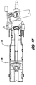
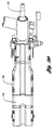
- Figures 3-6 show various views of the partially disassembled steering column armature assembly 18, which includes the gear sets 30,32 and armature 36 which houses the steering column 38.
- Figures 7-10 show the fully assembled steering column armature assembly 18.
- the steering column armature assembly 18 includes a housing 40 having rollers 42,44,46 for rolling movement within the aperture 22 of the cross-car beam 16, as shown in Figure 15.
- the steering column armature assembly 18 shown in Figures 7-10 is a self-contained assembly, including tilting, telescoping and energy absorption features incorporated therein.
- the steering column armature 36 is pivotable about the pivot joint 34 when unrestricted by the tilt locking feature 50, to be described below.
- the entire steering column armature assembly is movable along the aperture 22 for telescoping adjustment when unrestricted by the telescope locking feature 52, which is incorporated within the gear sets 30,32, to be described below.
- a single bail handle 54 is operatively connected to the tilt locking feature 50 and to the telescope locking feature 52 for selectively disengaging the tilt locking feature and telescope locking feature for adjustment of the steering column 38.
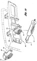
- Figure 11 shows an exploded view of various instrument panel and column components, including the upper instrument panel substrate 56 and lower instrument panel substrate 58, which co-operate to enclose the cross-car beam 16. Also, a grommet 60 and shroud assembly 62 are provided for enclosing the steering column assembly.
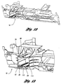
- Figures 12 and 13 show additional perspective views of the cross-car beam 16.
- the upper and lower gear racks 26,28 of the aperture 22 are clearly visible.
- the functionality of the steering column armature assembly 18 is most clearly understood with reference to the exploded view of Figure 14.
- the single handle 54 is connected to the actuator locks 64,66, which co-operate with the bulkhead stabiliser teeth 68.
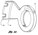
- the actuator lock 64 has an aperture 120 for receiving the single handle 54, and a locking end 122 which co-operates with the lock teeth 124 and stabiliser teeth 68 of the armature assembly 36, shown in Figure 25, to form the tilt locking feature 50.
- the hub drivers 70,72 are connected to the respective first gears (outer gears) 74,76, respectively, and to the actuator locks 64,66.
- a clutch 78,80 is secured to each first gear 74,76.
- each clutch 78,80 includes two enlarged holes 82,84 with corresponding energy dissipating slots 86,88. Pins extending from the respective first gear 74,76 engage within the holes 82,84, and are forced through the energy dissipating slots 86,88 in a crash situation for energy dissipation when the clutch 78,80 is forced to rotate with respect to the respective first gear 74,76.
- the pins 90,92 engageable within the holes 82,84 are shown in Figure 14.
- the second gears (inner gears) 94,96 are attached to the driven hubs 98,100, and assembled to the armature 102.
- a hub driver 70 and driven hub 98 are shown in Figures 22 and 23. Severely canted mating threads 118,120 are provided to enable the fast lead operation.
- the hub driver 70 and driven hub 98 are moulded components.
- the actuator locks 64,66 and fast lead hub drivers 70,72 also rotate 20 degrees. With this rotation, the driven hubs 98,100 move approximately .125 inch, taking the inner gears 94,96 with them. This unlocks the actuator locks 64,66 from the bulkhead stabiliser teeth 68. At this point, only column tilt can be adjusted.
- the actuator locks 64,66 and fast lead screw hub drivers 70,72 also rotate 20 degrees more. With this rotation, the driven hubs 98,100 move approximately .125 inch more, taking the inner gears 94,96 with them.
- the side teeth 104 of the inner gear 94 are now spaced away from the side teeth 106 of the clutch 78, thereby allowing free counter-rotation of the inner gear 94 with respect to the attached clutch 78 and outer gear 74. This counter-rotation is facilitated by the inner gear 94 being engaged only with the rack 28 at the bottom 108 of the aperture 22, and the outer gear 74 being engaged only at the rack 28 at the top 110 of the aperture 22.
- each of the gears 74,94 is provided with clearance from the opposing aperture wall. Accordingly, with the gear teeth of the inner gear 94 only engaged at the bottom, and the gear teeth of the outer gear 74 only engaged at the top, telescoping movement of the steering column assembly occurs by means of counter-rotation of the gears 74,94. At this point of 40 degrees of handle 54 movement, only column telescope can be adjusted.
- the cross-car beam aperture 22 (receiver box) includes the gear racks 26,28. As shown, each gear rack 26,28 includes an outer row 114 and inner row 112 of teeth. The outermost teeth 114 engage the outer gear 74 at the bottom of the aperture 22, and the innermost teeth 112 engage the inner gear 94 at the top of the aperture 22. This gear arrangement stabilises the column assembly.
- the side teeth 104,106 of the clutch 78 and inner gear 94 prevent relative rotation between the clutch 78 and inner gear 94.
- the engaging side teeth 104,106 of the clutch 78 and inner gear 94 are shown in Figures 20 and 21.
- the clutch 78 is pinned to the outer gear 74 by the pins 90,92 shown in Figure 14.
- the pins 90,92 engage within the holes 80,82 of the clutch 78.
- the holes 82,84 are larger than the corresponding slots 86,88, therefore the pins 90,92 stay in position under normal conditions.
- the weak point is the energy dissipation slots 86,88 on the clutch 78.
- the outer gear 74 When sufficient axial force is exerted on the steering column, the outer gear 74 forcibly counter-rotates with respect to the inner gear 94, and the pins 90,92 deform the slots 86,88 of the clutch 78 and dissipate the energy.
- the pins 90,92 and slots 86,88 may be replaced with a pair of wires which are cold-formed by dragging the wires through bent slots during the crash event.
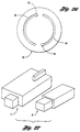
- Figure 27 is a schematic illustration of the packaging space required by a sample prior art steering column assembly A in comparison with the packaging space required by the present steering column assembly B. As shown, the invention provides significant packaging space savings by incorporating tilt, telescope and energy dissipation features in the removable steering column armature assembly.
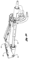
- the steering column 130 includes a pivot joint 132 which is directly attached to a cross-car beam at an attachment location 134 of a single attachment component 136. Accordingly, the single attachment component 136 not only attaches the pivot joint 132 of the steering column 130 directly to the cross-car beam, but also acts as a housing for the steering column 30. In this manner, part count is reduced because no additional bracketing is required for attachment.
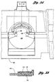
- Figures 31-35 illustrate a second alternative embodiment of the invention wherein a cross-car beam 150 includes an aperture 152 for receiving a steering column armature assembly 154 and an absorber bracket 156. As shown, the cross-car beam 150 includes support ribs 158,160 positioned within aperture 152 for co-operation with the slots 162,164, respectively, of the absorber bracket 156.
- each slot 164 includes steps 176,178 so that the support ribs 160 are sequentially tightened as each rib 160 is inserted into the respective slot 164.
- a bolt 166 attaches the steering column armature assembly 154 to the absorber bracket 156.
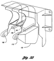
- FIG. 33 A rear perspective view of the cross-car beam 150 is shown in Figure 33.
- the cross-car beam 150 includes apertures 168,170 to which the pivot joint 172 of the steering column armature assembly 154 is attached.
- An energy absorbing curl strap (not shown) is connected between the absorber bracket 156 and the cross-car beam 150 for dissipating energy as the internally collapsing steering column armature assembly 154 is collapsed in a high energy impact.
Landscapes
- Engineering & Computer Science (AREA)
- Chemical & Material Sciences (AREA)
- Combustion & Propulsion (AREA)
- Transportation (AREA)
- Mechanical Engineering (AREA)
- Steering Controls (AREA)
- Body Structure For Vehicles (AREA)
- Instrument Panels (AREA)
Abstract
Description
Claims (6)
- A vehicle having first and second A-pillars, the vehicle comprising:a cross-car beam (16) connecting the first and second A-pillars (12,14) of the vehicle;a steering column armature assembly (18) positioned within the vehicle and including at least one pivot joint (34); anda single attachment component (30,32) directly connecting said pivot joint (34) to the cross-car beam (16).
- A vehicle as claimed in claim 1, wherein said single attachment component is further operative as a steering column housing.
- A vehicle as claimed in claim 1, wherein said cross-car beam comprises an aperture formed therethrough for receiving the steering column armature assembly, and said single attachment component comprises a gear pivotally connected coaxially with said pivot joint and having gear teeth engaged with a gear rack formed integrally with the cross-car beam for pivotally mounting the pivot joint with respect to the cross-car beam.
- A vehicle comprising:a cross-car beam connected at opposing ends to the first and second A-pillars of the vehicle, said cross-car beam having an aperture formed therethrough; anda steering column armature assembly slidably received within said aperture and supported by the cross-car beam.
- A vehicle as claimed in claim 4, wherein said cross-car beam comprises a one-piece cast component with a gear rack formed integrally therewith, and said steering column armature assembly includes a gear engaged with the gear rack.
- A vehicle having first and second A-pillars, the vehicle comprising:a cast, one-piece cross-car beam connected at opposing ends to the A-pillars, and said cross-car beam having an aperture formed therethrough and having a gear rack formed integrally with the cross-car beam; anda steering column armature assembly slidably received within said aperture and supported by the cross-car beam, said steering column armature assembly including a gear engaged with said gear rack.
Applications Claiming Priority (2)
| Application Number | Priority Date | Filing Date | Title |
|---|---|---|---|
| US392889 | 1999-09-09 | ||
| US09/392,889 US6152489A (en) | 1999-09-09 | 1999-09-09 | Integrated steering column and instrument panel structure apparatus |
Publications (2)
| Publication Number | Publication Date |
|---|---|
| EP1083108A2 true EP1083108A2 (en) | 2001-03-14 |
| EP1083108A3 EP1083108A3 (en) | 2004-04-14 |
Family
ID=23552432
Family Applications (1)
| Application Number | Title | Priority Date | Filing Date |
|---|---|---|---|
| EP00306821A Withdrawn EP1083108A3 (en) | 1999-09-09 | 2000-08-10 | Integrated steering column and instrument panel structure apparatus |
Country Status (3)
| Country | Link |
|---|---|
| US (1) | US6152489A (en) |
| EP (1) | EP1083108A3 (en) |
| JP (1) | JP2001122133A (en) |
Cited By (2)
| Publication number | Priority date | Publication date | Assignee | Title |
|---|---|---|---|---|
| FR3059969A1 (en) * | 2016-12-14 | 2018-06-15 | Peugeot Citroen Automobiles Sa | MANUALLY RETRACTABLE STEERING COLUMN FOR A VEHICLE |
| DE102019114991A1 (en) * | 2019-06-04 | 2020-12-10 | Bayerische Motoren Werke Aktiengesellschaft | Steering column cover and steering column with a steering column cover |
Families Citing this family (17)
| Publication number | Priority date | Publication date | Assignee | Title |
|---|---|---|---|---|
| US6237956B1 (en) * | 2000-04-17 | 2001-05-29 | Lear Corporation | Steering column support bracket |
| JP4628561B2 (en) * | 2001-02-23 | 2011-02-09 | 富士重工業株式会社 | Steering column mounting structure |
| US6708583B2 (en) | 2001-04-18 | 2004-03-23 | Bayer Polymers Llc | Shaft support structure |
| US6398259B1 (en) | 2001-04-18 | 2002-06-04 | Bayer Corporation | Break-away bracket |
| FR2828856B1 (en) * | 2001-08-22 | 2003-12-05 | Sai Automotive Allibert Ind | DEVICE FOR MASKING GAMES BETWEEN AN INSTRUMENT PANEL AND A COVER ELEMENT LINKED TO AN ADJUSTABLE STEERING COLUMN |
| US6460427B1 (en) | 2002-01-28 | 2002-10-08 | Ford Global Technologies, Inc. | Adjustment linkage for tilting and telescoping a steering column assembly |
| US6756004B2 (en) | 2002-04-24 | 2004-06-29 | Lear Corporation | Method for manufacturing cockpit-type instrument panels |
| US7000949B2 (en) * | 2002-12-13 | 2006-02-21 | Takata-Petri, Inc. | Steering column module |
| DE20317344U1 (en) * | 2003-11-11 | 2004-01-08 | Dura Automotive Systems Reiche Gmbh & Co. Kg | Telescopic steering shaft |
| US20060107784A1 (en) * | 2003-12-16 | 2006-05-25 | Takata-Petri, Inc. | Steering column module |
| US20060001191A1 (en) * | 2004-06-21 | 2006-01-05 | Ipl Inc. | Shroud assembly and a method of fabrication thereof |
| JP4459084B2 (en) * | 2005-02-28 | 2010-04-28 | 本田技研工業株式会社 | Vehicle with power steering device |
| US7264295B2 (en) * | 2005-07-26 | 2007-09-04 | Visteon Global Technologies, Inc. | Vehicle cockpit attachment structure with integrated plastic composite functional molded features |
| WO2008120232A2 (en) * | 2007-03-30 | 2008-10-09 | Tata Motors Limited | Improved steering column support structure |
| DE102009026299A1 (en) * | 2009-07-31 | 2011-02-03 | Thyssenkrupp Steel Europe Ag | Cockpit transverse beam for motor vehicle, has metal section arranged at vehicle side and two flat portions, where flat portions are partially integrated as cross-section wall elements in metal section |
| US8534739B2 (en) | 2011-05-27 | 2013-09-17 | Ford Global Technologies, Llc | Cross car beam assembly including reinforced polymerized elements |
| JP6079752B2 (en) * | 2014-11-17 | 2017-02-15 | トヨタ自動車株式会社 | Steering support structure |
Family Cites Families (15)
| Publication number | Priority date | Publication date | Assignee | Title |
|---|---|---|---|---|
| US1795567A (en) * | 1930-05-02 | 1931-03-10 | George P Maurice | Adjustable steering-wheel post |
| CH301312A (en) * | 1951-02-24 | 1954-08-31 | Daimler Benz Ag | Combination instrument. |
| DE2230775C3 (en) * | 1972-06-23 | 1982-01-14 | Audi Nsu Auto Union Ag, 7107 Neckarsulm | Dashboard for automobiles |
| USD256018S (en) | 1978-03-13 | 1980-07-22 | Massey-Ferguson Inc., | Tractor console |
| DE3016212A1 (en) * | 1980-04-26 | 1981-10-29 | Volkswagenwerk Ag, 3180 Wolfsburg | LENGTH AND TILT ADJUSTABLE STEERING COLUMN FOR A VEHICLE |
| JPS57177873U (en) * | 1981-05-07 | 1982-11-10 | ||
| GB2113164B (en) * | 1982-01-15 | 1985-07-17 | Ford Motor Co | Mounting for an adjustable steering column |
| USD342712S (en) | 1991-10-21 | 1993-12-28 | Isuzu Motors Limited | Automobile instrument panel and steering wheel column |
| US5282637A (en) * | 1991-12-13 | 1994-02-01 | Ford Motor Company | Mount for vehicle front support structure |
| US5238296A (en) * | 1991-12-30 | 1993-08-24 | Paul Gerald S | Foot rocker |
| USD363053S (en) | 1993-10-13 | 1995-10-10 | Isuzu Motors Limited | Combined vehicle instrument panel and steering wheel column |
| US5606892A (en) * | 1995-03-31 | 1997-03-04 | Ford Motor Company | Modular steering column assembly |
| US5737971A (en) * | 1996-08-05 | 1998-04-14 | General Motors Corporation | Motor vehicle steering column |
| US5813288A (en) * | 1996-08-08 | 1998-09-29 | Chrysler Corporation | Steering column close-out boot |
| US5934733A (en) * | 1997-12-19 | 1999-08-10 | General Motors Corporation | Extruded instrument panel structure |
-
1999
- 1999-09-09 US US09/392,889 patent/US6152489A/en not_active Expired - Fee Related
-
2000
- 2000-08-10 EP EP00306821A patent/EP1083108A3/en not_active Withdrawn
- 2000-09-08 JP JP2000273479A patent/JP2001122133A/en active Pending
Cited By (4)
| Publication number | Priority date | Publication date | Assignee | Title |
|---|---|---|---|---|
| FR3059969A1 (en) * | 2016-12-14 | 2018-06-15 | Peugeot Citroen Automobiles Sa | MANUALLY RETRACTABLE STEERING COLUMN FOR A VEHICLE |
| WO2018109296A1 (en) * | 2016-12-14 | 2018-06-21 | Psa Automobiles Sa | Manually retractable steering column for a vehicle |
| DE102019114991A1 (en) * | 2019-06-04 | 2020-12-10 | Bayerische Motoren Werke Aktiengesellschaft | Steering column cover and steering column with a steering column cover |
| US11845486B2 (en) | 2019-06-04 | 2023-12-19 | Bayerische Motoren Werke Aktiengesellschaft | Steering column cover and steering column having a steering column cover |
Also Published As
| Publication number | Publication date |
|---|---|
| EP1083108A3 (en) | 2004-04-14 |
| JP2001122133A (en) | 2001-05-08 |
| US6152489A (en) | 2000-11-28 |
Similar Documents
| Publication | Publication Date | Title |
|---|---|---|
| US6152489A (en) | Integrated steering column and instrument panel structure apparatus | |
| US6234040B1 (en) | Rotating, traveling energy absorber for steering column | |
| US6237439B1 (en) | Single release lever for steering column tilt and telescope | |
| US8783717B2 (en) | Steering column telescope lock | |
| US3373629A (en) | Steering column assembly | |
| KR100238856B1 (en) | Car seat structure | |
| US10099715B2 (en) | Stationary energy absorption strap control assembly for vehicle steering column | |
| US7367589B2 (en) | Collapsible steering assembly with a stationary reaction surface | |
| US20030226943A1 (en) | Device for clamping a member adjustable relative to a support assembly | |
| US20110210537A1 (en) | Steering column device | |
| US6272945B1 (en) | Tilt release system for a steering column | |
| JP3335485B2 (en) | Vehicle steering column | |
| KR100510417B1 (en) | Tilt steering column mounted to a vehicle by brackets providing high stiffness | |
| JP2008055982A (en) | Movable steering device | |
| JP3788039B2 (en) | Shock absorbing steering column device | |
| US20050104355A1 (en) | Impact absorbing steering column device | |
| JP4938386B2 (en) | Movable steering device | |
| EP3072780B1 (en) | Steering column device for absorbing impact energy | |
| CN110271605A (en) | Steering system | |
| US7134692B2 (en) | Impact absorbing structure for vehicle steering systems | |
| US7393014B2 (en) | Energy absorbing support for a vehicle steering assembly | |
| JP2513633Y2 (en) | Shock absorption type steering column device | |
| US20120006142A1 (en) | Tilt hinge bracket of steering column for vehicle and steering column for vehicle having the same | |
| US20050046163A1 (en) | Impact absorption structure of a steering column cover for a vehicle | |
| JP4628092B2 (en) | Steering column device |
Legal Events
| Date | Code | Title | Description |
|---|---|---|---|
| PUAI | Public reference made under article 153(3) epc to a published international application that has entered the european phase |
Free format text: ORIGINAL CODE: 0009012 |
|
| AK | Designated contracting states |
Kind code of ref document: A2 Designated state(s): AT BE CH CY DE DK ES FI FR GB GR IE IT LI LU MC NL PT SE |
|
| AX | Request for extension of the european patent |
Free format text: AL;LT;LV;MK;RO;SI |
|
| PUAL | Search report despatched |
Free format text: ORIGINAL CODE: 0009013 |
|
| AK | Designated contracting states |
Kind code of ref document: A3 Designated state(s): AT BE CH CY DE DK ES FI FR GB GR IE IT LI LU MC NL PT SE |
|
| AX | Request for extension of the european patent |
Extension state: AL LT LV MK RO SI |
|
| AKX | Designation fees paid |
Designated state(s): DE FR GB |
|
| STAA | Information on the status of an ep patent application or granted ep patent |
Free format text: STATUS: THE APPLICATION IS DEEMED TO BE WITHDRAWN |
|
| 18D | Application deemed to be withdrawn |
Effective date: 20041015 |