EP1082772B1 - Method for the integration of fuel cells into electrochemical plants - Google Patents
Method for the integration of fuel cells into electrochemical plants Download PDFInfo
- Publication number
- EP1082772B1 EP1082772B1 EP99920771A EP99920771A EP1082772B1 EP 1082772 B1 EP1082772 B1 EP 1082772B1 EP 99920771 A EP99920771 A EP 99920771A EP 99920771 A EP99920771 A EP 99920771A EP 1082772 B1 EP1082772 B1 EP 1082772B1
- Authority
- EP
- European Patent Office
- Prior art keywords
- fuel cells
- electrolyzers
- voltage
- modules
- hydrogen
- Prior art date
- Legal status (The legal status is an assumption and is not a legal conclusion. Google has not performed a legal analysis and makes no representation as to the accuracy of the status listed.)
- Expired - Lifetime
Links
- 239000000446 fuel Substances 0.000 title claims abstract description 59
- 238000000034 method Methods 0.000 title claims abstract description 14
- 230000010354 integration Effects 0.000 title description 5
- 239000001257 hydrogen Substances 0.000 claims abstract description 17
- 229910052739 hydrogen Inorganic materials 0.000 claims abstract description 17
- UFHFLCQGNIYNRP-UHFFFAOYSA-N Hydrogen Chemical compound [H][H] UFHFLCQGNIYNRP-UHFFFAOYSA-N 0.000 claims abstract description 15
- 239000006227 byproduct Substances 0.000 claims abstract description 4
- 230000001105 regulatory effect Effects 0.000 claims abstract 3
- 238000006243 chemical reaction Methods 0.000 claims description 3
- 230000008878 coupling Effects 0.000 abstract 1
- 238000010168 coupling process Methods 0.000 abstract 1
- 238000005859 coupling reaction Methods 0.000 abstract 1
- 238000005265 energy consumption Methods 0.000 abstract 1
- 239000002585 base Substances 0.000 description 5
- 238000005868 electrolysis reaction Methods 0.000 description 5
- XTEGARKTQYYJKE-UHFFFAOYSA-M Chlorate Chemical compound [O-]Cl(=O)=O XTEGARKTQYYJKE-UHFFFAOYSA-M 0.000 description 4
- VEXZGXHMUGYJMC-UHFFFAOYSA-N Hydrochloric acid Chemical compound Cl VEXZGXHMUGYJMC-UHFFFAOYSA-N 0.000 description 4
- 239000012528 membrane Substances 0.000 description 4
- 239000007789 gas Substances 0.000 description 3
- 239000000126 substance Substances 0.000 description 3
- 239000003513 alkali Substances 0.000 description 2
- 238000009434 installation Methods 0.000 description 2
- 238000004519 manufacturing process Methods 0.000 description 2
- ZAMOUSCENKQFHK-UHFFFAOYSA-N Chlorine atom Chemical compound [Cl] ZAMOUSCENKQFHK-UHFFFAOYSA-N 0.000 description 1
- 230000004913 activation Effects 0.000 description 1
- QVGXLLKOCUKJST-UHFFFAOYSA-N atomic oxygen Chemical compound [O] QVGXLLKOCUKJST-UHFFFAOYSA-N 0.000 description 1
- 230000003197 catalytic effect Effects 0.000 description 1
- 239000000460 chlorine Substances 0.000 description 1
- 229910052801 chlorine Inorganic materials 0.000 description 1
- 239000013065 commercial product Substances 0.000 description 1
- 230000000295 complement effect Effects 0.000 description 1
- 230000003247 decreasing effect Effects 0.000 description 1
- 238000010586 diagram Methods 0.000 description 1
- 238000010438 heat treatment Methods 0.000 description 1
- 150000002431 hydrogen Chemical class 0.000 description 1
- 238000005342 ion exchange Methods 0.000 description 1
- 239000001301 oxygen Substances 0.000 description 1
- 229910052760 oxygen Inorganic materials 0.000 description 1
- 238000011084 recovery Methods 0.000 description 1
- 230000003068 static effect Effects 0.000 description 1
Images



Classifications
-
- H—ELECTRICITY
- H01—ELECTRIC ELEMENTS
- H01M—PROCESSES OR MEANS, e.g. BATTERIES, FOR THE DIRECT CONVERSION OF CHEMICAL ENERGY INTO ELECTRICAL ENERGY
- H01M8/00—Fuel cells; Manufacture thereof
- H01M8/24—Grouping of fuel cells, e.g. stacking of fuel cells
-
- H—ELECTRICITY
- H01—ELECTRIC ELEMENTS
- H01M—PROCESSES OR MEANS, e.g. BATTERIES, FOR THE DIRECT CONVERSION OF CHEMICAL ENERGY INTO ELECTRICAL ENERGY
- H01M8/00—Fuel cells; Manufacture thereof
- H01M8/04—Auxiliary arrangements, e.g. for control of pressure or for circulation of fluids
- H01M8/04298—Processes for controlling fuel cells or fuel cell systems
- H01M8/04694—Processes for controlling fuel cells or fuel cell systems characterised by variables to be controlled
- H01M8/04746—Pressure; Flow
- H01M8/04753—Pressure; Flow of fuel cell reactants
-
- C—CHEMISTRY; METALLURGY
- C25—ELECTROLYTIC OR ELECTROPHORETIC PROCESSES; APPARATUS THEREFOR
- C25B—ELECTROLYTIC OR ELECTROPHORETIC PROCESSES FOR THE PRODUCTION OF COMPOUNDS OR NON-METALS; APPARATUS THEREFOR
- C25B15/00—Operating or servicing cells
-
- H—ELECTRICITY
- H01—ELECTRIC ELEMENTS
- H01M—PROCESSES OR MEANS, e.g. BATTERIES, FOR THE DIRECT CONVERSION OF CHEMICAL ENERGY INTO ELECTRICAL ENERGY
- H01M8/00—Fuel cells; Manufacture thereof
- H01M8/04—Auxiliary arrangements, e.g. for control of pressure or for circulation of fluids
- H01M8/04298—Processes for controlling fuel cells or fuel cell systems
- H01M8/04694—Processes for controlling fuel cells or fuel cell systems characterised by variables to be controlled
- H01M8/04858—Electric variables
- H01M8/04865—Voltage
- H01M8/0488—Voltage of fuel cell stacks
-
- H—ELECTRICITY
- H01—ELECTRIC ELEMENTS
- H01M—PROCESSES OR MEANS, e.g. BATTERIES, FOR THE DIRECT CONVERSION OF CHEMICAL ENERGY INTO ELECTRICAL ENERGY
- H01M8/00—Fuel cells; Manufacture thereof
- H01M8/06—Combination of fuel cells with means for production of reactants or for treatment of residues
- H01M8/0606—Combination of fuel cells with means for production of reactants or for treatment of residues with means for production of gaseous reactants
- H01M8/0656—Combination of fuel cells with means for production of reactants or for treatment of residues with means for production of gaseous reactants by electrochemical means
-
- Y—GENERAL TAGGING OF NEW TECHNOLOGICAL DEVELOPMENTS; GENERAL TAGGING OF CROSS-SECTIONAL TECHNOLOGIES SPANNING OVER SEVERAL SECTIONS OF THE IPC; TECHNICAL SUBJECTS COVERED BY FORMER USPC CROSS-REFERENCE ART COLLECTIONS [XRACs] AND DIGESTS
- Y02—TECHNOLOGIES OR APPLICATIONS FOR MITIGATION OR ADAPTATION AGAINST CLIMATE CHANGE
- Y02E—REDUCTION OF GREENHOUSE GAS [GHG] EMISSIONS, RELATED TO ENERGY GENERATION, TRANSMISSION OR DISTRIBUTION
- Y02E60/00—Enabling technologies; Technologies with a potential or indirect contribution to GHG emissions mitigation
- Y02E60/30—Hydrogen technology
- Y02E60/50—Fuel cells
Definitions
- the fuel cell is a static device which permits the direct conversion of chemical energy into electrical energy. As such, the fuel cell is not affected by the limitations of the Camot principle relating to thermal engines and is in fact characterised by high conversion efficiencies (50% or more with reference to the low heating value of the fed fuel).
- the most interesting types of fuel cells are those fed with air and hydrogen or a gas containing hydrogen, under pressure, usually from slightly above the atmospheric pressure to 3-5 bar.
- today attention is focused on the ion exchange polymeric membrane type, in view of its simplicity and for the potentially strong cost reduction.
- a type of design particularly suitable for membrane fuel cells is described in the U.S. patent no. 5,482,792 .
- Electrochemical plants are particularly suitable for the integration with fuel cells, especially as the produced hydrogen is frequently very pure (chlor-alkali electrolysis, hydrochloric acid electrolysis) or can be easily purified (from traces of oxygen and chlorine, chlorate electrolysis).
- the electric energy produced by the fuel cells is typically of the direct type, same as the electric energy required by electrochemical plant electrolyzers. Therefore, in principle, it should be easy to integrate fuel cells into electrochemical plants, with the final result of substantially decreasing the overall consumption of electric power through the recovery of hydrogen.
- the electric energy produced by the fuel cells should be converted into alternate current, which is the form of energy required by electric motors, heaters and other electrical apparatuses installed in these plants.
- the DC/AC converters of electric energy from direct to alternate current are very expensive devices which make the assembly of the installation (fuel cells - connection piping - heat exchangers - inverter - electrical connection bus bars) economically disadvantageous with respect to the value of the produced electric energy.
- US 4 310 605 discloses a fuel cell system comprising a fuel cell module.
- US 4 689 133 and FR 1 326 570 disclose a fuel cell-electrolyser arrangement.
- direct integration it is intended the connection of fuel cells to electrolyzers by means of bus bars without interposition of any voltage converter or adjuster or similar devices, used in the prior art.
- Figure 2 schematises the series connection of fuel cells-electrolyzers-rectifier. This connection is characterised by a uniform electric current in the various points of the circuit and by an electric voltage required by the rectifier given by the difference between the electrolyzer voltage and fuel cell voltage.
- fig. 3 schematises the parallel connection of the fuel cells to the electrolyzers-rectifier circuit. In this case the voltages of the three components are the same, while the current fed to the electrolyzers is given by the sum of the current output of the fuel cells and of the rectifier.
- the control of the overall output of the fuel cells may be achieved by using a suitable base module.
- the total fuel cell system is made of as many base modules as necessary to ensure complete utilisation of all the available hydrogen.
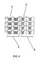
- Fig. 4 shows the structure of a possible base module.
- Reference number 5 and 6 indicate the so-called stacks of fuel cells (the stack is the assembly of elementary fuel cells supplied by the producers as the commercial product).
- the embodiment illustrated in fig. 4 is purely an example and must not be considered in any way as a limitation of the objects of the present invention.
- This embodiment comprises two sections for the base module, indicated by reference numerals 7 and 8, each one made respectively of 2 stacks in series, respectively of the type 5 and 6.
- fig. 4 is made of a number of elementary fuel cell which is half the number of the fuel cells of the stack of type 5.
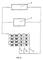
- fig. 5 shows the connection in parallel with the electrolyzers and the rectifier.
- the connection of the module may be carried out through the interrupters indicated by reference numerals 9, 10 and 11.
- the interrupter 11 When the interrupter 11 is activated, the voltage output of the module is maximum, and it is reduced to 80% and 70% respectively when interrupters 10 or 9 are activated.
- the voltage of the fuel cell system can be adjusted with time in order to make it compatible with that of the electrolyzers.
- the voltage of the latter may vary with time as a consequence of the continuous efficiency loss of the various components, such as the electrode, the catalytic activity of which undergoes a slow but constant decay. It is evident that the adjustment of the fuel cell stack voltage is of the intermittent type and is the more accurate the higher is the number of interrupters applied to the module. The need to use quantities of hydrogen which vary depending on the current fed to the electrolyzers is satisfied by sequentially connecting to the electrolyzers-rectifiers a certain number of modules in parallel.
- the activation of the interrupters which vary the number of inserted modules and the electric voltage of the modules themselves is effected by an iterative procedure which is performed by a computerised control and supervision system.
- An alternative embodiment of the present invention foresees that the variation of voltage of the modules be obtained by varying the pressure of the air fed to the fuel cells.
- Fig. 6 represents the behaviour as a function of the voltage of an elementary fuel cell, which, as aforementioned, is the base element of the stack. It must be noted that it is the air pressure, and not the hydrogen pressure, that influences in a remarkable way the voltage. Therefore, when the air pressure is varied, not necessarily also the hydrogen pressure must be varied. This situation is typically permitted by the membrane fuel cells which, if properly designed, are capable of undergoing air-hydrogen pressure differentials up to some bars.
Landscapes
- Chemical & Material Sciences (AREA)
- Engineering & Computer Science (AREA)
- Chemical Kinetics & Catalysis (AREA)
- Electrochemistry (AREA)
- Sustainable Development (AREA)
- Life Sciences & Earth Sciences (AREA)
- Manufacturing & Machinery (AREA)
- Sustainable Energy (AREA)
- General Chemical & Material Sciences (AREA)
- Metallurgy (AREA)
- Organic Chemistry (AREA)
- Materials Engineering (AREA)
- Electrolytic Production Of Non-Metals, Compounds, Apparatuses Therefor (AREA)
- Fuel Cell (AREA)
Abstract
Description
- The fuel cell is a static device which permits the direct conversion of chemical energy into electrical energy. As such, the fuel cell is not affected by the limitations of the Camot principle relating to thermal engines and is in fact characterised by high conversion efficiencies (50% or more with reference to the low heating value of the fed fuel). The most interesting types of fuel cells are those fed with air and hydrogen or a gas containing hydrogen, under pressure, usually from slightly above the atmospheric pressure to 3-5 bar. In particular, today attention is focused on the ion exchange polymeric membrane type, in view of its simplicity and for the potentially strong cost reduction. A type of design particularly suitable for membrane fuel cells is described in the
U.S. patent no. 5,482,792 . The technical development of the fuel cells today is extremely advanced, however their commercialisation is still far ahead due to the still high production costs, the lack of a reliable and efficient demonstrated design for the system of auxiliary components necessary to ensure the operation of the fuel cells, as well as of cost-effective availability of pure hydrogen or gas containing significant amount of hydrogen. This last problem is in fact overcome inside chemical complexes comprising electrochemical plants, typically chlor-alkali plants, chlorate electrolysis and hydrochloric acid electrolysis or refinery plants, which are characterised sometimes by the production of large amounts of by-product gases containing hydrogen. Electrochemical plants are particularly suitable for the integration with fuel cells, especially as the produced hydrogen is frequently very pure (chlor-alkali electrolysis, hydrochloric acid electrolysis) or can be easily purified (from traces of oxygen and chlorine, chlorate electrolysis). In addition, the electric energy produced by the fuel cells is typically of the direct type, same as the electric energy required by electrochemical plant electrolyzers. Therefore, in principle, it should be easy to integrate fuel cells into electrochemical plants, with the final result of substantially decreasing the overall consumption of electric power through the recovery of hydrogen. Conversely, in the case of chemical plants, the electric energy produced by the fuel cells should be converted into alternate current, which is the form of energy required by electric motors, heaters and other electrical apparatuses installed in these plants. The DC/AC converters of electric energy from direct to alternate current, known as inverters, are very expensive devices which make the assembly of the installation (fuel cells - connection piping - heat exchangers - inverter - electrical connection bus bars) economically disadvantageous with respect to the value of the produced electric energy. - These considerations take into account the interest shown since long towards the integration of fuel cells into electrochemical plants. An example of such an interest is the device described in the
U.S. patent no. 4,778,579 which is representative of the state of the art. This device, as many others described in other patents, foresees the use of an adjuster of voltage which is directed to make compatible the two voltages at the two ends of the electrolyzer and of the fuel cells. These voltages vary as the current varies and, at a constant current, with the varying of time, as described infig. 2 ofU.S. patent 4,778,579 . The voltage adjusters suitable for electric power of electrochemical plants are expensive devices which have thus the same inconveniences of the aforementioned inverters, which make the installation of the system based on fuel cells hardly economically attractive. -
US 4 310 605 discloses a fuel cell system comprising a fuel cell module.US 4 689 133 andFR 1 326 570 - It is the object of the present invention to provide a method for the direct integration of fuel cells in an electrochemical plant. By direct integration it is intended the connection of fuel cells to electrolyzers by means of bus bars without interposition of any voltage converter or adjuster or similar devices, used in the prior art.
- The invention will be now described making reference to the figures wherein:
-
Fig. 1 is a schematic view of a connection of the fuel cell-electrolyzers-rectifier-voltage adjuster of the prior art. -
Fig. 2 is a schematic view of a connection of the fuel cell-electrolyzers-rectifier according to the present invention, made in series. -
Fig. 3 is a schematic view of a connection of the fuel cell-electrolyzers-rectified according to the present invention, made in parallel. -
Fig. 4 is a schematic view of a fuel cell module. -
Fig. 5 is a schematic view of a connection in parallel of the fuel cell module offig. 4 with the electrolyzers-rectifier. -
Fig. 6 is a diagram showing the behaviour of an elementary fuel cell as a function of the voltage. - In the figures the same parts are indicated by the same reference numerals, in particular the fuel cell is identified by
reference numeral 1, the electrolyzer by 2, the rectifier by 3 and the voltage adjuster is indicated byreference numeral 4. -
Figure 2 schematises the series connection of fuel cells-electrolyzers-rectifier. This connection is characterised by a uniform electric current in the various points of the circuit and by an electric voltage required by the rectifier given by the difference between the electrolyzer voltage and fuel cell voltage. Conversely,fig. 3 schematises the parallel connection of the fuel cells to the electrolyzers-rectifier circuit. In this case the voltages of the three components are the same, while the current fed to the electrolyzers is given by the sum of the current output of the fuel cells and of the rectifier. Both systems offer advantages and present shortcomings which are in a certain way complementary, depending on the different applications. In particular: - the connection in series does not require any control of the current-output of the fuel cells as in fact the current is the one imposed by the rectifier. There is no need to control the voltage of the fuel cells to make it compatible with that of the electrolyzers as the balance is provided by the rectifier. From what said above it is clear that the connection in series is particularly simple as concerns the control system and is highly ductile in adjusting to the variations of the electric load. However, it is suitable only for circuits with substantially low electric current and requires, at the same power output, a higher number of fuel cells with respect to the connection in parallel.
- The connection in parallel is suitable for any range of electric current, even for the very high current typical of monopolar electrolyzers. Its control, although more complex than the system in series, is anyway still acceptable in the industrial scale. Further the connection in parallel permits to use a lower number of fuel cells with respect to the connection in series.
- The control of the overall output of the fuel cells may be achieved by using a suitable base module. The total fuel cell system is made of as many base modules as necessary to ensure complete utilisation of all the available hydrogen.
Fig. 4 shows the structure of a possible base module.Reference number 5 and 6 indicate the so-called stacks of fuel cells (the stack is the assembly of elementary fuel cells supplied by the producers as the commercial product). The embodiment illustrated infig. 4 is purely an example and must not be considered in any way as a limitation of the objects of the present invention. This embodiment comprises two sections for the base module, indicated byreference numerals 7 and 8, each one made respectively of 2 stacks in series, respectively of thetype 5 and 6. The stack of type 6 infig. 4 is made of a number of elementary fuel cell which is half the number of the fuel cells of the stack oftype 5. Supposing to use just one module offig. 4 ,fig. 5 shows the connection in parallel with the electrolyzers and the rectifier. In particular infig. 5 it can be seen how the connection of the module may be carried out through the interrupters indicated byreference numerals interrupter 11 is activated, the voltage output of the module is maximum, and it is reduced to 80% and 70% respectively wheninterrupters 10 or 9 are activated. With this structure of the module allowed by the typical dimensions of a stack of membrane fuel cells, the voltage of the fuel cell system can be adjusted with time in order to make it compatible with that of the electrolyzers. The voltage of the latter may vary with time as a consequence of the continuous efficiency loss of the various components, such as the electrode, the catalytic activity of which undergoes a slow but constant decay. It is evident that the adjustment of the fuel cell stack voltage is of the intermittent type and is the more accurate the higher is the number of interrupters applied to the module. The need to use quantities of hydrogen which vary depending on the current fed to the electrolyzers is satisfied by sequentially connecting to the electrolyzers-rectifiers a certain number of modules in parallel. As the voltage of the electrolyzers depends, besides the time of operation as above discussed, also on the intensity of the current fed thereto, the activation of the interrupters which vary the number of inserted modules and the electric voltage of the modules themselves is effected by an iterative procedure which is performed by a computerised control and supervision system. An alternative embodiment of the present invention foresees that the variation of voltage of the modules be obtained by varying the pressure of the air fed to the fuel cells.Fig. 6 represents the behaviour as a function of the voltage of an elementary fuel cell, which, as aforementioned, is the base element of the stack. It must be noted that it is the air pressure, and not the hydrogen pressure, that influences in a remarkable way the voltage. Therefore, when the air pressure is varied, not necessarily also the hydrogen pressure must be varied. This situation is typically permitted by the membrane fuel cells which, if properly designed, are capable of undergoing air-hydrogen pressure differentials up to some bars. - It must be understood that the above embodiment are not intended as a limitation of the invention.
Claims (9)
- Method for connecting fuel cells to electrochemical plants comprising electrolyzers equipped with electrically conductive bus bars and rectifiers, said electrolyzers forming hydrogen as a by-product, the fuel cells being fed with said hydrogen and air under pressure, characterised in that
said method is a direct connection of the fuel cell to the bus bars of the electrolyzers without any intermediate stage of voltage conversion or adjustment. - The method of claim 1 characterised in that said connection is of the series type.
- The method of claim 1 characterised in that said connection is of the parallel type.
- The method of the preceding claims characterised in that said fuel cells are assembled in modules made of sections.
- The method of claims 3 and 4 characterised in that it comprises sequentially inserting said modules to permit the use of said hydrogen in said fuel cells.
- The method of claims 3 and 4 characterised in that it comprises regulating the electric voltage of said fuel cells by sequentially inserting said module sections.
- The method of claims 5 or 6 characterised in that it comprises sequentially inserting said modules and said module sections by a computerised control and supervision system.
- The method of claims 3 and 4 characterised in that it comprises regulating the electric voltage of said fuel cells by varying the air pressure.
- The method of claims 5 or 6 characterised in that it comprises sequentially inserting said modules and varying the air pressure by means of a computerised control and supervision system.
Applications Claiming Priority (3)
| Application Number | Priority Date | Filing Date | Title |
|---|---|---|---|
| IT98MI000914A ITMI980914A1 (en) | 1998-04-29 | 1998-04-29 | METHOD FOR THE INTEGRATION OF FUEL CELLS WITH ELECTROCHEMICAL SYSTEMS |
| ITMI980914 | 1998-04-29 | ||
| PCT/EP1999/002772 WO1999056334A1 (en) | 1998-04-29 | 1999-04-23 | Method for the integration of fuel cells into electrochemical plants |
Publications (2)
| Publication Number | Publication Date |
|---|---|
| EP1082772A1 EP1082772A1 (en) | 2001-03-14 |
| EP1082772B1 true EP1082772B1 (en) | 2008-10-15 |
Family
ID=11379914
Family Applications (1)
| Application Number | Title | Priority Date | Filing Date |
|---|---|---|---|
| EP99920771A Expired - Lifetime EP1082772B1 (en) | 1998-04-29 | 1999-04-23 | Method for the integration of fuel cells into electrochemical plants |
Country Status (13)
| Country | Link |
|---|---|
| US (1) | US6423203B1 (en) |
| EP (1) | EP1082772B1 (en) |
| JP (1) | JP2002513199A (en) |
| KR (1) | KR100392156B1 (en) |
| CN (1) | CN1140003C (en) |
| AU (1) | AU736579B2 (en) |
| BR (1) | BR9910079A (en) |
| CA (1) | CA2327812C (en) |
| DE (1) | DE69939739D1 (en) |
| ES (1) | ES2317693T3 (en) |
| IT (1) | ITMI980914A1 (en) |
| TW (1) | TW431016B (en) |
| WO (1) | WO1999056334A1 (en) |
Families Citing this family (33)
| Publication number | Priority date | Publication date | Assignee | Title |
|---|---|---|---|---|
| US7138046B2 (en) * | 1996-06-06 | 2006-11-21 | World Hydrogen Energy Llc | Process for production of hydrogen from anaerobically decomposed organic materials |
| US6979507B2 (en) | 2000-07-26 | 2005-12-27 | Idatech, Llc | Fuel cell system controller |
| US6835481B2 (en) * | 2000-03-29 | 2004-12-28 | Idatech, Llc | Fuel cell system with load management |
| US6916564B2 (en) | 2000-05-31 | 2005-07-12 | Nuvera Fuel Cells, Inc. | High-efficiency fuel cell power system with power generating expander |
| US6610193B2 (en) * | 2000-08-18 | 2003-08-26 | Have Blue, Llc | System and method for the production and use of hydrogen on board a marine vessel |
| CA2440736A1 (en) | 2001-03-12 | 2002-09-19 | Stefan Fiedler | Method and device for producing oxygen |
| US6495025B2 (en) * | 2001-04-20 | 2002-12-17 | Aerovironment, Inc. | Electrochemical oxygen generator and process |
| US6893756B2 (en) * | 2002-04-30 | 2005-05-17 | General Motors Corporation | Lambda sensing with a fuel cell stack |
| US7422814B2 (en) * | 2003-01-29 | 2008-09-09 | Honda Motor Co., Ltd. | Fuel cell system |
| US7169497B2 (en) * | 2003-05-15 | 2007-01-30 | The Gillette Company | Electrochemical cells |
| US7052587B2 (en) * | 2003-06-27 | 2006-05-30 | General Motors Corporation | Photoelectrochemical device and electrode |
| KR20050054125A (en) * | 2003-12-04 | 2005-06-10 | 김학수 | An oxygen and nitrogen generating apparatus using an electrolysis device and a fuel cell |
| JP2007520860A (en) * | 2004-01-20 | 2007-07-26 | ネドスタック ホールディング ビー.ブイ. | Power plant with fuel cell |
| US7510640B2 (en) * | 2004-02-18 | 2009-03-31 | General Motors Corporation | Method and apparatus for hydrogen generation |
| US7459065B2 (en) * | 2004-02-18 | 2008-12-02 | General Motors Corporation | Hydrogen generator photovoltaic electrolysis reactor system |
| US7842428B2 (en) | 2004-05-28 | 2010-11-30 | Idatech, Llc | Consumption-based fuel cell monitoring and control |
| JP4899294B2 (en) * | 2004-06-10 | 2012-03-21 | 株式会社日立製作所 | Hydrogen fuel production system, hydrogen fuel production method, and hydrogen fuel production program |
| KR100853741B1 (en) * | 2004-06-18 | 2008-08-25 | 제너럴 모터즈 코오포레이션 | Systems and Subsystems for the Production and Use of Hydrogen |
| DE102005018291A1 (en) * | 2005-04-18 | 2006-10-19 | Varta Microbattery Gmbh | The fuel cell system |
| US20060246331A1 (en) * | 2005-04-29 | 2006-11-02 | Steinbroner Matthew P | Partitioned fuel cell stacks and fuel cell systems including the same |
| DE102006002470A1 (en) * | 2005-09-08 | 2007-03-15 | Airbus Deutschland Gmbh | Fuel cell system for supplying drinking water and oxygen has fuel cell and electrolysis cell configured so that power demand of electrolysis cell is covered by power output of fuel cell |
| CN101427307B (en) * | 2005-09-27 | 2012-03-07 | Lg电子株式会社 | Method and apparatus for encoding/decoding multi-channel audio signal |
| US20070184315A1 (en) * | 2006-02-09 | 2007-08-09 | Kelly Sean M | Control of fuel cell stack electrical operating conditions |
| US7887958B2 (en) * | 2006-05-15 | 2011-02-15 | Idatech, Llc | Hydrogen-producing fuel cell systems with load-responsive feedstock delivery systems |
| US8021525B2 (en) * | 2007-05-16 | 2011-09-20 | Commonwealth Scientific And Industrial Research Organisation | PEM water electrolysis for oxygen generation method and apparatus |
| KR100908029B1 (en) * | 2007-09-28 | 2009-07-15 | 삼성전기주식회사 | Fuel cell power generation system |
| DE102007052148A1 (en) | 2007-10-31 | 2009-05-07 | Robert Bosch Gmbh | Method for avoiding gaseous impurity inclusions in at least one gas space of a fuel cell during a standstill time and fuel cell with means for carrying out the method |
| WO2010056228A1 (en) * | 2008-11-17 | 2010-05-20 | Utc Power Corporation | Closed loop, fuel cell powered production of sodium chlorate |
| WO2010144850A1 (en) | 2009-06-12 | 2010-12-16 | Idatech, Llc | Systems and methods for independently controlling the operation of fuel cell stacks and fuel cell systems incorporating the same |
| KR101109631B1 (en) * | 2009-09-22 | 2012-01-31 | 주식회사 동주웰딩 | Manual carbon dioxide welding torch with welding cable connected by connecting ring |
| CN113235114B (en) * | 2021-05-10 | 2022-04-26 | 清华大学 | In-situ fuel cell combined heat and power supply system based on chlor-alkali byproduct hydrogen |
| US12283727B2 (en) | 2022-08-16 | 2025-04-22 | H2 Powertech, Llc | Hydrogen-producing fuel cell systems and methods of operating the same |
| WO2025129239A1 (en) * | 2023-12-19 | 2025-06-26 | Hysata Pty Ltd | Power supply for electro-synthetic or electro-energy cells |
Family Cites Families (9)
| Publication number | Priority date | Publication date | Assignee | Title |
|---|---|---|---|---|
| FR1326570A (en) * | 1962-03-30 | 1963-05-10 | Electro Chimie Soc D | Method for reducing energy consumption in an electrochemical operation |
| DE1421366A1 (en) | 1962-07-28 | 1968-10-31 | Esso Res & Engineering Company | Combined electrochemical process |
| US4084038A (en) * | 1974-12-19 | 1978-04-11 | Scragg Robert L | Electrical power generation and storage system |
| US4310605A (en) | 1980-09-22 | 1982-01-12 | Engelhard Minerals & Chemicals Corp. | Fuel cell system |
| JPS58130287A (en) * | 1982-01-27 | 1983-08-03 | Toshiba Corp | Electrolytic equipment |
| US4778579A (en) * | 1983-06-03 | 1988-10-18 | United Technologies Corporation | Method and apparatus for operating a fuel cell in combination with an electrochemical cell to produce a chemical product |
| JPS60169585A (en) * | 1984-02-15 | 1985-09-03 | Mitsui Toatsu Chem Inc | Salt electrolysis method |
| US4689133A (en) * | 1985-03-29 | 1987-08-25 | The Dow Chemical Company | Directly electrically coupled fuel cell-electrolysis cell system |
| GB9412073D0 (en) * | 1994-06-16 | 1994-08-03 | British Gas Plc | Method of operating a fuel cell |
-
1998
- 1998-04-29 IT IT98MI000914A patent/ITMI980914A1/en unknown
-
1999
- 1999-03-31 TW TW088105062A patent/TW431016B/en not_active IP Right Cessation
- 1999-04-23 ES ES99920771T patent/ES2317693T3/en not_active Expired - Lifetime
- 1999-04-23 US US09/674,312 patent/US6423203B1/en not_active Expired - Lifetime
- 1999-04-23 JP JP2000546408A patent/JP2002513199A/en active Pending
- 1999-04-23 WO PCT/EP1999/002772 patent/WO1999056334A1/en not_active Ceased
- 1999-04-23 AU AU38225/99A patent/AU736579B2/en not_active Ceased
- 1999-04-23 DE DE69939739T patent/DE69939739D1/en not_active Expired - Fee Related
- 1999-04-23 EP EP99920771A patent/EP1082772B1/en not_active Expired - Lifetime
- 1999-04-23 BR BR9910079-7A patent/BR9910079A/en not_active Application Discontinuation
- 1999-04-23 CA CA002327812A patent/CA2327812C/en not_active Expired - Fee Related
- 1999-04-23 CN CNB998055433A patent/CN1140003C/en not_active Expired - Fee Related
- 1999-04-23 KR KR10-2000-7011988A patent/KR100392156B1/en not_active Expired - Fee Related
Also Published As
| Publication number | Publication date |
|---|---|
| CN1140003C (en) | 2004-02-25 |
| KR20010071188A (en) | 2001-07-28 |
| DE69939739D1 (en) | 2008-11-27 |
| AU3822599A (en) | 1999-11-16 |
| ITMI980914A1 (en) | 1999-10-29 |
| CA2327812C (en) | 2008-10-14 |
| ES2317693T3 (en) | 2009-04-16 |
| BR9910079A (en) | 2000-12-26 |
| CN1298557A (en) | 2001-06-06 |
| EP1082772A1 (en) | 2001-03-14 |
| TW431016B (en) | 2001-04-21 |
| US6423203B1 (en) | 2002-07-23 |
| KR100392156B1 (en) | 2003-07-22 |
| CA2327812A1 (en) | 1999-11-04 |
| AU736579B2 (en) | 2001-08-02 |
| WO1999056334A1 (en) | 1999-11-04 |
| JP2002513199A (en) | 2002-05-08 |
Similar Documents
| Publication | Publication Date | Title |
|---|---|---|
| CA2327812C (en) | Method for the integration of fuel cells into electrochemical plants | |
| US6051125A (en) | Natural gas-assisted steam electrolyzer | |
| Kreuter et al. | Electrolysis: the important energy transformer in a world of sustainable energy | |
| EP3022335B1 (en) | Electrochemical cell and method for tuning an electrochemical cell stack | |
| US5543240A (en) | Fuel cell stack | |
| KR101926008B1 (en) | A control and operating method of power converter for power supply of hydrogen electrolytic device using solar energy | |
| US20210079544A1 (en) | Method of configuring a water electrolysis system | |
| US4467018A (en) | Manifold dielectric barrier for a fuel cell electrical power generation system | |
| US5041197A (en) | H2 /C12 fuel cells for power and HCl production - chemical cogeneration | |
| CN114761619A (en) | Electrolysis system for splitting water into hydrogen and oxygen and method for operating an electrolysis system | |
| Salzano et al. | Water vapor electrolysis at high temperature: systems considerations and benefits | |
| Harrison et al. | Electrolysis of water | |
| Nuttall | Conceptual design of large scale water electrolysis plant using solid polymer electrolyte technology | |
| CA2414226A1 (en) | Method for regulating the operation of fuel cell installations controlled according to heat and/or power requirement | |
| AU2020222397A1 (en) | Solar-powered water electrolyser | |
| EP1825551B1 (en) | Fuel cell with hydrogen internal recirculation | |
| CA2405380A1 (en) | Apparatus for water treatment having electrodeionization device | |
| US20040067397A1 (en) | Architected fuel cell system for modular application | |
| KR20240099082A (en) | Hybrid electrolysis system | |
| US20250202238A1 (en) | Methods and systems to provide electric power from solar energy equipment | |
| JP2024168801A (en) | Water electrolysis hydrogen production system | |
| Cisar et al. | PEM energy storage for solar aircraft | |
| Fathi et al. | A novel isolated DC/DC converter for fuel cell powered load | |
| JP2012029544A (en) | Voltage adjustment apparatus used for fuel cell, and method thereof | |
| NOUH et al. | Study on Proton Exchange Membrane Fuel Cells for Electric Vehicle Application |
Legal Events
| Date | Code | Title | Description |
|---|---|---|---|
| PUAI | Public reference made under article 153(3) epc to a published international application that has entered the european phase |
Free format text: ORIGINAL CODE: 0009012 |
|
| 17P | Request for examination filed |
Effective date: 20001011 |
|
| AK | Designated contracting states |
Kind code of ref document: A1 Designated state(s): BE CH DE DK ES FI FR GB IT LI NL SE |
|
| GRAP | Despatch of communication of intention to grant a patent |
Free format text: ORIGINAL CODE: EPIDOSNIGR1 |
|
| GRAS | Grant fee paid |
Free format text: ORIGINAL CODE: EPIDOSNIGR3 |
|
| GRAA | (expected) grant |
Free format text: ORIGINAL CODE: 0009210 |
|
| AK | Designated contracting states |
Kind code of ref document: B1 Designated state(s): BE CH DE DK ES FI FR GB IT LI NL SE |
|
| REG | Reference to a national code |
Ref country code: GB Ref legal event code: FG4D Ref country code: CH Ref legal event code: EP |
|
| REF | Corresponds to: |
Ref document number: 69939739 Country of ref document: DE Date of ref document: 20081127 Kind code of ref document: P |
|
| NLV1 | Nl: lapsed or annulled due to failure to fulfill the requirements of art. 29p and 29m of the patents act | ||
| REG | Reference to a national code |
Ref country code: ES Ref legal event code: FG2A Ref document number: 2317693 Country of ref document: ES Kind code of ref document: T3 |
|
| PG25 | Lapsed in a contracting state [announced via postgrant information from national office to epo] |
Ref country code: NL Free format text: LAPSE BECAUSE OF FAILURE TO SUBMIT A TRANSLATION OF THE DESCRIPTION OR TO PAY THE FEE WITHIN THE PRESCRIBED TIME-LIMIT Effective date: 20081015 Ref country code: FI Free format text: LAPSE BECAUSE OF FAILURE TO SUBMIT A TRANSLATION OF THE DESCRIPTION OR TO PAY THE FEE WITHIN THE PRESCRIBED TIME-LIMIT Effective date: 20081015 |
|
| PG25 | Lapsed in a contracting state [announced via postgrant information from national office to epo] |
Ref country code: DK Free format text: LAPSE BECAUSE OF FAILURE TO SUBMIT A TRANSLATION OF THE DESCRIPTION OR TO PAY THE FEE WITHIN THE PRESCRIBED TIME-LIMIT Effective date: 20081015 Ref country code: BE Free format text: LAPSE BECAUSE OF FAILURE TO SUBMIT A TRANSLATION OF THE DESCRIPTION OR TO PAY THE FEE WITHIN THE PRESCRIBED TIME-LIMIT Effective date: 20081015 |
|
| PLBE | No opposition filed within time limit |
Free format text: ORIGINAL CODE: 0009261 |
|
| STAA | Information on the status of an ep patent application or granted ep patent |
Free format text: STATUS: NO OPPOSITION FILED WITHIN TIME LIMIT |
|
| PG25 | Lapsed in a contracting state [announced via postgrant information from national office to epo] |
Ref country code: SE Free format text: LAPSE BECAUSE OF FAILURE TO SUBMIT A TRANSLATION OF THE DESCRIPTION OR TO PAY THE FEE WITHIN THE PRESCRIBED TIME-LIMIT Effective date: 20090115 |
|
| 26N | No opposition filed |
Effective date: 20090716 |
|
| REG | Reference to a national code |
Ref country code: CH Ref legal event code: PL |
|
| PG25 | Lapsed in a contracting state [announced via postgrant information from national office to epo] |
Ref country code: LI Free format text: LAPSE BECAUSE OF NON-PAYMENT OF DUE FEES Effective date: 20090430 Ref country code: CH Free format text: LAPSE BECAUSE OF NON-PAYMENT OF DUE FEES Effective date: 20090430 |
|
| PGFP | Annual fee paid to national office [announced via postgrant information from national office to epo] |
Ref country code: DE Payment date: 20091102 Year of fee payment: 11 |
|
| PGFP | Annual fee paid to national office [announced via postgrant information from national office to epo] |
Ref country code: GB Payment date: 20091102 Year of fee payment: 11 Ref country code: FR Payment date: 20091201 Year of fee payment: 11 |
|
| REG | Reference to a national code |
Ref country code: ES Ref legal event code: FD2A Effective date: 20090424 |
|
| PG25 | Lapsed in a contracting state [announced via postgrant information from national office to epo] |
Ref country code: ES Free format text: LAPSE BECAUSE OF NON-PAYMENT OF DUE FEES Effective date: 20090424 |
|
| GBPC | Gb: european patent ceased through non-payment of renewal fee |
Effective date: 20100423 |
|
| REG | Reference to a national code |
Ref country code: FR Ref legal event code: ST Effective date: 20101230 |
|
| PG25 | Lapsed in a contracting state [announced via postgrant information from national office to epo] |
Ref country code: DE Free format text: LAPSE BECAUSE OF NON-PAYMENT OF DUE FEES Effective date: 20101103 |
|
| PG25 | Lapsed in a contracting state [announced via postgrant information from national office to epo] |
Ref country code: IT Free format text: LAPSE BECAUSE OF NON-PAYMENT OF DUE FEES Effective date: 20090423 Ref country code: GB Free format text: LAPSE BECAUSE OF NON-PAYMENT OF DUE FEES Effective date: 20100423 |
|
| PG25 | Lapsed in a contracting state [announced via postgrant information from national office to epo] |
Ref country code: FR Free format text: LAPSE BECAUSE OF NON-PAYMENT OF DUE FEES Effective date: 20100430 |