EP1081776A2 - Method and arrangement for anticipating disengagement moment of battery package of battery-operated electronic device, and battery-operated electronic device - Google Patents
Method and arrangement for anticipating disengagement moment of battery package of battery-operated electronic device, and battery-operated electronic device Download PDFInfo
- Publication number
- EP1081776A2 EP1081776A2 EP00660146A EP00660146A EP1081776A2 EP 1081776 A2 EP1081776 A2 EP 1081776A2 EP 00660146 A EP00660146 A EP 00660146A EP 00660146 A EP00660146 A EP 00660146A EP 1081776 A2 EP1081776 A2 EP 1081776A2
- Authority
- EP
- European Patent Office
- Prior art keywords
- battery package
- identification members
- battery
- latch
- disengagement
- Prior art date
- Legal status (The legal status is an assumption and is not a legal conclusion. Google has not performed a legal analysis and makes no representation as to the accuracy of the status listed.)
- Withdrawn
Links
- 238000000034 method Methods 0.000 title claims abstract description 18
- 239000004020 conductor Substances 0.000 claims abstract description 8
- 239000000463 material Substances 0.000 description 9
- 229910052751 metal Inorganic materials 0.000 description 9
- 239000002184 metal Substances 0.000 description 9
- 238000005452 bending Methods 0.000 description 3
- 239000003990 capacitor Substances 0.000 description 3
- 230000009471 action Effects 0.000 description 1
- 238000004026 adhesive bonding Methods 0.000 description 1
- 239000000956 alloy Substances 0.000 description 1
- 229910045601 alloy Inorganic materials 0.000 description 1
- 230000008901 benefit Effects 0.000 description 1
- 230000008859 change Effects 0.000 description 1
- 210000000078 claw Anatomy 0.000 description 1
- 239000011248 coating agent Substances 0.000 description 1
- 238000000576 coating method Methods 0.000 description 1
- 238000004519 manufacturing process Methods 0.000 description 1
- 150000002739 metals Chemical class 0.000 description 1
- 239000012811 non-conductive material Substances 0.000 description 1
- 230000008569 process Effects 0.000 description 1
- 239000012858 resilient material Substances 0.000 description 1
Images



Classifications
-
- H—ELECTRICITY
- H01—ELECTRIC ELEMENTS
- H01M—PROCESSES OR MEANS, e.g. BATTERIES, FOR THE DIRECT CONVERSION OF CHEMICAL ENERGY INTO ELECTRICAL ENERGY
- H01M50/00—Constructional details or processes of manufacture of the non-active parts of electrochemical cells other than fuel cells, e.g. hybrid cells
- H01M50/20—Mountings; Secondary casings or frames; Racks, modules or packs; Suspension devices; Shock absorbers; Transport or carrying devices; Holders
- H01M50/247—Mountings; Secondary casings or frames; Racks, modules or packs; Suspension devices; Shock absorbers; Transport or carrying devices; Holders specially adapted for portable devices, e.g. mobile phones, computers, hand tools or pacemakers
-
- H—ELECTRICITY
- H01—ELECTRIC ELEMENTS
- H01M—PROCESSES OR MEANS, e.g. BATTERIES, FOR THE DIRECT CONVERSION OF CHEMICAL ENERGY INTO ELECTRICAL ENERGY
- H01M50/00—Constructional details or processes of manufacture of the non-active parts of electrochemical cells other than fuel cells, e.g. hybrid cells
- H01M50/20—Mountings; Secondary casings or frames; Racks, modules or packs; Suspension devices; Shock absorbers; Transport or carrying devices; Holders
- H01M50/202—Casings or frames around the primary casing of a single cell or a single battery
-
- H—ELECTRICITY
- H01—ELECTRIC ELEMENTS
- H01M—PROCESSES OR MEANS, e.g. BATTERIES, FOR THE DIRECT CONVERSION OF CHEMICAL ENERGY INTO ELECTRICAL ENERGY
- H01M50/00—Constructional details or processes of manufacture of the non-active parts of electrochemical cells other than fuel cells, e.g. hybrid cells
- H01M50/20—Mountings; Secondary casings or frames; Racks, modules or packs; Suspension devices; Shock absorbers; Transport or carrying devices; Holders
- H01M50/262—Mountings; Secondary casings or frames; Racks, modules or packs; Suspension devices; Shock absorbers; Transport or carrying devices; Holders with fastening means, e.g. locks
-
- H—ELECTRICITY
- H01—ELECTRIC ELEMENTS
- H01M—PROCESSES OR MEANS, e.g. BATTERIES, FOR THE DIRECT CONVERSION OF CHEMICAL ENERGY INTO ELECTRICAL ENERGY
- H01M6/00—Primary cells; Manufacture thereof
- H01M6/50—Methods or arrangements for servicing or maintenance, e.g. for maintaining operating temperature
- H01M6/5044—Cells or batteries structurally combined with cell condition indicating means
-
- Y—GENERAL TAGGING OF NEW TECHNOLOGICAL DEVELOPMENTS; GENERAL TAGGING OF CROSS-SECTIONAL TECHNOLOGIES SPANNING OVER SEVERAL SECTIONS OF THE IPC; TECHNICAL SUBJECTS COVERED BY FORMER USPC CROSS-REFERENCE ART COLLECTIONS [XRACs] AND DIGESTS
- Y02—TECHNOLOGIES OR APPLICATIONS FOR MITIGATION OR ADAPTATION AGAINST CLIMATE CHANGE
- Y02E—REDUCTION OF GREENHOUSE GAS [GHG] EMISSIONS, RELATED TO ENERGY GENERATION, TRANSMISSION OR DISTRIBUTION
- Y02E60/00—Enabling technologies; Technologies with a potential or indirect contribution to GHG emissions mitigation
- Y02E60/10—Energy storage using batteries
Definitions
- the invention relates to a method of anticipating a disengagement moment of a battery package of a battery-operated electronic device, in which method warning information is generated on disengagement of the battery package before electric connectors interconnecting the battery package and a housing of the device become detached from each other, and which warning information is generated by moving first identification members of the disengagement moment of the battery package from a first position to a second position with respect to second identification members of the disengagement moment of the battery package.
- the invention further relates to an arrangement for anticipating a disengagement moment of a battery package of a battery-operated electric device, which arrangement comprises first identification members of the disengagement moment of the battery package and second identification members of the disengagement moment of the battery package, the first identification members being arranged to be moved with respect to the second identification members between a first position and a second position such that when the first identification members are in the second position, warning information is arranged to be generated on the disengagement of the battery before electric connectors interconnecting the battery package and a housing of the device become detached from each other.
- the invention still further relates to a battery-operated electric device which comprises a housing of the device and a battery package to be detachably arranged in the housing, the device further comprising first identification members of the disengagement moment of the battery package and second identification members of the disengagement moment of the battery package, the first identification members being arranged to be moved with respect to the second identification members between a first position and a second position such that when the first identification members are in their second position, warning information is arranged to be generated on the disengagement of the battery before electric connectors interconnecting the battery package and the housing of the device become detached from each other.
- Batteries operating as a source of electrical power of battery-operated electronic devices such as mobile phones, PDA (Personal Digital Assistant) devices, portable computers or the like, are usually arranged in a battery package, which, in turn, is attached to the housing of the device such that the battery package can be disengaged from the device manually, without using any tools.
- the battery package is locked to the housing by a clasp or a latch which is appropriately moved to unlock the locking between the device and the battery. It is to be noted in this connection that hereinafter, battery-operated devices are called a device.
- a user of the device may, inadvertently or deliberately, detach the battery package without first turning off the device.
- the device in order for the functions that are being carried out in the device to be finished in a controlled manner before the power is disconnected, the device has to receive warning information about the battery package becoming disengaged before the device becomes physically disengaged from the electric connector.
- the warning information has to be received at least 5 ms before the disengagement so as to enable a controlled shutdown to take place.
- a known solution for anticipating the disengagement of the battery package is to arrange the battery package to be disengaged from the housing of a device with a sliding motion, the housing comprising, for example, springloaded identification members and corresponding metal contacts in the battery that follow the surface thereof.
- the metal contacts of the battery are of two different lengths, and when the battery package is being disengaged, the shorter contacts lose their contact with the identification members of the device earlier than the longer electric connectors, in which case the device receives an advance warning of the disengagement of the battery, being thus able to carry out a controlled shutdown.
- the battery package is openably detachable, and protruding contact members of two different lengths are arranged in the housing of the device or the battery package.
- the shorter contact members lose their contact earlier than the electric connectors, an advance warning of the battery becoming detached from the device being thus produced.
- WO-97/12414 discloses an application of this wherein a mechanical disengagement switch of the battery controls an electric switch used for electrically disconnecting the battery cells from the contact members arranged on the surface of the battery package; consequently, the short-circuit protection is improved if, for example, the battery is kept in a pocket among metal objects.
- a solution is also known wherein no warning of the disengagement of the battery is given in advance but large capacitors are arranged in the device whose charge is used for carrying out the shutdown.
- a disadvantage of the solution is the space-consuming additional capacitors which add to the weight of the device and increase component costs.
- An object of the invention is to provide a method and an arrangement for anticipating a disengagement moment of a battery package to avoid the above-mentioned drawbacks.
- a method of the invention is characterized in that the first identification members of the disengagement moment of the battery package are arranged in a latch of the battery package such that when the latch is moved in order to disengage the battery package from the housing of the device, the first identification members of the disengagement moment of the battery package are moved, said warning information being thus achieved.
- An arrangement of the invention is characterized in that the first identification members of the disengagement moment of the battery package are arranged in connection with a latch of the battery package such that when the latch is moved, the first identification members of the disengagement moment of the battery package move with respect to the second identification members of the battery package.
- An electric device of the invention is characterized in that the first identification members of the disengagement moment of the battery package are arranged in connection with a latch of the battery package such that when the latch is moved, the first identification members of the disengagement moment of the battery package move with respect to the second identification members of the battery package, said warning information being thus achieved.
- the idea underlying the invention is that the warning information on the disengagement moment of the battery package is generated by the first identification members of the disengagement moment of the battery package, the first identification members being integrated in the latch of the battery package, and by the second identification members of the disengagement moment of the battery package such that a motion to open the latch activated by a user in order to disengage the battery package from the housing of the device moves the first identification members of the disengagement moment of the battery package with respect to the second identification members of the disengagement moment of the battery package from the first position to the second position, thus causing the warning information to be generated as early as possible.
- the idea underlying a first preferred embodiment is that when the first identification members of the disengagement moment of the battery package are moved from their first position to the second position, they come into an electric contact with the second identification members of the disengagement moment of the battery package, whereby the warning information on the disengagement of the battery is caused by said electric contact.
- the idea underlying a second preferred embodiment is that the first identification members of the disengagement moment of the battery package are integrated in the spring element of the latch, a motion and/or deformation of the spring element when the latch is moved causing the warning information on the disengagement of the battery.
- the idea underlying a third preferred embodiment is that at least part of the latch of the battery package comprises an electrically conductive material, the first identification members of the disengagement moment of the battery package being integrated into said electrically conductive part.
- An advantage of the invention is that the warning of the disengagement of the battery package is produced as early as possible, i.e. immediately when the user moves the latch of the battery package to disengage the battery package.
- the arrangement of the invention is cost-efficient, mechanically durable, space-saving and reliable in use since it does not comprise any separate mechanical components. Neither does the arrangement comprise any large capacitors or similar space-consuming electric components that would cause component and assembly costs.
- the spring element can be mechanically assembled, so it is inexpensive to install.
- Figure 1 is a schematic, partly sectional top view of an embodiment of an arrangement of the invention.
- a first part 1 and a second part 2 of a device are arranged and locked together by a latch 3 in a manner known per se.
- the first part 1 of the device is the housing of the device, in which case the second part 2 of the device is the battery package of the device.
- a reverse arrangement is, of course, also possible wherein the first part 1 of the device is the battery package of the device and the second part 2 is the housing of the device.
- the latch 3 is shaped to enable ease of use; it is, for example, roughened or serrated, or, as in the embodiment shown by the figure, provided with a grip part 4 whereof a user of the device obtains an easy and reliable grip in order to use the latch 3.
- the latch 3 further comprises a tongue 5 which, forced by a spring element 7, is locked to a recess-like counter-part 6 of the tongue in the first part 1 of the device, and which simultaneously locks the first part 1 and the second part 2 of the device together.
- the tongue 5 is denoted by a broken line and the counter-part 6 of the tongue by a dotted broken line.
- the latch 3 is preferably manufactured from a plastic material.
- the spring element 7 is substantially immovably attached to the latch 3.
- the spring element 7 and the latch 3 can be attached mechanically by glueing or using another method known per se.
- the spring element 7, in turn, is manufactured from a suitably resilient material, typically from metal or alloy of metals.
- the spring element 7 comprises four branch-like protruding parts, a first and a second branch thereof being arranged as return springs 8, and a third and a fourth branch being arranged as first identification members 9 of a disengagement moment of the battery package.
- an unbroken line denotes a position of the return springs 8 of the sprig element 7 in the direction of which the spring force of the return springs 8 affects, a corresponding first position 15 of the first identification members 9 of the disengagement moment of the battery package, and, further, a corresponding position of the latch 3.
- the element 7 forces the tongue 5 of the latch 3 into the counter-part 6 in the first part 1 of the device, whereby the first part 1 and the second part 2 of the device are locked together, and the first identification members 9 of the battery package are in their first position 15 with respect to second identification members 10 of the battery package, in which first position 15 the first identification members 9 of the battery package do not come into contact with the second identification members 10 of the battery package.
- the second identification members 10 are placed on a circuit board 12, but also other placement solutions known per se to one skilled in art are feasible.
- the user of the device wants to detach the battery package from the housing of the device, he or she first moves the latch 3 in the direction indicated by arrow S in order to release the tongue 5 from the counter-part 6. Consequently, the return springs 8 of the spring element 7 yield in direction S and the free ends of the return spring 8 slide away from each other on a counter-surface 14 and the first identification members 9 of the battery package slide to a second position 16 such that they come into contact with the second identification members 10.
- the second position 16 of the first identification members 9 and the corresponding position of the latch 3 and the spring element 7 are shown in the figure by a densely-dashed broken line.
- the contact between the first and the second identification members 9, 10 generates information on the basis of which the device receives an advance warning of the disengagement of the battery and starts to shut down ongoing functions in the device. If the generation of the warning information is based on the establishment of an electric contact between the second identification members of the disengagement moment of the battery, at least the first identification members 9 of the disengagement moment of the battery must naturally be made of an electrically conductive material. The rest of the spring element 7 may be made of a substantially electrically non-conductive material. Hence, the process of shutting down the functions is provided with as much time as possible since the warning of the disengagement of the battery is produced immediately in connection with a first action to be carried out to disengage the battery.
- Other locking devices than the latch 3 can, of course, be arranged between the housing of the device and the battery package in a manner known per se, but the only way to detach the battery package from the housing is to move the latch 3 from its first position to the second position.
- Figure 2a is a schematic side view of an embodiment of the latch of the battery shown in Figure 1
- Figure 2b is a partly sectional view of the same embodiment of the latch as shown in the direction of the first identification members 9.
- the second part 2 of the device i.e. the battery package in the present embodiment, in which the latch 3 is arranged
- Figure 2b lacks the second part 2.
- the grip part 4 In order to make the latch 3 easier to handle, it is provided with the grip part 4 such that the user of the device is provided with a reliable grip with his or her finger to change the position of the latch 3.
- the tongue 5 formed in the latch 3 matches the counter-part 6 provided in the first part 1 of the device.
- the shape of the tongue 5 and the counter-part 6 thereof may naturally be another shape known per se than that shown in Figure 2a.
- the latch 3 and the spring element 7 are attached to each other such that a protruding part 11 provided in the spring element 7 is arranged in a close-fit attachment groove formed in the latch 3, whereby said protruding part 11 penetrates into the material of the latch 3 and attaches the spring 7 substantially immovably to the latch 3. Ends 17 of the first identification members 9 of the disengagement moment of the battery lean against a sliding surface 18.
- the ends 17 of the first identification members 9 slide and come into contact with the second identification members 10 of the disengagement moment of the battery arranged in the first part 1 of the device, and the warning information of the disengagement of the battery is thus generated.
- the identification members 9, 10 of the disengagement moment of the battery are thus arranged in different parts of the device: the first identification members 9 are arranged in the second part 2 of the device, i.e. in the battery package of the device, and the second identification members 10 are arranged in the first part 1 of the device, i.e. in the housing of the device. From the second identification members 10, the information on the disengagement of the battery package can be readily transmitted to ongoing functions in the device.
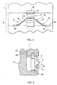
- Figure 3 is a schematic, partly sectional top view of an embodiment of a second arrangement of the invention.
- the first part 1 of the device is the battery package of the device and the second part 2 is the housing of the device.
- the latch 3 is arranged in the second part 2 of the device and it is similar in structure and operation to the one described in connection with the figures discussed above.
- a spring element 7' arranged in the latch 3 now comprises two branches that operate both as a return spring of the latch 3 and as first identification members 9' of the disengagement moment of the battery package.
- the second identification members 10 of the disengagement moment of the battery package are, in turn, arranged on the sliding surface 14 of the free ends of the spring element 7'.
- Figure 4 is a schematic, partly sectional side view of an embodiment of the latch of the battery according to Figure 3.
- the latch 3 and the first identification members 9' of the disengagement moment of the battery attached thereto are arranged in the second part 2 of the device, as are the second identification members 10 of the disengagement moment of the battery. Since the second part 2 of the device is its housing, the information on the disengagement of the battery can be readily and simply transmitted from the identification members 9', 10 of the disengagement moment of the battery to the functions of the device in manners known per se to one skilled in the art.
- the information on the disengagement of the battery package can be transmitted to the functions of the device by separate identification members arranged in the battery package which, however, are not shown in the figure for the sake of simplicity.
- the first part 1 and the second part 2 of the device are detachably attached to each other by one or more attachment members 17, which attachment member 17 can, for example, be a pin or a claw formed in the second part to be slid into the groove formed in the second part, or another corresponding attachment solution known per se.
- the attachment member 17 can be located at any suitable point of the interface surface of the first part 1 and the second part 2 although it is placed extremely close to the latch 3 in the embodiment shown by the figure.
- the essential point is, however, that the first part 1 and the second part 2 of the device cannot be detached from each other without moving the latch 3. Electrical power from the battery package to the functions of the device is transmitted via electric connectors 19.
- FIG 5 is a schematic, partly sectional top view of a third embodiment of an arrangement of the invention.
- the embodiment of the invention shown in the figure is in its relevant parts similar to the embodiment shown in Figure 3 and 4, but in their first position 15, the first identification members 9' of the disengagement moment of the battery come into contact with the second identification members 10 of the disengagement moment of the battery, and, correspondingly, in the second position 16, they do not come into contact with said second identification members 10.
- the warning information on the disengagement of the battery is thus generated when the contact between the first identification members 9' and the second identification members 10 of the disengagement moment of the battery is broken.
- the same principle can also be applied in connection with the four-branched spring element 7 according to Figure 1.
- FIG. 6 is a schematic, partly sectional side view of a fourth embodiment of a latch of the battery package of the invention.
- a latch 3' arranged in the second part 2 of the device attaches, by means of its claw-shaped tongue 5', behind a protruding part 20 of a counter-part 6' arranged in the first part 1, thus interlocking said first and second parts.
- the latch 3' When the latch 3' is to be opened, it is first pressed in the direction indicated by arrow P, and next, the tongue 5' is released from the counter-part 6' by moving the latch 3', still being pressed down, in the direction indicated by arrow S from its first position 15 to its second position 16.
- the latch 3' is made of a material which is resistant to repeated bending, which materials property, combined with the shape of the latch 3', enables the locking to be implemented without a separate spring element.
- the attachment of the latch 3' to the second part 2 of the device is implemented resiliently.
- the material of the latch 3' is electrically conductive.
- the material can be plastic, metal or the like.
- the lower surface of the latch 3' sliding against the sliding surface 18 operates as first identification members 9" of the disengagement moment of the battery, and when the latch 3' is being opened, the lower surface of the latch 3' slides and comes into contact with the second identification members 10 of the disengagement moment of the battery package arranged on the sliding surface 18. Said contact of the identification members 9", 10 generates the information on the disengagement of the battery.
- a separate spring element is used in connection with a latch made of an at least partly electrically conductive material.
- Figure 7 is a schematic top view of an embodiment of the latch of the battery package according to Figure 6.
- An electric contact is established between the second identification members 10 of the disengagement moment of the battery package when the latch 3' slides over them.
- the second identification members 10 can be, for example, spring contacts, whereby the clearance between the latch 3' and the sliding surface 18 can be greater.
- the structure of the latch 3' can also be partially electrically conductive such that only the first identification members 9" of the disengagement moment of the battery package are made of an electrically conductive material.
- FIG 8 is a schematic sectional side view of a fifth embodiment of the latch of the battery package of the invention.
- a latch 3" of the battery package is made of a resilient plastic material, and the first identification members 9" of the disengagement moment of the battery package are arranged on the surface of a tongue 5" of the latch 3".
- the first identification members 9" of the disengagement moment of the battery package are manufactured by, for example, coating with a thin metal layer, attaching a metal layer onto the surface at issue in some other manner, mixing an electrically conductive filling material in the surface material, or manufacturing the identification members from electrically conductive plastic.
- the entire latch 3" can also be manufactured as an integrated component from a suitable, electrically conductive material. In an embodiment of the invention, the latch 3" is substantially entirely made of metal.
- the second identification members 10 of the disengagement moment of the battery package are arranged in a counter-part 6" of the tongue 5" located in the first part 1 of the device such that when the tongue 5" is arranged in the counter-part 6", the first and the second identification members 9", 10 come into contact with each other.
- the second identification members 10 are preferably implemented as spring contacts.
- the first part 1 and the second part 2 of the device are detached from each other by bending the latch 3" in the direction indicated by arrow B, whereby the latch 3" bends, particularly at its bending part 21, when the tongue 5" is released from its counter-part 6".
- the contact between the first identification members 9" and the second identification members 10 of the disengagement moment of the battery arranged in the latch 3" is broken, the warning information on the disengagement of the battery package thus being generated.
Landscapes
- Chemical & Material Sciences (AREA)
- Chemical Kinetics & Catalysis (AREA)
- Electrochemistry (AREA)
- General Chemical & Material Sciences (AREA)
- Engineering & Computer Science (AREA)
- Manufacturing & Machinery (AREA)
- Life Sciences & Earth Sciences (AREA)
- Biophysics (AREA)
- Computer Hardware Design (AREA)
- Battery Mounting, Suspending (AREA)
- Secondary Cells (AREA)
Abstract
Description
Claims (26)
- A method of anticipating a disengagement moment of a battery package of a battery-operated electronic device, in which method warning information is generated on disengagement of the battery package before electric connectors (19) interconnecting the battery package and a housing of the device become detached from each other, and which warning information is generated by moving first identification members (9, 9', 9") of the disengagement moment of the battery package from a first position (15) to a second position (16) with respect to second identification members (10) of the disengagement moment of the battery package, characterized in that the first identification members (9, 9', 9") of the disengagement moment of the battery package are arranged in a latch (3, 3', 3") of the battery package such that when the latch (3, 3', 3") is moved in order to disengage the battery package from the housing of the device, the first identification members (9, 9', 9") of the disengagement moment of the battery package are moved, said warning information being thus achieved.
- A method as claimed in claim 1, characterized in that when the first identification members (9, 9', 9") of the disengagement moment of the battery package are moved in their second position (16), they come into contact with the second identification members (10) of the disengagement moment of the battery package.
- A method as claimed in claim 1, characterized in that when the first identification members (9, 9") of the disengagement moment of the battery package are moved from their first position (15) to the second position (16), they lose the contact with the second identification members (10) of the disengagement moment of the battery package.
- A method as claimed in any one of the preceding claims, characterized in that the first identification members (9, 9') of the disengagement moment of the battery package are integrated into a spring element (7, 7') of the latch (3).
- A method as claimed in any one of the preceding claims, characterized in that the latch (3', 3") comprises an electrically conductive material, and that the first identification members (9") of the disengagement moment of the battery package are integrated into the electrically conductive part of the latch (3', 3").
- A method as claimed in any one of the preceding claims, characterized in that the latch (3, 3', 3") is arranged in the battery package.
- A method as claimed in any one of claims 1 to 4, characterized in that the latch (3, 3', 3") is arranged in the housing of the device.
- A method as claimed in any one of the preceding claims, characterized in that the device comprises a first part (1) and a second part (2), one of the parts (1, 2) being the housing of the device and the other being the battery package of the device, and that the first identification members (9, 9', 9") of the disengagement moment of the battery package and the second identification members (10) of the disengagement moment of the battery package are arranged in the same part (1, 2) of the device.
- A method as claimed in any one of claims 1 to 7, characterized in that the device comprises a first part (1 ) and a second part (2), one of the parts (1, 2) being the housing of the device and the other being the battery package of the device, and that the first identification members (9, 9', 9") of the disengagement moment of the battery package and the second identification members (10) of the disengagement moment of the battery package are arranged in different parts (1, 2) of the device.
- An arrangement for anticipating a disengagement moment of a battery package of a battery-operated electric device, which arrangement comprises first identification members (9, 9', 9") of the disengagement moment of the battery package and second identification members (10) of the disengagement moment of the battery package, the first identification members (9, 9', 9") being arranged to be moved with respect to the second identification members (10) between a first position (15) and a second position (16) such that when the first identification members (9, 9', 9") are in the second position (16), warning information is arranged to be generated on the disengagement of the battery before electric connectors (19) interconnecting the battery package and a housing of the device become detached from each other, characterized in that the first identification members (9, 9', 9") of the disengagement moment of the battery package are arranged in connection with a latch (3, 3', 3") of the battery package such that when the latch (3, 3', 3") is moved, the first identification members (9, 9', 9") of the disengagement moment of the battery package move with respect to the second identification members (10) of the battery package.
- An arrangement as claimed in claim 10, characterized in that in their second position (16), the first identification members (9, 9') of the disengagement moment of the battery package come into contact with the second identification members (10) of the disengagement moment of the battery package.
- An arrangement as claimed in claim 10, characterized in that in their first position (15), the first identification members (9', 9") of the disengagement moment of the battery package come into contact with the second identification members (10) of the disengagement moment of the battery package.
- An arrangement as claimed in any one of claims 10 to 12, characterized in that the first identification members (9, 9') of the disengagement moment of the battery package are integrated into a spring element (7, 7') of the latch (3, 3').
- An arrangement as claimed in any one of the preceding claims, characterized in that the latch (3', 3") comprises an electrically conductive material, and that the first identification members (9, 9') of the disengagement moment of the battery package are integrated into the electrically conductive part of the latch (3', 3").
- An arrangement as claimed in claim 13, characterized in that the spring element (7) of the latch (3) comprises substantially four branches, a first and a second branch thereof being arranged to operate as a return spring (8) of the latch (3), and a third and a fourth branch being arranged to operate as the first identification members (9) of the disengagement moment of the battery package.
- An arrangement as claimed in claim 13, characterized in that the spring element (7') comprises substantially two branches that are arranged to operate as the return spring of the latch (3) and as the first identification members (9') of the disengagement moment of the battery package.
- An arrangement as claimed in any one of claims 10 to 16, characterized in that the latch (3, 3', 3") is arranged in the battery package of the device.
- An arrangement as claimed in any one of claims 10 to 16, characterized in that the latch (3, 3', 3") is arranged in the housing of the device.
- An arrangement as claimed in any one of claims 10 to 18, characterized in that the first identification members (9, 9', 9") and the second identification members (10) of the disengagement moment of the battery package are integrated in identification and temperature contacts of the battery package.
- An arrangement as claimed in any one of claims 10 to 19, characterized in that the device comprises a first part (1 ) and a second part (2), one of the parts (1, 2) being the housing of the device and the other being the battery package of the device, and that the first identification members (9, 9', 9") of the disengagement moment of the battery package and the second identification members (10) of the disengagement moment of the battery package are arranged in the same part (1, 2) of the device.
- An arrangement as claimed in any one of claims 10 to 19, characterized in that the device comprises a first part (1) and a second part (2), one of the parts (1, 2) being the housing of the device and the other being the battery package of the device, and that the first identification members (9, 9', 9") of the disengagement moment of the battery package and the second identification members (10) of the disengagement moment of the battery package are arranged in different parts (1, 2) of the device.
- A battery-operated electric device which comprises a housing of the device and a battery package to be detachably arranged in the housing, the device further comprising first identification members (9, 9', 9") of a disengagement moment of the battery package and second identification members (10) of the disengagement moment of the battery package, the first identification members (9, 9', 9") being arranged to be moved with respect to the second identification members (10) between a first position (15) and a second position (16) such that when the first identification members (9, 9', 9") are in their second position (16), warning information is arranged to be generated on the disengagement of the battery before electric connectors (19) interconnecting the battery package and the housing of the device become detached from each other, characterized in that the first identification members (9, 9', 9") of the disengagement moment of the battery package are arranged in connection with a latch (3, 3', 3") of the battery package such that when the latch (3, 3', 3") is moved, the first identification members (9, 9', 9") of the disengagement moment of the battery package move with respect to the second identification members (10) of the battery package, said warning information being thus achieved.
- A battery-operated electric device as claimed in claim 22, characterized in that the first identification members (9, 9', 9") of the disengagement moment of the battery package and the second identification members (10) of the battery package are arranged in the housing of the device.
- A battery-operated electric device as claimed in claim 22, characterized in that the first identification members (9, 9', 9") of the disengagement moment of the battery package and the second identification members (10) of the disengagement moment of the battery package are arranged in the battery package.
- A battery-operated electric device as claimed in claim 22, characterized in that the first identification members (9, 9', 9") of the disengagement moment of the battery package are arranged in the housing of the device and the second identification members (10) of the disengagement moment of the battery package are arranged in the battery package.
- A battery-operated electric device as claimed in claim 22, characterized in that the first identification members (9, 9', 9") of the disengagement moment of the battery package are arranged in the battery package and the second identification members (10) of the disengagement moment of the battery package are arranged in the housing of the device.
Applications Claiming Priority (2)
| Application Number | Priority Date | Filing Date | Title |
|---|---|---|---|
| FI991860 | 1999-09-01 | ||
| FI19991860A FI19991860A7 (en) | 1999-09-01 | 1999-09-01 | Method and arrangement for predicting the moment of battery pack disconnection of a battery-powered electronic device and battery-powered electronic device |
Publications (2)
| Publication Number | Publication Date |
|---|---|
| EP1081776A2 true EP1081776A2 (en) | 2001-03-07 |
| EP1081776A3 EP1081776A3 (en) | 2003-05-14 |
Family
ID=8555229
Family Applications (1)
| Application Number | Title | Priority Date | Filing Date |
|---|---|---|---|
| EP00660146A Withdrawn EP1081776A3 (en) | 1999-09-01 | 2000-08-31 | Method and arrangement for anticipating disengagement moment of battery package of battery-operated electronic device, and battery-operated electronic device |
Country Status (3)
| Country | Link |
|---|---|
| US (1) | US6602635B1 (en) |
| EP (1) | EP1081776A3 (en) |
| FI (1) | FI19991860A7 (en) |
Cited By (1)
| Publication number | Priority date | Publication date | Assignee | Title |
|---|---|---|---|---|
| EP1912429A2 (en) | 2006-10-10 | 2008-04-16 | Samsung Electronics Co., Ltd. | Battery locking device and electronic appliance adopting the same |
Families Citing this family (7)
| Publication number | Priority date | Publication date | Assignee | Title |
|---|---|---|---|---|
| JP2004158242A (en) * | 2002-11-05 | 2004-06-03 | Alps Electric Co Ltd | Power supply for electronic equipment |
| DE102004043823A1 (en) * | 2004-09-10 | 2006-03-16 | Robert Bosch Gmbh | Device for locking a power tool with a battery pack |
| TWI286212B (en) * | 2004-11-03 | 2007-09-01 | Mediatek Inc | Battery detecting system |
| TW201137681A (en) * | 2010-04-28 | 2011-11-01 | Giga Byte Tech Co Ltd | Mouse |
| CN102279619B (en) * | 2010-06-10 | 2016-05-18 | 鸿富锦精密工业(深圳)有限公司 | Electronic equipment |
| KR102756274B1 (en) * | 2019-03-06 | 2025-01-17 | 주식회사 엘지에너지솔루션 | System and method for detecting a hardware anomaly of a battery system controller |
| CN112200987A (en) * | 2020-10-16 | 2021-01-08 | 郭芳芳 | Semiconductor package based structural body with warning function |
Family Cites Families (7)
| Publication number | Priority date | Publication date | Assignee | Title |
|---|---|---|---|---|
| DE9015923U1 (en) | 1990-11-22 | 1992-03-19 | Otto Bock Orthopädische Industrie Besitz- und Verwaltungs-Kommanditgesellschaft, 3408 Duderstadt | accumulator |
| JPH04133349U (en) | 1991-05-31 | 1992-12-11 | 日本電気株式会社 | Battery pack terminal protection structure |
| US5293109A (en) * | 1992-09-28 | 1994-03-08 | Motorola, Inc. | Early recognition battery disconnect |
| US5733673A (en) * | 1995-06-07 | 1998-03-31 | Norand Corporation | Method and apparatus to detect imminent battery removal in a portable electronic device |
| US5578391A (en) * | 1995-09-25 | 1996-11-26 | Motorola, Inc. | Battery pack having a disconnect switch circuit |
| US5868794A (en) * | 1997-04-08 | 1999-02-09 | Survivalink Corporation | AED and battery pack with anticipatory battery disengagement detection |
| US6141223A (en) * | 1998-05-08 | 2000-10-31 | Smk Manufacturing, Inc. | Battery assembly for supplying power to an integrated circuit |
-
1999
- 1999-09-01 FI FI19991860A patent/FI19991860A7/en unknown
-
2000
- 2000-08-31 EP EP00660146A patent/EP1081776A3/en not_active Withdrawn
- 2000-08-31 US US09/652,337 patent/US6602635B1/en not_active Expired - Lifetime
Cited By (2)
| Publication number | Priority date | Publication date | Assignee | Title |
|---|---|---|---|---|
| EP1912429A2 (en) | 2006-10-10 | 2008-04-16 | Samsung Electronics Co., Ltd. | Battery locking device and electronic appliance adopting the same |
| EP1912429A3 (en) * | 2006-10-10 | 2008-07-16 | Samsung Electronics Co., Ltd. | Battery locking device and electronic appliance adopting the same |
Also Published As
| Publication number | Publication date |
|---|---|
| FI19991860L (en) | 2001-03-01 |
| US6602635B1 (en) | 2003-08-05 |
| EP1081776A3 (en) | 2003-05-14 |
| FI19991860A7 (en) | 2001-03-02 |
Similar Documents
| Publication | Publication Date | Title |
|---|---|---|
| US11901570B2 (en) | Battery pack | |
| KR930001527B1 (en) | Battery housing with integral latch and positive displacement apparatus | |
| JP4589935B2 (en) | Portable electronic devices and accessories | |
| US8817476B2 (en) | Apparatus, add-on module, and a system comprising a host apparatus and an add-on module | |
| US5382167A (en) | Magnetically secured temporary electrical connector | |
| US7173818B2 (en) | Coupling structure for a handheld electronic device and a back cartridge thereof | |
| US20030022633A1 (en) | Mobile phone with battery latch | |
| CA2231573A1 (en) | Battery pack having a disconnect switch circuit | |
| US7642744B2 (en) | Charger and battery combination with retention arms and mating members | |
| US6602635B1 (en) | Method and arrangement for anticipating disengagement moment of battery package of battery-operated electronic device, and battery-operated electronic device | |
| US6554640B1 (en) | Radio communication equipment having a floating connector | |
| CN101990022A (en) | Press key assembly and portable electronic device applying same | |
| JPH1050428A (en) | Connector for ic card | |
| EP0952630A3 (en) | Electrical connector for flat flexible circuitry | |
| AU3720797A (en) | Radiotelephone having a combination fastener and electrical connector | |
| AU702700B2 (en) | Case for microcircuit card reader | |
| KR100887613B1 (en) | Connector for memory card and portable terminal having the same | |
| US6454589B1 (en) | I/O connector with improved button mechanism | |
| US5626980A (en) | Contact block in a battery pack having snap in features | |
| CN110571893A (en) | Chargers, Wearables and Charging Systems | |
| US20230018206A1 (en) | Dual real time clock (rtc) battery holder and method of manufacture | |
| TW201017958A (en) | Electronic device | |
| JP2556643Y2 (en) | Small electrical equipment switch | |
| JP4152171B2 (en) | Holder and contact terminal protection structure | |
| TWI373870B (en) | Battery structure and portable electronic device therewith |
Legal Events
| Date | Code | Title | Description |
|---|---|---|---|
| PUAI | Public reference made under article 153(3) epc to a published international application that has entered the european phase |
Free format text: ORIGINAL CODE: 0009012 |
|
| AK | Designated contracting states |
Kind code of ref document: A2 Designated state(s): AT BE CH CY DE DK ES FI FR GB GR IE IT LI LU MC NL PT SE |
|
| AX | Request for extension of the european patent |
Free format text: AL;LT;LV;MK;RO;SI |
|
| RAP1 | Party data changed (applicant data changed or rights of an application transferred) |
Owner name: NOKIA CORPORATION |
|
| PUAL | Search report despatched |
Free format text: ORIGINAL CODE: 0009013 |
|
| AK | Designated contracting states |
Designated state(s): AT BE CH CY DE DK ES FI FR GB GR IE IT LI LU MC NL PT SE |
|
| AX | Request for extension of the european patent |
Extension state: AL LT LV MK RO SI |
|
| AKX | Designation fees paid | ||
| REG | Reference to a national code |
Ref country code: DE Ref legal event code: 8566 |
|
| STAA | Information on the status of an ep patent application or granted ep patent |
Free format text: STATUS: THE APPLICATION IS DEEMED TO BE WITHDRAWN |
|
| 18D | Application deemed to be withdrawn |
Effective date: 20030902 |