EP1081731A1 - Key protection structure for an electronic apparatus - Google Patents
Key protection structure for an electronic apparatus Download PDFInfo
- Publication number
- EP1081731A1 EP1081731A1 EP00117808A EP00117808A EP1081731A1 EP 1081731 A1 EP1081731 A1 EP 1081731A1 EP 00117808 A EP00117808 A EP 00117808A EP 00117808 A EP00117808 A EP 00117808A EP 1081731 A1 EP1081731 A1 EP 1081731A1
- Authority
- EP
- European Patent Office
- Prior art keywords
- shutter
- switch
- covering
- switch operation
- operation hole
- Prior art date
- Legal status (The legal status is an assumption and is not a legal conclusion. Google has not performed a legal analysis and makes no representation as to the accuracy of the status listed.)
- Granted
Links
- 230000000694 effects Effects 0.000 description 8
- 238000010586 diagram Methods 0.000 description 5
- 230000006870 function Effects 0.000 description 5
- 230000001105 regulatory effect Effects 0.000 description 5
- 230000003213 activating effect Effects 0.000 description 3
- 239000004020 conductor Substances 0.000 description 1
- 229920003023 plastic Polymers 0.000 description 1
- 230000035807 sensation Effects 0.000 description 1
Images





Classifications
-
- H—ELECTRICITY
- H01—ELECTRIC ELEMENTS
- H01H—ELECTRIC SWITCHES; RELAYS; SELECTORS; EMERGENCY PROTECTIVE DEVICES
- H01H13/00—Switches having rectilinearly-movable operating part or parts adapted for pushing or pulling in one direction only, e.g. push-button switch
- H01H13/70—Switches having rectilinearly-movable operating part or parts adapted for pushing or pulling in one direction only, e.g. push-button switch having a plurality of operating members associated with different sets of contacts, e.g. keyboard
-
- H—ELECTRICITY
- H01—ELECTRIC ELEMENTS
- H01H—ELECTRIC SWITCHES; RELAYS; SELECTORS; EMERGENCY PROTECTIVE DEVICES
- H01H9/00—Details of switching devices, not covered by groups H01H1/00 - H01H7/00
- H01H9/20—Interlocking, locking, or latching mechanisms
- H01H9/28—Interlocking, locking, or latching mechanisms for locking switch parts by a key or equivalent removable member
- H01H9/287—Interlocking, locking, or latching mechanisms for locking switch parts by a key or equivalent removable member wherein the operating part is made inaccessible or more difficult to access by a lid, cover or guard, e.g. lockable covers
-
- H—ELECTRICITY
- H01—ELECTRIC ELEMENTS
- H01H—ELECTRIC SWITCHES; RELAYS; SELECTORS; EMERGENCY PROTECTIVE DEVICES
- H01H11/00—Apparatus or processes specially adapted for the manufacture of electric switches
- H01H11/0006—Apparatus or processes specially adapted for the manufacture of electric switches for converting electric switches
-
- H—ELECTRICITY
- H01—ELECTRIC ELEMENTS
- H01H—ELECTRIC SWITCHES; RELAYS; SELECTORS; EMERGENCY PROTECTIVE DEVICES
- H01H27/00—Switches operated by a removable member, e.g. key, plug or plate; Switches operated by setting members according to a single predetermined combination out of several possible settings
Definitions
- the present invention relates to a key protection structure for an electronic apparatus including an electronic control device such as a timer or a temperature controller.
- an operation section 200 is disposed in the front face.
- the operation section 200 is configured by a switch unit (not shown) and a front cover 209.
- the switch unit comprises first, second, and third switches 210, 211, and 212, and a printed circuit board (not shown) on which electronic parts are mounted and a conductor pattern (not shown) is formed.
- a first switch operation hole 213 and an arcuate display window 213A, a second switch operation hole 214, and a third switch operation hole 215 are formed in a face 209a of the front cover 209.
- the second and third switch operation holes 214 and 215 have rectangular display windows 214A and 215A, respectively.
- a setting knob member 216 disposed on an operation shaft (not shown) of the first switch 210 is placed so as to forward protrude from the face 209a of the front cover 209.
- a setting knob member 217 disposed on an operation shaft (not shown) of the second switch 211 is placed so as to forward protrude from the face 209a of the front cover 209.
- a setting knob member 218 disposed on an operation shaft (not shown) of the third switch 212 is placed so as to forward protrude from the face 209a of the front cover 209.
- the setting knob members 216, 217, and 218 are not disposed in the first, second, and third switches 210, 211, and 212, and cross grooves 219, 220, and 221 may be disposed in the centers of knobs (not shown) of the first, second, and third switches 210, 211, and 212, respectively.
- the cross groove 219 of the first switch 210 is operably positioned in the first switch operation hole 213 of the front cover 209.
- the cross groove 220 of the second switch 211 is operably positioned in the second switch operation hole 214.
- the cross groove 221 of the third switch 212 is operably positioned in the third switch operation hole 215.
- a tool (not shown) having an operation portion (not shown) in which an engaging projection (not shown) of a cross shape is formed at the tip end is used.
- the operation portion of the tool is inserted into the first switch operation hole 213 (the second switch operation hole 214 or the third switch operation hole 215) of the front cover 209.
- the cross engaging projection of the operation portion is engaged with the cross groove 219 (220 or 221) of the first switch 210 (the second switch 211 or the third switch 212).
- the tool is rotated, so that the first switch 210 (the second switch 211 or the third switch 212) is rotated to change the setting.
- the setting knob member 216 of the first switch 210 is placed in the first switch operation hole 213 so as to forward protrude from the face 209a of the front cover 209.
- the setting knob member 217 of the second switch 211 relating to the second switch operation hole 214, and the setting knob member 218 of the third switch 212 relating to the third switch operation hole 215 are placed in a similar manner as the setting knob member 216. Therefore, any one can rotate the setting knob member 216, 217, or 218 to change preset value, irrespective of whether the contents of the work are those allowed to only a specific worker or not. Consequently, such an apparatus has a problem in that it is impossible to prevent a preset value from being intentionally changed.
- the cross groove 219 of the first switch 210 is positioned in the first switch operation hole 213 of the front cover 209
- the cross groove 220 of the second switch 211 is positioned in the second switch operation hole 214
- the cross groove 221 of the third switch 212 is positioned in the third switch operation hole 215. Therefore, the cross grooves 219, 220, and 221 can be easily visually recognized from the outside.
- any one can rotate the setting knob member 216, 217, or 218 to change preset value, irrespective of whether the contents of the work are those allowed to only a specific worker or not. Consequently, also such an apparatus has a problem in that it is impossible to prevent a preset value from being intentionally changed.
- the invention has been conducted in view of the above-discussed problems. It is an object of the invention to provide a key protection structure for an electronic apparatus which can prevent a preset value of a switch from being intentionally changed by the user or the like, and which, even when no software exists, can ensure a key protection function by a simple structure.
- a key protection structure for an electronic apparatus of a first aspect of the invention in an electronic apparatus in which a switch operation hole corresponding to a switch operation portion of each of switches that are incorporated in a main unit of the apparatus is disposed in the apparatus main unit, and the switch is activated by operating the switch operation portion through the switch operation hole, the switch operation portion is covered by covering means in which covering is cancelled only by a special tool.
- the switch operation portion is covered by the covering means in which the covering is cancelled only by a special tool, whereby the switch can be locked (key-protected) so as not to be externally operated.
- the preset value can be prevented from being intentionally changed by a person who do not have the special tool, such as the user. Even an electronic apparatus in which software for key protection is not prepared can be provided with a key protection function by a simple structure.
- some apparatuses have an input terminal or a switch for activating key protection, and realize a key protection function on the basis of an input operation performed on the terminal or the switch.
- such an apparatus requires a dedicated input terminal or switch.
- key protection is performed by covering the whole of a front portion by a cover. In this case, there arises a disadvantage that the cover may not be removed away. According to the invention, it is possible to obtain a structure which can eliminate such a disadvantage, and realize also space saving.
- the key protection level can be changed depending on the kind of the special tool, i.e., a dedicated key.
- a key protection structure for an electronic apparatus of a second aspect of the invention is configured so that, in the key protection structure for an electronic apparatus of the first aspect of the invention, the covering of the switch operation portion by the covering means is performed on one or more of the switches which is required to be covered.
- the same effects as the above-described effects of the first aspect of the invention can be attained. Since the covering of the switch operation portion by the covering means is performed only on one or more of the switches which is required to be covered, moreover, the switches can be classified so as to prevent a field worker from erroneously operate the switches. As a result, an operation section which is easy for the worker to operate can be obtained.
- the structure comprises: a shutter which covers the switch operation hole and cancels the covering; a shutter operation portion which is disposed in the shutter and with which a tool shutter operation portion of a special tool is to be disengeably engaged; and a shutter operation hole which is disposed in the apparatus main unit, which corresponds to the shutter operation portion of the shutter, and into which the special tool is to be inserted.
- the tool shutter operation portion of the special tool is inserted into the shutter operation hole, and the tool shutter operation portion is then engaged with the shutter operation portion of the shutter. Thereafter, the shutter is activated by operating the special tool. The shutter is then moved immediately above the switch to close the switch operation hole, whereby the switch can be locked (key-protected) so as not to be externally operated.
- the preset value can be prevented from being intentionally changed by a person who do not have the special tool, such as the user.
- the switches can be classified so as to prevent a field worker from erroneously operate the switches.
- an operation section which is easy for the worker to operate can be obtained.
- an electronic apparatus in which software for key protection is not prepared can be provided with a key protection function by a simple structure.
- an input terminal or a switch for activating key protection is required.
- an input terminal or a switch can be eliminated.
- key protection is performed by covering the whole of a front portion of an electronic apparatus by a cover, there arises a disadvantage that the cover may not be removed away.
- the key protection level can be changed depending on the kind of the special tool, i.e., a dedicated key.
- a key protection structure for an electronic apparatus of a fourth aspect of the invention is configured so that, in the key protection structure for an electronic apparatus of the third aspect of the invention, the structure comprises positioning means for positioning the shutter at either of a covering position where the shutter covers the switch operation hole, and a covering canceling position where the shutter does not cover the switch operation hole.
- the shutter can be positioned at either of a covering position where the shutter covers the switch operation hole, and a covering canceling position where the shutter separates from the switch operation hole, by the positioning means.
- a key protection structure for an electronic apparatus of a fifth aspect of the invention is configured so that, in the key protection structure for an electronic apparatus of the third aspect of the invention, the structure comprises moving distance limiting means for limiting a moving distance of the shutter.
- the same effects as the above-described effects of the third aspect of the invention can be attained. Furthermore, the moving distance of the shutter can be regulated by the moving distance regulating means.
- a key protection structure for an electronic apparatus of a sixth aspect of the invention is configured so that, in the key protection structure for an electronic apparatus of the third aspect of the invention, the shutter operation portion is an engaging portion which has a special shape, and with which the tool shutter operation portion of the special tool is to be disengeably engaged.
- the shutter operation portion is an engaging portion which has a special shape, and with which the tool shutter operation portion of the special tool is to be disengeably engaged. Even when an ordinary tool such as a hexagonal wrench is used, therefore, the shutter cannot be activated (rotated). As a result, the switch can be locked (key-protected) so as not to be externally operated.
- a key protection structure for an electronic apparatus of a seventh aspect of the invention in an electronic apparatus in which an operation section consisting of a switch unit and a front cover is disposed in a main unit of the apparatus, plural switches are disposed by using the switch unit as a base, a switch operation hole corresponding to a switch operation portion of each of the switches is disposed in the front cover, and the switch is activated by operating the switch operation portion through the switch operation hole, the shutter is configured by forming a covering portion at a tip end of a shaft, the covering portion being perpendicular to the shaft, and forming an engaging portion with which a tool shutter operation portion of a special tool is to be disengeably engaged, in a tip end face of the shaft, plural shutter holding cylinders are disposed in a face of the base, a shutter operation hole which corresponds to the engaging portion of each shutter, and into which the special tool is to be inserted is disposed in the front cover, the shutter is disposed on the base while the shaft is
- the tool shutter operation portion of the special tool when setting of the switch is once ended, the tool shutter operation portion of the special tool is inserted into the shutter operation hole, and the tool shutter operation portion is then engaged with the engaging portion of the shutter. Thereafter, the shutter is activated by operating the special tool. The covering portion is then moved immediately above the switch to close the switch operation hole, whereby the switch can be locked (key-protected) so as not to be externally operated.
- the preset value can be prevented from being intentionally changed by a person who do not have the special tool, such as the user.
- the switches can be classified so as to prevent a field worker from erroneously operate the switches.
- the operation section which is easy for the worker to operate can be obtained.
- an electronic apparatus in which software for key protection is not prepared can be provided with a key protection function by a simple structure.
- an input terminal or a switch for activating key protection is required.
- such an input terminal or a switch can be eliminated.
- key protection is performed by covering the whole of a front portion of an electronic apparatus by a cover. In this case, there arises a disadvantage that the cover may not be removed away. According to the invention, it is possible to obtain a structure which can eliminate such a disadvantage and realize also space saving. Furthermore, the key protection level can be changed depending on the kind of the special tool, i.e., a dedicated key.
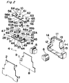
- An electronic apparatus A is generally configured by: a case 1; a cover 2; an internal apparatus 4 which is accommodated in a housing 3 consisting of the case 1 and the cover 2; and a front cover 10.
- the housing 3 and the front cover 10 constitute the main unit of the apparatus.
- the internal apparatus 4 is generally configured by: first and second terminal blocks 5 and 6; a switch unit 7; and a circuit board unit 9 in which many electronic parts are mounted on a printed circuit board 8.
- the case 1 comprises the case body 1-1 of a substantially quadrangular shape, and a unit mounting portion 11 is formed on the front face of the case body 1-1.
- a first terminal block mounting portion 12 is formed on a side wall 1A of the case 1, and a second terminal block mounting portion 13 is formed on a side wall 1B of the case 1.
- the switch unit 7 and the front cover 10 are mounted on the unit mounting portion 11 of the case 1.
- the first terminal block 5 is mounted on the first terminal block mounting portion 12, and the second terminal block 6 is mounted on the second terminal block mounting portion 13.
- the circuit board unit 9 is mounted inside the case 1, and the cover 2 is mounted on the case 1, thereby constituting the electronic apparatus A.
- an operation section 400 (Fig. 1) consisting of the switch unit 7 and the front cover 10 is disposed.
- Terminal blocks 401 and 402 are disposed on both the sides across the operation section 400, respectively.
- a rail engaging portion 403 is disposed on the rear face of the electronic apparatus A.
- the switch unit 7 comprises a transparent base 14. As shown in Fig. 4, first, second, and third switch holding holes 16, 17, and 18 are disposed in a face 14a of the base 14.
- a switch body 21A of a switch 21 such as a time setting switch is rotatably inserted into and passed through the first switch holding hole 16.
- a switch body 22A of a switch 22 such as a range setting switch is rotatably inserted into and passed through the second switch holding hole 17.
- a switch body 23A of a switch 23 such as a mode changeover switch is rotatably inserted into and passed through the third switch holding hole 18.
- a hook 27 is formed in the periphery of each of the switch bodies 21A, 22A, and 23A.
- the switch bodies 21A, 22A, and 23A are fittingly inserted into the first, second, and third switch holding holes 16, 17, and 18, the hooks 27 are slidingly in contact with the peripheries of the first, second, and third switch holding holes 16, 17, and 18, respectively.
- Flange-like knobs 28, 29, and 30 are formed on ends of the switch bodies 21A, 22A, and 23A, respectively.
- Cross grooves 31, 32, and 33 serving as switch operation portions with which a special tool is to be engaged are formed at the centers of the knobs 28, 29, and 30, respectively.
- first, second, and third shutter holding cylinders 34, 35, and 36 are disposed in the face 14a of the base 14 so as to pass threrethrough.
- cantilever-like tongue pieces 37 are respectively formed at positions which are opposed to each other.
- a projection 38 is disposed on the inside of the tip end portion of each of the tongue pieces 37.
- a first shutter 40 for covering the first switch is rotatably inserted into and passed through the first shutter holding cylinder 34.
- a second shutter 41 for covering the second switch is rotatably inserted into and passed through the second shutter holding cylinder 35.
- a third shutter 42 for covering the third switch is rotatably inserted into and passed through the third shutter holding cylinder 36.
- each of the first, second, and third shutters 40, 41, and 42 is configured by disposing a covering portion 44 at the tip end of a shaft 43 so as to be perpendicular to the shaft 43.
- the tip end portion of each covering portion 44 is made wider.
- a polygonal (heptagonal) engaging recess 45 serving as a shutter operation portion is formed in the tip end face of the shaft 43.
- Two pairs of grooves 46a and 46b elongating in the axial direction of the shaft 43 are formed at positions of the shaft 43 which are opposed to each other, respectively.
- Each of the first, second, and third shutters 40, 41, and 42 constitutes covering means in which covering is cancelled only by a special tool.
- the first shutter 40 is disposed in the base 14 so that the shaft 43 of the shutter is inserted into and passed through the first shutter holding cylinder 34.
- the second shutter 41 is disposed in the base 14 so that the shaft 43 of the shutter is inserted into and passed through the second shutter holding cylinder 35.
- the third shutter 42 is disposed in the base 14 so that the shaft 43 of the shutter is inserted into and passed through the third shutter holding cylinder 36.
- the projections 38 of the tongue pieces 37 are disengeably engaged with the grooves 46a of the shaft 43, respectively.
- Light emitting diode accommodating portions 47 and 48 which protrude to the front side are formed in both the side areas of the base 14, respectively.
- An engaging projection 49 is disposed in each of the ends of the base 14.
- First, second, and third variable resistors which are not shown, and light emitting diodes (not shown) are mounted on the mounting face of the printed circuit board 8 on which electronic parts are mounted.
- the front cover 10 has a cover body 10A. Attachment legs 55 and 56 protrude from both end sides of the rear face of the cover body 10A. Engaging holes 57 are formed in the attachment legs 55 and 56. In the face 10a of the cover body 10A, formed are a first switch operation hole 58, an arcuate display window 58A centered at the first switch operation hole 58, a second switch operation hole 59, and a third switch operation hole 60.
- the second and third switch operation holes 59 and 60 have rectangular display windows 59A and 60A, respectively.
- a transparent plastic plate or the like is fixed to the display windows 58A, 59A, and 60A.
- First, second, and third shutter operation holes 61, 62, and 63 which are circular are formed in the face 10a of the cover body 10A.
- Light emitting diode display windows 64 and 65 are disposed in the face 10a of the cover body 10A so as to be positioned in both the ends of the face.
- the base 14 is attached to the rear side of the front cover 10 while engaging the engaging projections 49 on both the ends with the engaging holes 57 of the attachment legs 55 and 56 of the front cover 10.
- the first, second, and third shutters 40, 41, and 42 are slidingly in contact with the rear side of the cover body 10A the front cover 10, whereby the shutters are prevented from slipping off.
- the center cross groove 31 of the knob 28 of the first switch 21 is positioned in the first switch operation hole 58.
- a numeral(s) (not shown) for displaying the time and indicated on the knob 28 is positioned in the display window 58A.
- the center cross groove 32 of the knob 29 of the second switch 22 is positioned in the second switch operation hole 59.
- a range setting symbol (not shown) indicated on the knob 29 is positioned in the display window 59A.
- the center cross groove 33 of the knob 30 of the third switch 23 is positioned in the third switch operation hole 60.
- a symbol (not shown) indicated on the knob 30 is positioned in the display window 60A.
- the polygonal engaging portion 45 of the first shutter 40 is positioned in the first shutter operation hole 61.
- the polygonal engaging portion 45 of the second shutter 41 is positioned in the second shutter operation hole 62.
- the polygonal engaging portion 45 of the third shutter 42 is positioned in the third shutter operation hole 63.
- the light emitting diode accommodating portions 47 and 48 are positioned in the light emitting diode display windows 64 and 65, respectively.
- the end portion of the switch body 21A of the first switch 21 is coupled with a movable member of a first volume disposed on the mounting face of the printed circuit board 8.
- the end portion of the switch body 22A of the second switch 22 is coupled with a movable member of a second volume
- the end portion of the switch body 23A of the third switch 23 is coupled with a movable member of a third volume.
- the light emitting diodes mounted on the mounting face of the printed circuit board 8 are accommodated in the light emitting diode accommodating portions 47 and 48 of the base 14, respectively.
- Figs. 6 and 7 show a lock key 70 serving as a special tool.
- the lock key 70 has a pen-like shape.
- a tool switch operation portion 71 having a cross engaging projection 71a is disposed in one end portion (upper end portion) of the lock key 70.
- a tool shutter operation portion 72 having an engaging projection 72a of a polygonal prism-like shape (heptagonal prism-like shape) is disposed in the other end portion (lower end portion) of the lock key 70.
- a clip 73 is attached to the lock key 70.
- a hole 74 for attaching an anti-loss chain is disposed in the basal portion of the clip 73.
- the electronic apparatus A which is configured as described above is attached to a rail member (not shown) by using the rail engaging portion 403 on the rear face.
- the worker can set the electronic apparatus A by using the lock key 70 which is possessed by the worker.
- the tool switch operation portion 71 of the lock key 70 is inserted into the first switch operation hole 58 of the front cover 10.
- the cross engaging projection 71a of the tool switch operation portion 71 is engaged with the center cross groove 31 of the knob 28 of the first switch 21.
- the lock key 70 is then rotated, whereby the first switch 21 is rotated to change the preset time.
- the preset time is displayed by a numeral (s) in the display window 58A.
- the tool switch operation portion 71 of the lock key 70 is inserted into the second switch operation hole 59 of the front cover 10.
- the cross engaging projection 71a of the tool switch operation portion 71 is engaged with the center cross groove 32 of the knob 29 of the second switch 22.
- the lock key 70 is then rotated, whereby the second switch 22 is rotated to set the range.
- the set range is displayed by the range setting symbol in the display window 59A.
- the tool switch operation portion 71 of the lock key 70 is inserted into the third switch operation hole 60 of the front cover 10.
- the cross engaging projection 71a of the tool switch operation portion 71 is engaged with the center cross groove 33 of the knob 30 of the third switch 23.
- the lock key 70 is then rotated, whereby the third switch 23 is rotated to set the output mode.
- the set output mode is displayed by a symbol in the display window 60A.
- the tool shutter operation portion 72 of the lock key 70 is inserted into the first shutter operation hole 61.
- the polygonal engaging projection 72a of the tool shutter operation portion 72 is engaged with the engaging recess 45 of the first shutter 40.
- the lock key 70 is rotated in the right direction E in Fig. 8, whereby the first shutter 40 is rotated as shown in Figs. 9A to 10B.
- the covering portion 44 is therefore moved immediately above the first switch 21 to close the first switch operation hole 58, whereby the first switch 21 is locked (key-protected) so as not to be externally operated (see Figs. 11A and 11B).
- the tool shutter operation portion 72 of the lock key 70 is inserted into the second shutter operation hole 62.
- the polygonal engaging projection 72a of the tool shutter operation portion 72 is engaged with the engaging recess 45 of the second shutter 41.
- the lock key 70 is rotated in the right direction E in Fig. 8, whereby the second shutter 41 is rotated from the state of Fig. 9A to that of Fig. 10A.
- the covering portion 44 is therefore moved immediately above the second switch 22 to close the second switch operation hole 59, whereby the second switch 22 is locked (key-protected) so as not to be externally operated (see Figs. 11A and 11B).
- the tool shutter operation portion 72 of the lock key 70 is inserted into the third shutter operation hole 63.
- the polygonal engaging projection 72a of the tool shutter operation portion 72 is engaged with the engaging recess 45 of the third shutter 42.
- the lock key 70 is rotated in the right direction E in Fig. 8, whereby the third shutter 42 is rotated from the state of Fig. 9A to that of Fig. 10A.
- the covering portion 44 is therefore moved immediately above the engaging recess 45 of the third switch 23 to close the third switch operation hole 60, whereby the third switch 23 is locked (key-protected) so as not to be externally operated (see Figs. 11A and 11B).
- a lock canceling position by the first, second, or third shutter 40, 41, or 42 positioning is performed while the projections 38 of the tongue pieces 37 are disengeably engaged with the pair of opposing grooves 46a of the shaft 43 of the first, second, or third shutter 40, 41, or 42, respectively.
- the first, second, or third shutter 40, 41, or 42 is rotated from the state of Fig. 9A to that of Fig. 10A in order to conduct locking, however, the projections 38 of the tongue pieces 37 are disengaged from the opposing grooves 46a of the shaft 43, and then engaged with the other pair of grooves 46b.
- the locking by the first, second, or third shutter 40, 41, or 42 is positioned and clicking sensation in the rotational direction is produced. Therefore, the grooves 46a and 46b of the shafts 43 of the first, second, and third shutters 40, 41, and 42, and the projections 38 of the tongue pieces 37 constitute positioning means.
- a first recess 66 which has a fan-like shape and is centered at the first shutter operation hole 61
- a second recess 67 which has a fan-like shape and is centered at the second shutter operation hole 62
- a third recess 68 which has a fan-like shape and is centered at the third shutter operation hole 63 may be formed in the rear side of the face 10a of the cover body 10A.
- the covering portion 44 of the first shutter 40 is housed in the first recess 66 so as to be swingable within a predetermined angular range
- the covering portion 44 of the second shutter 41 is housed in the second recess 67 so as to be swingable within a predetermined angular range
- the covering portion 44 of the third shutter 42 is housed in the third recess 68 so as to be swingable within a predetermined angular range.
- the tool shutter operation portion 72 of the lock key 70 is inserted into the first shutter operation hole 61 (the second or third shutter operation hole 62 or 63).
- the shutter operation portion 72 is then engaged with the engaging recess 45 of the first shutter 40 (the second or third shutter 41 or 42).
- the lock key 70 is rotated, so that the first shutter 40 (the second or third shutter 41 or 42) is rotated.
- the covering portion 44 is therefore moved immediately above the first switch 21 (the second or third switch 22 or 23) to close the first switch operation hole 58 (the second or third switch operation hole 59 or 60), whereby the first switch 21 (the second or third switch 22 or 23) can be locked (key-protected) so as not to be externally operated.
- the covering operation by a shutter may be performed only on one of the first, second, and third switches 21, 22, and 23 which is necessary to be covered.
- the first switch 21 maybe subjected to the covering operation by first shutter 40, and the covering operation by a shutter may not be performed on the second and third switches 22 and 23.
- the first, second, and third switches 21, 22, and 23 are classified into those which are to be subjected to the covering operation by a shutter, and those which are not to be subjected to the covering operation by a shutter, it is possible to obtain an operation section which is prevented from being erroneously operated by a field worker, and which is easy for the worker to operate.
- Each of the engaging recesses 45 serving as shutter operation portions is formed as a heptagonal recess, and the shutter operation portion 72 of the lock key 70 is formed as the engaging projection 72a of a heptagonal prism-like shape.
- the shapes are not restricted to them.
- the engaging recesses 45 has a shape of a cross groove, a triangular, rectangular, or pentagonal recess, or the like.
- the engaging recesses 45 serving as shutter operation portions may have any shape as far as the shape is in conformity with the shutter operation portion 72 of the lock key 70.
- the engaging recesses 45 serving as shutter operation portions may be formed as engaging projections 45' of a polygonal prism-like shape, and the shutter operation portion 72 of the lock key 70 may be formed as a polygonal engaging recess 72a' so as to be engageable with the engaging projections 45'.
- Figs. 13 and 14 show this example.
- the first, second, and third shutters 40, 41, and 42 independently perform the covering operation and the operation of canceling the covering on the first, second, and third switch operation holes 58, 59, and 60.
- all of or two of the first, second, and third shutters 40, 41, and 42 may be linked with each other via a gear train, and, when one of the shutters is driven, the other shutter(s) may be activated (rotated) with being interlocked with the operation of the shutter.
Landscapes
- Switch Cases, Indication, And Locking (AREA)
- Push-Button Switches (AREA)
- Fittings On The Vehicle Exterior For Carrying Loads, And Devices For Holding Or Mounting Articles (AREA)
- Lock And Its Accessories (AREA)
- Electrophonic Musical Instruments (AREA)
- Transmitters (AREA)
Abstract
Description
- The present invention relates to a key protection structure for an electronic apparatus including an electronic control device such as a timer or a temperature controller.
- In a conventional electronic apparatus, as shown in Fig. 15, an
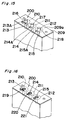
operation section 200 is disposed in the front face. Theoperation section 200 is configured by a switch unit (not shown) and afront cover 209. The switch unit comprises first, second, andthird switches - In a
face 209a of thefront cover 209, a firstswitch operation hole 213 and anarcuate display window 213A, a secondswitch operation hole 214, and a thirdswitch operation hole 215 are formed. The second and thirdswitch operation holes rectangular display windows - In the first
switch operation hole 213, asetting knob member 216 disposed on an operation shaft (not shown) of thefirst switch 210 is placed so as to forward protrude from theface 209a of thefront cover 209. In the secondswitch operation hole 214, asetting knob member 217 disposed on an operation shaft (not shown) of thesecond switch 211 is placed so as to forward protrude from theface 209a of thefront cover 209. In the thirdswitch operation hole 215, asetting knob member 218 disposed on an operation shaft (not shown) of thethird switch 212 is placed so as to forward protrude from theface 209a of thefront cover 209. - When setting is to be performed through the first, second, or
third switch setting knob member - In the
operation section 200 used in another conventional electronic apparatus, as shown in Fig. 16, thesetting knob members third switches cross grooves third switches cross groove 219 of thefirst switch 210 is operably positioned in the firstswitch operation hole 213 of thefront cover 209. Thecross groove 220 of thesecond switch 211 is operably positioned in the secondswitch operation hole 214. Thecross groove 221 of thethird switch 212 is operably positioned in the thirdswitch operation hole 215. - When setting is to be performed through the first, second, or
third switch switch operation hole 214 or the third switch operation hole 215) of thefront cover 209. The cross engaging projection of the operation portion is engaged with the cross groove 219 (220 or 221) of the first switch 210 (thesecond switch 211 or the third switch 212). Thereafter, the tool is rotated, so that the first switch 210 (thesecond switch 211 or the third switch 212) is rotated to change the setting. - In the former one of the conventional electronic apparatuses described above, for example, the
setting knob member 216 of thefirst switch 210 is placed in the firstswitch operation hole 213 so as to forward protrude from theface 209a of thefront cover 209. Also thesetting knob member 217 of thesecond switch 211 relating to the secondswitch operation hole 214, and thesetting knob member 218 of thethird switch 212 relating to the thirdswitch operation hole 215 are placed in a similar manner as thesetting knob member 216. Therefore, any one can rotate thesetting knob member - In the latter one of the conventional electronic apparatuses, the
cross groove 219 of thefirst switch 210 is positioned in the firstswitch operation hole 213 of thefront cover 209, thecross groove 220 of thesecond switch 211 is positioned in the secondswitch operation hole 214, and thecross groove 221 of thethird switch 212 is positioned in the thirdswitch operation hole 215. Therefore, thecross grooves setting knob member - The invention has been conducted in view of the above-discussed problems. It is an object of the invention to provide a key protection structure for an electronic apparatus which can prevent a preset value of a switch from being intentionally changed by the user or the like, and which, even when no software exists, can ensure a key protection function by a simple structure.
- In order to attain the object, according to a key protection structure for an electronic apparatus of a first aspect of the invention, in an electronic apparatus in which a switch operation hole corresponding to a switch operation portion of each of switches that are incorporated in a main unit of the apparatus is disposed in the apparatus main unit, and the switch is activated by operating the switch operation portion through the switch operation hole, the switch operation portion is covered by covering means in which covering is cancelled only by a special tool.
- According to this configuration, when setting of the switch is once ended, the switch operation portion is covered by the covering means in which the covering is cancelled only by a special tool, whereby the switch can be locked (key-protected) so as not to be externally operated.
- Therefore, the preset value can be prevented from being intentionally changed by a person who do not have the special tool, such as the user. Even an electronic apparatus in which software for key protection is not prepared can be provided with a key protection function by a simple structure.
- Conventionally, some apparatuses have an input terminal or a switch for activating key protection, and realize a key protection function on the basis of an input operation performed on the terminal or the switch. In this case, such an apparatus requires a dedicated input terminal or switch. According to the invention, such an input terminal or a switch can be eliminated. In some electronic apparatuses, key protection is performed by covering the whole of a front portion by a cover. In this case, there arises a disadvantage that the cover may not be removed away. According to the invention, it is possible to obtain a structure which can eliminate such a disadvantage, and realize also space saving. Furthermore, the key protection level can be changed depending on the kind of the special tool, i.e., a dedicated key.
- In order to attain the object, a key protection structure for an electronic apparatus of a second aspect of the invention is configured so that, in the key protection structure for an electronic apparatus of the first aspect of the invention, the covering of the switch operation portion by the covering means is performed on one or more of the switches which is required to be covered.
- According to this configuration, the same effects as the above-described effects of the first aspect of the invention can be attained. Since the covering of the switch operation portion by the covering means is performed only on one or more of the switches which is required to be covered, moreover, the switches can be classified so as to prevent a field worker from erroneously operate the switches. As a result, an operation section which is easy for the worker to operate can be obtained.
- In order to attain the object, according to a key protection structure for an electronic apparatus of a third aspect of the invention, in an electronic apparatus in which a switch operation hole corresponding to a switch operation portion of each of switches that are incorporated in a main unit of the apparatus is disposed in the apparatus main unit, and the switch is activated by operating the switch operation portion through the switch operation hole, the structure comprises: a shutter which covers the switch operation hole and cancels the covering; a shutter operation portion which is disposed in the shutter and with which a tool shutter operation portion of a special tool is to be disengeably engaged; and a shutter operation hole which is disposed in the apparatus main unit, which corresponds to the shutter operation portion of the shutter, and into which the special tool is to be inserted.
- According to this configuration, when setting of the switch is once ended, the tool shutter operation portion of the special tool is inserted into the shutter operation hole, and the tool shutter operation portion is then engaged with the shutter operation portion of the shutter. Thereafter, the shutter is activated by operating the special tool. The shutter is then moved immediately above the switch to close the switch operation hole, whereby the switch can be locked (key-protected) so as not to be externally operated.
- Therefore, the preset value can be prevented from being intentionally changed by a person who do not have the special tool, such as the user. When one or more of the switches is locked by means of the shutter, the switches can be classified so as to prevent a field worker from erroneously operate the switches. As a result, an operation section which is easy for the worker to operate can be obtained. Furthermore, even an electronic apparatus in which software for key protection is not prepared can be provided with a key protection function by a simple structure.
- Conventionally, an input terminal or a switch for activating key protection is required. However, such an input terminal or a switch can be eliminated. When key protection is performed by covering the whole of a front portion of an electronic apparatus by a cover, there arises a disadvantage that the cover may not be removed away. According to the invention, it is possible to obtain a structure which can eliminate such a disadvantage and realize also space saving. Furthermore, the key protection level can be changed depending on the kind of the special tool, i.e., a dedicated key.
- In order to attain the object, a key protection structure for an electronic apparatus of a fourth aspect of the invention is configured so that, in the key protection structure for an electronic apparatus of the third aspect of the invention, the structure comprises positioning means for positioning the shutter at either of a covering position where the shutter covers the switch operation hole, and a covering canceling position where the shutter does not cover the switch operation hole.
- According to this configuration, the same effects as the above-described effects of the third aspect of the invention can be attained. Furthermore, the shutter can be positioned at either of a covering position where the shutter covers the switch operation hole, and a covering canceling position where the shutter separates from the switch operation hole, by the positioning means.
- In order to attain the object, a key protection structure for an electronic apparatus of a fifth aspect of the invention is configured so that, in the key protection structure for an electronic apparatus of the third aspect of the invention, the structure comprises moving distance limiting means for limiting a moving distance of the shutter.
- According to this configuration, the same effects as the above-described effects of the third aspect of the invention can be attained. Furthermore, the moving distance of the shutter can be regulated by the moving distance regulating means.
- In order to attain the object, a key protection structure for an electronic apparatus of a sixth aspect of the invention is configured so that, in the key protection structure for an electronic apparatus of the third aspect of the invention, the shutter operation portion is an engaging portion which has a special shape, and with which the tool shutter operation portion of the special tool is to be disengeably engaged.
- According to this configuration, the same effects as the above-described effects of the third aspect of the invention can be attained. Furthermore, the shutter operation portion is an engaging portion which has a special shape, and with which the tool shutter operation portion of the special tool is to be disengeably engaged. Even when an ordinary tool such as a hexagonal wrench is used, therefore, the shutter cannot be activated (rotated). As a result, the switch can be locked (key-protected) so as not to be externally operated.
- In order to attain the object, according to a key protection structure for an electronic apparatus of a seventh aspect of the invention, in an electronic apparatus in which an operation section consisting of a switch unit and a front cover is disposed in a main unit of the apparatus, plural switches are disposed by using the switch unit as a base, a switch operation hole corresponding to a switch operation portion of each of the switches is disposed in the front cover, and the switch is activated by operating the switch operation portion through the switch operation hole, the shutter is configured by forming a covering portion at a tip end of a shaft, the covering portion being perpendicular to the shaft, and forming an engaging portion with which a tool shutter operation portion of a special tool is to be disengeably engaged, in a tip end face of the shaft, plural shutter holding cylinders are disposed in a face of the base, a shutter operation hole which corresponds to the engaging portion of each shutter, and into which the special tool is to be inserted is disposed in the front cover, the shutter is disposed on the base while the shaft is inserted into and passed through corresponding one of the shutter holding cylinders, and the engaging portion of the shutter is positioned in the shutter operation hole by superposing the front cover on the switch unit.
- According to this configuration, when setting of the switch is once ended, the tool shutter operation portion of the special tool is inserted into the shutter operation hole, and the tool shutter operation portion is then engaged with the engaging portion of the shutter. Thereafter, the shutter is activated by operating the special tool. The covering portion is then moved immediately above the switch to close the switch operation hole, whereby the switch can be locked (key-protected) so as not to be externally operated.
- Therefore, the preset value can be prevented from being intentionally changed by a person who do not have the special tool, such as the user. When one or more of the switches is locked by means of the shutter, the switches can be classified so as to prevent a field worker from erroneously operate the switches. As a result, the operation section which is easy for the worker to operate can be obtained. Furthermore, even an electronic apparatus in which software for key protection is not prepared can be provided with a key protection function by a simple structure.
- Conventionally, an input terminal or a switch for activating key protection is required. According to the invention, such an input terminal or a switch can be eliminated. In some electronic apparatuses, key protection is performed by covering the whole of a front portion of an electronic apparatus by a cover. In this case, there arises a disadvantage that the cover may not be removed away. According to the invention, it is possible to obtain a structure which can eliminate such a disadvantage and realize also space saving. Furthermore, the key protection level can be changed depending on the kind of the special tool, i.e., a dedicated key.
-
- Fig. 1 is a perspective view of an electronic apparatus having the key protection structure of the invention;
- Fig. 2 is a perspective view of an exploded state of the electronic apparatus;
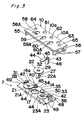
- Fig. 3 is a perspective view of an exploded state of an operation section of the electronic apparatus;
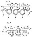
- Fig. 4 is a plan view of a base;
- Fig. 5 is a front view of the base, with being partially cut away;
- Fig. 6 is a side view of a lock key;
- Fig. 7A is a view looking in the direction X of Fig. 6;
- Fig. 7B is a view looking in the direction Y of Fig. 6;
- Fig. 8 is a view illustrating a locking (key protecting) operation by using the lock key;
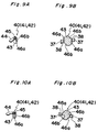
- Fig. 9A is a perspective view of a rotated state of a shutter at a covering canceling position;
- Fig. 9B is a diagram of positioning of the shutter at the covering canceling position;
- Fig. 10A is a perspective view of a rotated state of the shutter at a covering position;
- Fig. 10B is a diagram of positioning of the shutter at the covering position;
- Fig. 11A is a diagram of the operation section before locking (key protecting);
- Fig. 11B is a diagram of the operation section after locking (key protecting);
- Fig. 12 is a diagram of shutter moving distance regulating means;
- Fig. 13 is a perspective view of the shutter;
- Fig. 14 is a view illustrating the key protecting operation by using the lock key;
- Fig. 15 is a perspective view of an operation section of a conventional electronic apparatus; and
- Fig. 16 is a perspective view of another operation section of a conventional electronic apparatus.
-
- Hereinafter, embodiments of the invention will be described with reference to Figs. 1 to 14 of the accompanying drawings.
- An electronic apparatus A is generally configured by: a case 1; a
cover 2; an internal apparatus 4 which is accommodated in a housing 3 consisting of the case 1 and thecover 2; and afront cover 10. The housing 3 and thefront cover 10 constitute the main unit of the apparatus. As shown in Fig. 2, the internal apparatus 4 is generally configured by: first and second terminal blocks 5 and 6; aswitch unit 7; and acircuit board unit 9 in which many electronic parts are mounted on a printedcircuit board 8. - As shown in Fig. 2, the case 1 comprises the case body 1-1 of a substantially quadrangular shape, and a
unit mounting portion 11 is formed on the front face of the case body 1-1. A first terminalblock mounting portion 12 is formed on aside wall 1A of the case 1, and a second terminalblock mounting portion 13 is formed on a side wall 1B of the case 1. - The
switch unit 7 and thefront cover 10 are mounted on theunit mounting portion 11 of the case 1. The firstterminal block 5 is mounted on the first terminalblock mounting portion 12, and the secondterminal block 6 is mounted on the second terminalblock mounting portion 13. Thecircuit board unit 9 is mounted inside the case 1, and thecover 2 is mounted on the case 1, thereby constituting the electronic apparatus A. - On the front face of the electronic apparatus A, therefore, an operation section 400 (Fig. 1) consisting of the
switch unit 7 and thefront cover 10 is disposed. Terminal blocks 401 and 402 are disposed on both the sides across theoperation section 400, respectively. Arail engaging portion 403 is disposed on the rear face of the electronic apparatus A. - As shown in Figs. 2 and 3, the
switch unit 7 comprises atransparent base 14. As shown in Fig. 4, first, second, and thirdswitch holding holes face 14a of thebase 14. - As shown in Fig. 3, a
switch body 21A of aswitch 21 such as a time setting switch is rotatably inserted into and passed through the firstswitch holding hole 16. Aswitch body 22A of aswitch 22 such as a range setting switch is rotatably inserted into and passed through the secondswitch holding hole 17. Aswitch body 23A of aswitch 23 such as a mode changeover switch is rotatably inserted into and passed through the thirdswitch holding hole 18. - A
hook 27 is formed in the periphery of each of theswitch bodies switch bodies switch holding holes hooks 27 are slidingly in contact with the peripheries of the first, second, and thirdswitch holding holes - Flange-
like knobs switch bodies Cross grooves knobs - As shown in Fig. 4, first, second, and third
shutter holding cylinders face 14a of the base 14 so as to pass threrethrough. In each of the first, second, and thirdshutter holding cylinders like tongue pieces 37 are respectively formed at positions which are opposed to each other. Aprojection 38 is disposed on the inside of the tip end portion of each of thetongue pieces 37. - As shown in Fig. 3, a
first shutter 40 for covering the first switch is rotatably inserted into and passed through the firstshutter holding cylinder 34. Asecond shutter 41 for covering the second switch is rotatably inserted into and passed through the secondshutter holding cylinder 35. Athird shutter 42 for covering the third switch is rotatably inserted into and passed through the thirdshutter holding cylinder 36. - As shown in Figs. 9A and 9B, each of the first, second, and
third shutters portion 44 at the tip end of ashaft 43 so as to be perpendicular to theshaft 43. The tip end portion of each coveringportion 44 is made wider. A polygonal (heptagonal) engagingrecess 45 serving as a shutter operation portion is formed in the tip end face of theshaft 43. Two pairs ofgrooves shaft 43 are formed at positions of theshaft 43 which are opposed to each other, respectively. Each of the first, second, andthird shutters - The
first shutter 40 is disposed in the base 14 so that theshaft 43 of the shutter is inserted into and passed through the firstshutter holding cylinder 34. Thesecond shutter 41 is disposed in the base 14 so that theshaft 43 of the shutter is inserted into and passed through the secondshutter holding cylinder 35. Thethird shutter 42 is disposed in the base 14 so that theshaft 43 of the shutter is inserted into and passed through the thirdshutter holding cylinder 36. In each of the first, second, andthird shutters projections 38 of thetongue pieces 37 are disengeably engaged with thegrooves 46a of theshaft 43, respectively. - Light emitting diode
accommodating portions base 14, respectively. An engagingprojection 49 is disposed in each of the ends of thebase 14. - First, second, and third variable resistors (or dip switches and the like) which are not shown, and light emitting diodes (not shown) are mounted on the mounting face of the printed
circuit board 8 on which electronic parts are mounted. - The
front cover 10 has acover body 10A.Attachment legs cover body 10A. Engagingholes 57 are formed in theattachment legs face 10a of thecover body 10A, formed are a firstswitch operation hole 58, anarcuate display window 58A centered at the firstswitch operation hole 58, a secondswitch operation hole 59, and a thirdswitch operation hole 60. The second and third switch operation holes 59 and 60 haverectangular display windows display windows - First, second, and third shutter operation holes 61, 62, and 63 which are circular are formed in the
face 10a of thecover body 10A. Light emittingdiode display windows face 10a of thecover body 10A so as to be positioned in both the ends of the face. - The
base 14 is attached to the rear side of thefront cover 10 while engaging the engagingprojections 49 on both the ends with the engagingholes 57 of theattachment legs front cover 10. In this case, the first, second, andthird shutters cover body 10A thefront cover 10, whereby the shutters are prevented from slipping off. - In the
front cover 10, as shown in Fig. 11A, thecenter cross groove 31 of theknob 28 of thefirst switch 21 is positioned in the firstswitch operation hole 58. A numeral(s) (not shown) for displaying the time and indicated on theknob 28 is positioned in thedisplay window 58A. Thecenter cross groove 32 of theknob 29 of thesecond switch 22 is positioned in the secondswitch operation hole 59. A range setting symbol (not shown) indicated on theknob 29 is positioned in thedisplay window 59A. Thecenter cross groove 33 of the knob 30 of thethird switch 23 is positioned in the thirdswitch operation hole 60. A symbol (not shown) indicated on the knob 30 is positioned in thedisplay window 60A. - As shown in Fig. 11B, the
polygonal engaging portion 45 of thefirst shutter 40 is positioned in the firstshutter operation hole 61. The polygonal engagingportion 45 of thesecond shutter 41 is positioned in the secondshutter operation hole 62. The polygonal engagingportion 45 of thethird shutter 42 is positioned in the thirdshutter operation hole 63. The light emitting diodeaccommodating portions diode display windows - When the
switch unit 7 and thefront cover 10 are mounted on theunit mounting portion 11 of the case 1, the end portion of theswitch body 21A of thefirst switch 21 is coupled with a movable member of a first volume disposed on the mounting face of the printedcircuit board 8. Similarly, the end portion of theswitch body 22A of thesecond switch 22 is coupled with a movable member of a second volume, and the end portion of theswitch body 23A of thethird switch 23 is coupled with a movable member of a third volume. The light emitting diodes mounted on the mounting face of the printedcircuit board 8 are accommodated in the light emitting diodeaccommodating portions base 14, respectively. - Figs. 6 and 7 show a
lock key 70 serving as a special tool. Thelock key 70 has a pen-like shape. A toolswitch operation portion 71 having across engaging projection 71a is disposed in one end portion (upper end portion) of thelock key 70. A toolshutter operation portion 72 having an engagingprojection 72a of a polygonal prism-like shape (heptagonal prism-like shape) is disposed in the other end portion (lower end portion) of thelock key 70. Aclip 73 is attached to thelock key 70. Ahole 74 for attaching an anti-loss chain is disposed in the basal portion of theclip 73. - The electronic apparatus A which is configured as described above is attached to a rail member (not shown) by using the
rail engaging portion 403 on the rear face. - The worker can set the electronic apparatus A by using the
lock key 70 which is possessed by the worker. Specifically, the toolswitch operation portion 71 of thelock key 70 is inserted into the firstswitch operation hole 58 of thefront cover 10. Thecross engaging projection 71a of the toolswitch operation portion 71 is engaged with thecenter cross groove 31 of theknob 28 of thefirst switch 21. Thelock key 70 is then rotated, whereby thefirst switch 21 is rotated to change the preset time. In this case, the preset time is displayed by a numeral (s) in thedisplay window 58A. - Similarly, the tool
switch operation portion 71 of thelock key 70 is inserted into the secondswitch operation hole 59 of thefront cover 10. Thecross engaging projection 71a of the toolswitch operation portion 71 is engaged with thecenter cross groove 32 of theknob 29 of thesecond switch 22. Thelock key 70 is then rotated, whereby thesecond switch 22 is rotated to set the range. In this case, the set range is displayed by the range setting symbol in thedisplay window 59A. - Similarly, the tool
switch operation portion 71 of thelock key 70 is inserted into the thirdswitch operation hole 60 of thefront cover 10. Thecross engaging projection 71a of the toolswitch operation portion 71 is engaged with thecenter cross groove 33 of the knob 30 of thethird switch 23. Thelock key 70 is then rotated, whereby thethird switch 23 is rotated to set the output mode. In this case, the set output mode is displayed by a symbol in thedisplay window 60A. - When settings of the
first switch 21, thesecond switch 22, and thethird switch 23 are ended as described above, the toolshutter operation portion 72 of thelock key 70 is inserted into the firstshutter operation hole 61. The polygonalengaging projection 72a of the toolshutter operation portion 72 is engaged with the engagingrecess 45 of thefirst shutter 40. Thereafter, thelock key 70 is rotated in the right direction E in Fig. 8, whereby thefirst shutter 40 is rotated as shown in Figs. 9A to 10B. The coveringportion 44 is therefore moved immediately above thefirst switch 21 to close the firstswitch operation hole 58, whereby thefirst switch 21 is locked (key-protected) so as not to be externally operated (see Figs. 11A and 11B). - Similarly, the tool
shutter operation portion 72 of thelock key 70 is inserted into the secondshutter operation hole 62. The polygonalengaging projection 72a of the toolshutter operation portion 72 is engaged with the engagingrecess 45 of thesecond shutter 41. Thereafter, thelock key 70 is rotated in the right direction E in Fig. 8, whereby thesecond shutter 41 is rotated from the state of Fig. 9A to that of Fig. 10A. The coveringportion 44 is therefore moved immediately above thesecond switch 22 to close the secondswitch operation hole 59, whereby thesecond switch 22 is locked (key-protected) so as not to be externally operated (see Figs. 11A and 11B). - Similarly, the tool
shutter operation portion 72 of thelock key 70 is inserted into the thirdshutter operation hole 63. The polygonalengaging projection 72a of the toolshutter operation portion 72 is engaged with the engagingrecess 45 of thethird shutter 42. Thereafter, thelock key 70 is rotated in the right direction E in Fig. 8, whereby thethird shutter 42 is rotated from the state of Fig. 9A to that of Fig. 10A. The coveringportion 44 is therefore moved immediately above the engagingrecess 45 of thethird switch 23 to close the thirdswitch operation hole 60, whereby thethird switch 23 is locked (key-protected) so as not to be externally operated (see Figs. 11A and 11B). - In a lock canceling position by the first, second, or
third shutter projections 38 of thetongue pieces 37 are disengeably engaged with the pair of opposinggrooves 46a of theshaft 43 of the first, second, orthird shutter third shutter projections 38 of thetongue pieces 37 are disengaged from the opposinggrooves 46a of theshaft 43, and then engaged with the other pair ofgrooves 46b. Therefore, the locking by the first, second, orthird shutter grooves shafts 43 of the first, second, andthird shutters projections 38 of thetongue pieces 37 constitute positioning means. - As shown in Fig. 12, a
first recess 66 which has a fan-like shape and is centered at the firstshutter operation hole 61, asecond recess 67 which has a fan-like shape and is centered at the secondshutter operation hole 62, and athird recess 68 which has a fan-like shape and is centered at the thirdshutter operation hole 63 may be formed in the rear side of theface 10a of thecover body 10A. - In this case, the covering
portion 44 of thefirst shutter 40 is housed in thefirst recess 66 so as to be swingable within a predetermined angular range, the coveringportion 44 of thesecond shutter 41 is housed in thesecond recess 67 so as to be swingable within a predetermined angular range, and the coveringportion 44 of thethird shutter 42 is housed in thethird recess 68 so as to be swingable within a predetermined angular range. When the first, second, orthird shutter portion 44 collides against the wall of the first, second, orthird recess third recesses - In the embodiment described above, when setting of the first switch 21 (the second or
third switch 22 or 23) is ended, the toolshutter operation portion 72 of thelock key 70 is inserted into the first shutter operation hole 61 (the second or thirdshutter operation hole 62 or 63). Theshutter operation portion 72 is then engaged with the engagingrecess 45 of the first shutter 40 (the second orthird shutter 41 or 42). Thereafter, thelock key 70 is rotated, so that the first shutter 40 (the second orthird shutter 41 or 42) is rotated. The coveringportion 44 is therefore moved immediately above the first switch 21 (the second orthird switch 22 or 23) to close the first switch operation hole 58 (the second or thirdswitch operation hole 59 or 60), whereby the first switch 21 (the second orthird switch 22 or 23) can be locked (key-protected) so as not to be externally operated. - Alternatively, the covering operation by a shutter may be performed only on one of the first, second, and
third switches first switch 21 maybe subjected to the covering operation byfirst shutter 40, and the covering operation by a shutter may not be performed on the second andthird switches third switches - Each of the engaging
recesses 45 serving as shutter operation portions is formed as a heptagonal recess, and theshutter operation portion 72 of thelock key 70 is formed as the engagingprojection 72a of a heptagonal prism-like shape. The shapes are not restricted to them. When theshutter operation portion 72 of thelock key 70 has a shape of a cross projection, a triangular prism, a rectangular prism, a pentagonal prism, or the like, for example, the engagingrecesses 45 has a shape of a cross groove, a triangular, rectangular, or pentagonal recess, or the like. The engaging recesses 45 serving as shutter operation portions may have any shape as far as the shape is in conformity with theshutter operation portion 72 of thelock key 70. - Alternatively, the engaging
recesses 45 serving as shutter operation portions may be formed as engaging projections 45' of a polygonal prism-like shape, and theshutter operation portion 72 of thelock key 70 may be formed as a polygonalengaging recess 72a' so as to be engageable with the engaging projections 45'. Figs. 13 and 14 show this example. - In the embodiment described above, the first, second, and
third shutters third shutters
Claims (7)
- A key protection structure for an electronic apparatus in which a switch operation hole corresponding to a switch operation portion of each of switches that are incorporated in a main unit of said apparatus is disposed in said apparatus main unit, and said switch is activated by operating said switch operation portion through said switch operation hole, whereinsaid switch operation portion is covered by covering means in which covering is cancelled only by a special tool.
- A key protection structure for an electronic apparatus according to claim 1, wherein the covering of said switch operation portion by said covering means is performed on one or more of said switches which is required to be covered.
- A key protection structure for an electronic apparatus in which a switch operation hole corresponding to a switch operation portion of each of switches that are incorporated in a main unit of said apparatus is disposed in said apparatus main unit, and said switch is activated by operating said switch operation portion through said switch operation hole, whereinsaid structure comprises:a shutter which covers said switch operation hole and cancels the covering;a shutter operation portion which is disposed in said shutter and with which a tool shutter operation portion of a special tool is to be engaged; anda shutter operation hole which is disposed in said apparatus main unit, which corresponds to said shutter operation portion of said shutter, and into which said special tool is to be inserted.
- A key protection structure for an electronic apparatus according to claim 3, wherein said structure comprises positioning means for positioning said shutter at either of a covering position where said shutter covers said switch operation hole, and a covering canceling position where said shutter does not cover from said switch operation hole.
- A key protection structure for an electronic apparatus according to claim 3, wherein said structure comprises moving distance limiting means for limiting a moving distance of said shutter.
- A key protection structure for an electronic apparatus according to claim 3, wherein said shutter operation portion is an engaging portion which has a special shape, and with which said tool shutter operation portion of said special tool is to be engaged.
- A key protection structure for an electronic apparatus in which an operation section consisting of a switch unit and a front cover is disposed in a main unit of said apparatus, plural switches are disposed by using said switch unit as a base, a switch operation hole corresponding to a switch operation portion of each of said switches is disposed in said front cover, and said switch is activated by operating said switch operation portion through said switch operation hole, whereinsaid shutter is configured by forming a covering portion at a tip end of a shaft, said covering portion being perpendicular to said shaft, and forming an engaging portion with which a tool shutter operation portion of a special tool is to be engaged, in a tip end face of said shaft,plural shutter holding cylinders are disposed in a face of said base,a shutter operation hole which corresponds to said engaging portion of each shutter, and into which said special tool is to be inserted is disposed in said front cover,said shutter is disposed on said base while said shaft is inserted into and passed through corresponding one of said shutter holding cylinders, and said engaging portion of said shutter is positioned in said shutter operation hole by superposing said front cover on said switch unit.
Applications Claiming Priority (2)
| Application Number | Priority Date | Filing Date | Title |
|---|---|---|---|
| JP23553999A JP3948168B2 (en) | 1999-08-23 | 1999-08-23 | Key protection structure of electronic equipment |
| JP23553999 | 1999-08-23 |
Publications (2)
| Publication Number | Publication Date |
|---|---|
| EP1081731A1 true EP1081731A1 (en) | 2001-03-07 |
| EP1081731B1 EP1081731B1 (en) | 2002-11-06 |
Family
ID=16987489
Family Applications (1)
| Application Number | Title | Priority Date | Filing Date |
|---|---|---|---|
| EP00117808A Expired - Lifetime EP1081731B1 (en) | 1999-08-23 | 2000-08-18 | Key protection structure for an electronic apparatus |
Country Status (7)
| Country | Link |
|---|---|
| US (1) | US6373686B1 (en) |
| EP (1) | EP1081731B1 (en) |
| JP (1) | JP3948168B2 (en) |
| KR (1) | KR100415301B1 (en) |
| AT (1) | ATE227469T1 (en) |
| DE (1) | DE60000714T2 (en) |
| TW (1) | TW447230B (en) |
Families Citing this family (2)
| Publication number | Priority date | Publication date | Assignee | Title |
|---|---|---|---|---|
| DE102008008716A1 (en) * | 2008-02-11 | 2009-08-13 | Weidmüller Interface GmbH & Co. KG | Electronics housing with a printed circuit board and method for producing an electronics housing |
| US20110147170A1 (en) * | 2009-12-18 | 2011-06-23 | Li-Fen Liao | Secure locking mechanism for pushbutton control box |
Citations (1)
| Publication number | Priority date | Publication date | Assignee | Title |
|---|---|---|---|---|
| FR2631160A1 (en) * | 1988-05-05 | 1989-11-10 | Mang Ets Gerard | Control apparatuses, one or more functions of which can be put into service or not, or else be modified |
Family Cites Families (5)
| Publication number | Priority date | Publication date | Assignee | Title |
|---|---|---|---|---|
| GR82158B (en) * | 1983-06-17 | 1984-12-13 | Knudsen Nordisk Elect | |
| US4527310A (en) * | 1983-07-22 | 1985-07-09 | I. D. Engineering, Inc. | Secure release apparatus for anti-theft fastening device |
| DE4034609A1 (en) * | 1989-11-02 | 1992-05-07 | Zimmermann Silvia | Multifunction key switch for stimulation current unit for medical bathing - ensures that after switch on and acceleration of intensity no acceleration of switch position is possible at board using shielding cover |
| ES2101378T3 (en) * | 1993-04-21 | 1997-07-01 | Sace Spa | SEPARABLE SWITCH. |
| KR100208936B1 (en) * | 1996-12-30 | 1999-07-15 | 윤종용 | Message transmission method using dedicated key in two-way wireless pager |
-
1999
- 1999-08-23 JP JP23553999A patent/JP3948168B2/en not_active Expired - Lifetime
-
2000
- 2000-08-16 US US09/639,994 patent/US6373686B1/en not_active Expired - Lifetime
- 2000-08-17 KR KR10-2000-0047478A patent/KR100415301B1/en not_active Expired - Fee Related
- 2000-08-18 TW TW089116736A patent/TW447230B/en not_active IP Right Cessation
- 2000-08-18 EP EP00117808A patent/EP1081731B1/en not_active Expired - Lifetime
- 2000-08-18 DE DE60000714T patent/DE60000714T2/en not_active Expired - Lifetime
- 2000-08-18 AT AT00117808T patent/ATE227469T1/en not_active IP Right Cessation
Patent Citations (1)
| Publication number | Priority date | Publication date | Assignee | Title |
|---|---|---|---|---|
| FR2631160A1 (en) * | 1988-05-05 | 1989-11-10 | Mang Ets Gerard | Control apparatuses, one or more functions of which can be put into service or not, or else be modified |
Also Published As
| Publication number | Publication date |
|---|---|
| DE60000714T2 (en) | 2003-07-24 |
| DE60000714D1 (en) | 2002-12-12 |
| JP3948168B2 (en) | 2007-07-25 |
| KR20010050101A (en) | 2001-06-15 |
| KR100415301B1 (en) | 2004-01-16 |
| ATE227469T1 (en) | 2002-11-15 |
| US6373686B1 (en) | 2002-04-16 |
| TW447230B (en) | 2001-07-21 |
| EP1081731B1 (en) | 2002-11-06 |
| JP2001059368A (en) | 2001-03-06 |
Similar Documents
| Publication | Publication Date | Title |
|---|---|---|
| AU658584B2 (en) | Vehicle anti-theft system | |
| US4705959A (en) | Switch control device for motor vehicle | |
| EP1602873B1 (en) | Portable signal light, motor vehicle guiding tool, and motor vehicle guiding method | |
| EP1056913B1 (en) | Door terminal with an emergency door opening button and a display module | |
| CA2142590A1 (en) | Powered reversing ratchet driver | |
| EP1081731B1 (en) | Key protection structure for an electronic apparatus | |
| US20040179149A1 (en) | Protective mask with a liquid crystal display panel | |
| JP4741952B2 (en) | Operation switch | |
| US20150085391A1 (en) | Bottom mount buttons for a rearview assembly | |
| US5239143A (en) | Rocker switch operator means | |
| DE69713364D1 (en) | CONTROL PANEL | |
| CN119795111A (en) | Power tool and removable user interface guards | |
| JP6214920B2 (en) | Motor drive device | |
| JPH11315731A (en) | Work machine throttle lever | |
| US4390074A (en) | Operating key for electrical scales | |
| JP2523759Y2 (en) | Switch unit with display | |
| KR950004945Y1 (en) | Dial holder for a small timer | |
| JP4801562B2 (en) | Rotary switch device | |
| JP3007824U (en) | Target plate with blinking illumination | |
| JPH0581473U (en) | Door lock monitor device | |
| JP2523330Y2 (en) | Handy controller | |
| JPS5853630Y2 (en) | Operation mode setting device for control equipment | |
| JPH0330985Y2 (en) | ||
| JP2000259108A (en) | Check item confirmation display | |
| JPH0727601Y2 (en) | Rotation operation type electronic parts operation mechanism |
Legal Events
| Date | Code | Title | Description |
|---|---|---|---|
| PUAI | Public reference made under article 153(3) epc to a published international application that has entered the european phase |
Free format text: ORIGINAL CODE: 0009012 |
|
| 17P | Request for examination filed |
Effective date: 20000914 |
|
| AK | Designated contracting states |
Kind code of ref document: A1 Designated state(s): AT BE CH CY DE DK ES FI FR GB GR IE IT LI LU MC NL PT SE |
|
| AX | Request for extension of the european patent |
Free format text: AL;LT;LV;MK;RO;SI |
|
| AKX | Designation fees paid |
Free format text: AT BE CH CY DE DK ES FI FR GB GR IE IT LI LU MC NL PT SE |
|
| GRAG | Despatch of communication of intention to grant |
Free format text: ORIGINAL CODE: EPIDOS AGRA |
|
| RIN1 | Information on inventor provided before grant (corrected) |
Inventor name: OGAWA, TADAHIKO, OMRON CORP., 801 MINAMIFUDOUDOU Inventor name: TAKAKUWA, HAJIME, OMRON CORP., 801 MINAMIFUDOUDOU Inventor name: TOMIOKA,KIYOTAKA, OMRON CORP., 801 MINAMIFUDOUDOU Inventor name: YAMAMOTO,HIROYUKI, OMRON CORP., 801 MINAMIFUDOUDO |
|
| 17Q | First examination report despatched |
Effective date: 20020108 |
|
| GRAG | Despatch of communication of intention to grant |
Free format text: ORIGINAL CODE: EPIDOS AGRA |
|
| GRAH | Despatch of communication of intention to grant a patent |
Free format text: ORIGINAL CODE: EPIDOS IGRA |
|
| GRAH | Despatch of communication of intention to grant a patent |
Free format text: ORIGINAL CODE: EPIDOS IGRA |
|
| GRAA | (expected) grant |
Free format text: ORIGINAL CODE: 0009210 |
|
| AK | Designated contracting states |
Kind code of ref document: B1 Designated state(s): AT BE CH CY DE DK ES FI FR GB GR IE IT LI LU MC NL PT SE |
|
| PG25 | Lapsed in a contracting state [announced via postgrant information from national office to epo] |
Ref country code: NL Free format text: LAPSE BECAUSE OF FAILURE TO SUBMIT A TRANSLATION OF THE DESCRIPTION OR TO PAY THE FEE WITHIN THE PRESCRIBED TIME-LIMIT Effective date: 20021106 Ref country code: FI Free format text: LAPSE BECAUSE OF FAILURE TO SUBMIT A TRANSLATION OF THE DESCRIPTION OR TO PAY THE FEE WITHIN THE PRESCRIBED TIME-LIMIT Effective date: 20021106 Ref country code: GR Free format text: LAPSE BECAUSE OF FAILURE TO SUBMIT A TRANSLATION OF THE DESCRIPTION OR TO PAY THE FEE WITHIN THE PRESCRIBED TIME-LIMIT Effective date: 20021106 Ref country code: LI Free format text: LAPSE BECAUSE OF FAILURE TO SUBMIT A TRANSLATION OF THE DESCRIPTION OR TO PAY THE FEE WITHIN THE PRESCRIBED TIME-LIMIT Effective date: 20021106 Ref country code: BE Free format text: LAPSE BECAUSE OF FAILURE TO SUBMIT A TRANSLATION OF THE DESCRIPTION OR TO PAY THE FEE WITHIN THE PRESCRIBED TIME-LIMIT Effective date: 20021106 Ref country code: AT Free format text: LAPSE BECAUSE OF FAILURE TO SUBMIT A TRANSLATION OF THE DESCRIPTION OR TO PAY THE FEE WITHIN THE PRESCRIBED TIME-LIMIT Effective date: 20021106 Ref country code: CH Free format text: LAPSE BECAUSE OF FAILURE TO SUBMIT A TRANSLATION OF THE DESCRIPTION OR TO PAY THE FEE WITHIN THE PRESCRIBED TIME-LIMIT Effective date: 20021106 |
|
| REF | Corresponds to: |
Ref document number: 227469 Country of ref document: AT Date of ref document: 20021115 Kind code of ref document: T |
|
| REG | Reference to a national code |
Ref country code: GB Ref legal event code: FG4D |
|
| REG | Reference to a national code |
Ref country code: CH Ref legal event code: EP |
|
| REG | Reference to a national code |
Ref country code: IE Ref legal event code: FG4D |
|
| RAP2 | Party data changed (patent owner data changed or rights of a patent transferred) |
Owner name: OMRON CORPORATION |
|
| REF | Corresponds to: |
Ref document number: 60000714 Country of ref document: DE Date of ref document: 20021212 |
|
| RIN2 | Information on inventor provided after grant (corrected) |
Free format text: OGAWA, TADAHIKO, OMRON CORP., 801 MINAMIFUDODO-CHO * TAKAKUWA, HAJIME, OMRON CORP. 801 MINAMIFUDODO-CHO * YAMAMOTO,HIROYUKI, OMRON CORP. 801 MINAMIFUDODOCHO * TOMIOKA,KIYOTAKA, OMRON CORP. 801 MINAMIFUDODO-CHO |
|
| NLT2 | Nl: modifications (of names), taken from the european patent patent bulletin |
Owner name: OMRON CORPORATION |
|
| PG25 | Lapsed in a contracting state [announced via postgrant information from national office to epo] |
Ref country code: PT Free format text: LAPSE BECAUSE OF FAILURE TO SUBMIT A TRANSLATION OF THE DESCRIPTION OR TO PAY THE FEE WITHIN THE PRESCRIBED TIME-LIMIT Effective date: 20030206 Ref country code: SE Free format text: LAPSE BECAUSE OF FAILURE TO SUBMIT A TRANSLATION OF THE DESCRIPTION OR TO PAY THE FEE WITHIN THE PRESCRIBED TIME-LIMIT Effective date: 20030206 Ref country code: DK Free format text: LAPSE BECAUSE OF FAILURE TO SUBMIT A TRANSLATION OF THE DESCRIPTION OR TO PAY THE FEE WITHIN THE PRESCRIBED TIME-LIMIT Effective date: 20030206 |
|
| NLV1 | Nl: lapsed or annulled due to failure to fulfill the requirements of art. 29p and 29m of the patents act | ||
| ET | Fr: translation filed | ||
| REG | Reference to a national code |
Ref country code: CH Ref legal event code: PL |
|
| PG25 | Lapsed in a contracting state [announced via postgrant information from national office to epo] |
Ref country code: ES Free format text: LAPSE BECAUSE OF FAILURE TO SUBMIT A TRANSLATION OF THE DESCRIPTION OR TO PAY THE FEE WITHIN THE PRESCRIBED TIME-LIMIT Effective date: 20030529 |
|
| PG25 | Lapsed in a contracting state [announced via postgrant information from national office to epo] |
Ref country code: IE Free format text: LAPSE BECAUSE OF NON-PAYMENT OF DUE FEES Effective date: 20030818 Ref country code: CY Free format text: LAPSE BECAUSE OF FAILURE TO SUBMIT A TRANSLATION OF THE DESCRIPTION OR TO PAY THE FEE WITHIN THE PRESCRIBED TIME-LIMIT Effective date: 20030818 Ref country code: LU Free format text: LAPSE BECAUSE OF NON-PAYMENT OF DUE FEES Effective date: 20030818 |
|
| PG25 | Lapsed in a contracting state [announced via postgrant information from national office to epo] |
Ref country code: MC Free format text: LAPSE BECAUSE OF NON-PAYMENT OF DUE FEES Effective date: 20030831 |
|
| PLBE | No opposition filed within time limit |
Free format text: ORIGINAL CODE: 0009261 |
|
| STAA | Information on the status of an ep patent application or granted ep patent |
Free format text: STATUS: NO OPPOSITION FILED WITHIN TIME LIMIT |
|
| 26N | No opposition filed |
Effective date: 20030807 |
|
| REG | Reference to a national code |
Ref country code: IE Ref legal event code: MM4A |
|
| PG25 | Lapsed in a contracting state [announced via postgrant information from national office to epo] |
Ref country code: IT Free format text: LAPSE BECAUSE OF NON-PAYMENT OF DUE FEES;WARNING: LAPSES OF ITALIAN PATENTS WITH EFFECTIVE DATE BEFORE 2007 MAY HAVE OCCURRED AT ANY TIME BEFORE 2007. THE CORRECT EFFECTIVE DATE MAY BE DIFFERENT FROM THE ONE RECORDED. Effective date: 20050818 |
|
| PGRI | Patent reinstated in contracting state [announced from national office to epo] |
Ref country code: IT Effective date: 20091201 |
|
| REG | Reference to a national code |
Ref country code: DE Ref legal event code: R082 Ref document number: 60000714 Country of ref document: DE Representative=s name: KILIAN KILIAN & PARTNER, DE Ref country code: DE Ref legal event code: R082 Ref document number: 60000714 Country of ref document: DE Representative=s name: KILIAN KILIAN & PARTNER MBB PATENTANWAELTE, DE |
|
| REG | Reference to a national code |
Ref country code: FR Ref legal event code: PLFP Year of fee payment: 17 |
|
| REG | Reference to a national code |
Ref country code: FR Ref legal event code: PLFP Year of fee payment: 18 |
|
| REG | Reference to a national code |
Ref country code: FR Ref legal event code: PLFP Year of fee payment: 19 |
|
| PGFP | Annual fee paid to national office [announced via postgrant information from national office to epo] |
Ref country code: IT Payment date: 20190821 Year of fee payment: 20 Ref country code: DE Payment date: 20190806 Year of fee payment: 20 Ref country code: FR Payment date: 20190711 Year of fee payment: 20 |
|
| PGFP | Annual fee paid to national office [announced via postgrant information from national office to epo] |
Ref country code: GB Payment date: 20190816 Year of fee payment: 20 |
|
| REG | Reference to a national code |
Ref country code: DE Ref legal event code: R071 Ref document number: 60000714 Country of ref document: DE |
|
| REG | Reference to a national code |
Ref country code: GB Ref legal event code: PE20 Expiry date: 20200817 |
|
| PG25 | Lapsed in a contracting state [announced via postgrant information from national office to epo] |
Ref country code: GB Free format text: LAPSE BECAUSE OF EXPIRATION OF PROTECTION Effective date: 20200817 |